 ,1,2,3,∗, Mansoor Khan1, Shabir Ahmad1, Muhammad Tayyab1, Haseena Bibi2, Hazrat Ali41 Department of Physics, Govt Post Graduate College Dargai Malakand,
 2 Department of Physics,
3 Department of Physics,
4 Department of Physics,
First author contact:
Received:2020-05-16Revised:2020-09-3Accepted:2020-09-9Online:2020-10-27

Abstract
Keywords:
PDF (449KB)MetadataMetricsRelated articlesExportEndNote|Ris|BibtexFavorite
Cite this article
Habibur Rahman, Mansoor Khan, Shabir Ahmad, Muhammad Tayyab, Haseena Bibi, Hazrat Ali. Polarization state and image rotation via spontaneously generated coherence in a spinning fast light medium. Communications in Theoretical Physics[J], 2020, 72(11): 115502- doi:10.1088/1572-9494/abb7dc
1. Introduction
The propagation of light pulse in a spinning window encounters a pull known as ether drag. The phenomenon of ether drag was first discussed by Fresnel [1]. Jones et al made the experimental confirmation [2 –4]. When a pulse of light gets in a rotating window it becomes pulled in a transverse or linear direction depending upon the situation [5]. Fizeau et al verified the longitudinal dragging of light [6]. The state of electric field vector orientation is called polarization. The process of confinement of light pulse into a single plane is also called polarization. In the presence of polarization state rotation, the transmitting image also rotates. This is because of orbital and spin gyration. It is well known that optical spin and orbital angular momenta both cause rotation of polarization state and images [7, 8]. Optical polarization state rotation occurs due to movement of light through the spinning axes in a rotating window [9]. Light propagating through a spinning medium results in the polarization state rotation and its images. Second harmonic generation and enhancement in photon dragging in a doped graphene was discussed in detail [10]. Photon drag and surface plasmon polariton under Kerr Effect were theoretically investigated [11]. The enhanced dragging effect through a spinning window with electromagnetically induced transparency (EIT) condition for a slow light were studied by Iqbal et al [12]. In recent years enhanced optical rotation has been an active field of research because of its fundamental and practical interest. Superluminal propagation of light in a system occurs due to anomalous dispersion. The time coordinate is negative for a fast light propagation. Enhanced dragging effect has useful applications in the detection of slow/fast motion, position control, image coding and cloaking technology [13]. Light pulse dragging can also be used in four wave mixing [14] and matching the phase condition for Brillouin scattering [15].Quantum interference and quantum coherence has been an active field for researchers in the last two decades. Quantum interference and coherence in an atomic medium results in different phenomena, like coherent population trapping (CPT) [16], slow/fast light, lasing without inversion (LWI) and electromagnetically induced transparency (EIT) [17 –19]. The optical and spectral profiles of quantum systems can be described using quantum interference. It has been found that LWI can be realized without a decaying beam [20]. Quantum interference has potential application in linear/non-linear optics [21]. The spontaneously generated coherence (SGC) achieved in the decaying laser beams from the upper two excited states into a single ground state is a useful quantum interference. SGC mainly depends on the degeneracy of quantum state and non-orthogonality of the dipole moment. The effect of SGC has been investigated for several different purposes, such as switching on a micro wave field utilizing the anisotropy of vacuum etc [22]. A number of attempts have been successful in manipulating SGC experimentally [23]. SGC can be physically realized in Rb87 atoms using the optical trap technique.
In this paper we have explored the effect of SGC to manipulate polarization state rotations and their transmitted images. We show that a fast light rotating medium rotates the polarization states and their images in opposite directions. The results for optical rotation under SGC in fast light medium are several times more enhanced than the results obtained under Kerr Effect [24].
2. Model and equations
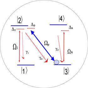
The proposed model is a four-level atomic system containing two ground states and two excited degenerate states. The stateFigure 1.
 New window|Download| PPT slide
Figure 1.Schematic of the proposed four-level N-type Rb87 atom.
To derive
The group index can be expressed as:
3. Results and discussion
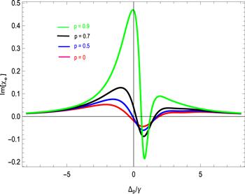
There is no effect on the polarization state rotation and images when the spinning velocity of medium is zero. A spinning medium having spinning velocity (In figure 2 the plot is traced for the absorption of light pulse propagating in a spinning medium. When the SGC factor p is zero the absorption is very small, as shown by the pink solid line. When the SGC factor is increased from p =0 to p =0.5, 0.7 and to 0.9 the absorption increases as shown by the blue, black and green solid lines. Moreover, the absorption peak reaches the saturated region near the resonance point both in the positive as well as in the negative domain. The absorption is positive for negative probe field detuning, while it is negative when the probe detuning is nearly 1γ . When the detuning further increased the absorption again became positively saturated. From figure 2 it is clear that the absorption spectrum enhances with the effect of SGC. However the absorption spectrum vanishes for large probe field detuning on both sides.
Figure 2.
 New window|Download| PPT slide
Figure 2.Absorption spectral profile of spinning medium with the presence and absence of SGC effect versus Δp /γ such that γ =1 MHz, γ1 =γ2 =γ3 =1γ, Δc =Δk =0γ,
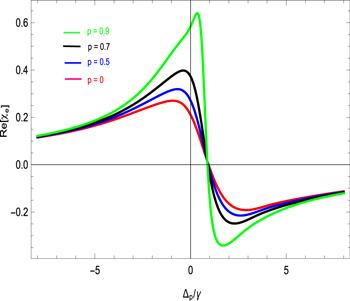
In figure 3 the plot is traced for the dispersion spectrum versus probe field detuning, while other spectroscopic parameters remain the same as in figure 2 . The corresponding group index is negative and enhances in the negative domain. When the SGC factor is zero the dispersion is minimum. The slope of the dispersion spectrum is anomalous near the resonance point as shown by the pink solid line. When we increased the SGC factor from zero to 0.5, 0.7 and then to 0.9 dispersion slope became steeper, revealing an enhancement in superluminal propagation of light due to the SGC effect. The suggested atomic model demonstrates the enhancement in fast light propagation under SGC.
Figure 3.
 New window|Download| PPT slide
Figure 3.Dispersion spectrum of spinning medium with the presence and absence of SGC effect versus Δp /γ such that γ =1 MHz, γ1 =γ2 =γ3 =1γ, Δc =Δk =0γ,
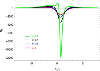
In figure 4 the plot is traced for the group index versus probe field detuning. When ωs =0 rps then there is no rotation; when ωs stays on 1000 rps then considerable rotation in polarization state rotation and images were noted. When the SGC factor is zero the group index is minimum, indicating a very small change in the propagating light pulse in this suggested model. When we increase the SGC factor, group index enhances in the negative domain. When the SGC factor is increased from zero to 0.5, 0.7 and then to 0.9, the corresponding group index is negative and enhances in the negative domain as shown by the solid pink, blue, black and green line in figure 4 .
Figure 4.
 New window|Download| PPT slide
Figure 4.Group refractive index in spinning medium with the presence and absence of SGC effect versus Δp /γ such that γ =1 MHz, γ1 =γ2 =γ3 =1γ, Δc =Δk =0γ,
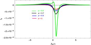
Figure 5 shows the time advancement versus probe field detuning in the proposed atomic medium. The group velocity, group index and time are related as
Figure 5.
 New window|Download| PPT slide
Figure 5.Time advancement in the spinning medium with the presence and absence of SGC effect versus Δp /γ such that γ =1 MHz, γ1 =γ2 =γ3 =1γ, Δc =Δk =0γ,
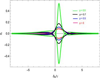
Figure 6 shows the degree of polarization state rotation and images versus probe detuning. We observe 0.5 radian angle of rotation in this suggested atomic model. When the spinning medium is rotating clockwise the polarization state and images will rotate counterclockwise [24]. However, for slow light the rotation will occur in the same direction. The SGC effect significantly enhances the degree of rotation. We report 2.5 times enhancement in the rotational angle measured under SGC.
Figure 6.
 New window|Download| PPT slide
Figure 6.Rotations of polarization state of light and their transmitted image in the spinning medium with the presence and absence of SGC effect versus Δp /γ such that γ =1 MHz, γ1 =γ2 =γ3 =1γ, Δc =Δk =0γ, Φ1 =Φ2 =1 Ωg =4.5γ, Ωc =0.6γ and d=6 mm.
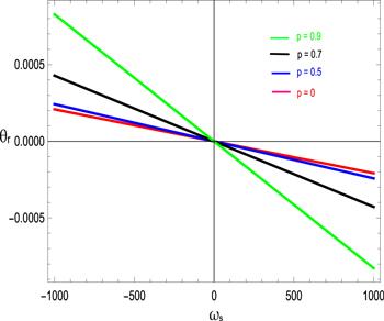
In figure 7 we demonstrate that the polarization states and their transmitted images rotate counterclockwise for a clockwise spinning medium. The SGC factor affecting the rotation of polarization state and images are as shown in figure 7 . The proposed medium is a spinning fast light medium. Figure 7 fulfills the basic theme of a spinning fast light medium. The rotation is zero when ωs stays on zero. When
Figure 7.
 New window|Download| PPT slide
Figure 7.Rotations of polarization states of light and their transmitted images in the spinning medium with the presence and absence of SGC effect versus ωs such that γ =1 MHz, γ1 =γ2 =γ3 =1γ, Δc =Δk =0γ, Φ1 =Φ2 =1, Ωg =4.5γ, Ωc =1.5γ and d =6 mm.
4. Conclusion
In summary the propagations of fast light pulses in a four-level atomic configuration were studied. The proposed atomic model can be realized in rubidium Rb87 atom. We investigate SGC effect on rotary photon. In the fast light spinning medium the rotation of medium and polarization state rotates in the opposite direction. In this suggested model the calculated group index is −12000. The observed rotational angle of polarization states and images due to SGC effect is 0.5 radian. The measured value of the rotational angle under the effect of SGC is several times more enhanced than the results obtained under Kerr Effect. The time for the propagating fast light pulse is negative. We show that the time advances from 0.5 to 2.5 microsecond in our proposed system. These results may find applications in telecommunication systems, image coding and cloaking technology.Reference By original order
By published year
By cited within times
By Impact factor
[Cited within: 1]
DOI:10.1098/rspa.1972.008 [Cited within: 1]
DOI:10.1098/rspa.1975.0141
DOI:10.1098/rspa.1976.0082 [Cited within: 1]
DOI:10.1126/science.1203984 [Cited within: 1]
[Cited within: 1]
DOI:10.1103/PhysRevA.45.8185 [Cited within: 1]
DOI:10.1103/PhysRevLett.100.153902 [Cited within: 1]
DOI:10.1126/science.1096914 [Cited within: 1]
DOI:10.1364/OL.38.000748 [Cited within: 1]
DOI:10.1103/PhysRevA.96.013848 [Cited within: 1]
DOI:10.1016/j.physleta.2017.07.037 [Cited within: 1]
DOI:10.1103/PhysRevA.86.013806 [Cited within: 1]
DOI:10.1103/PhysRevLett.97.113001 [Cited within: 1]
DOI:10.1103/PhysRevLett.86.2006 [Cited within: 1]
DOI:10.1088/0022-3700/15/1/012 [Cited within: 1]
DOI:10.1364/OL.19.002018 [Cited within: 1]
DOI:10.1063/1.881806
DOI:10.1007/BF01426089 [Cited within: 1]
DOI:10.1103/PhysRevA.69.043814 [Cited within: 1]
DOI:10.1364/JOSAB.26.001862 [Cited within: 1]
DOI:10.1103/PhysRevLett.84.5500 [Cited within: 1]
DOI:10.1103/PhysRevA.79.043810 [Cited within: 1]
DOI:10.1088/1054-660X/24/11/115404 [Cited within: 4]
DOI:10.1103/PhysRevLett.64.1107
DOI:10.1103/PhysRevA.70.023802 [Cited within: 1]
