全文HTML
--> --> -->虽然目前多种数值方法被成功应用于辐射导热耦合问题的求解, 然而非规则形状介质内辐射导热耦合传热的高精度数值求解仍旧面临较大的挑战[30]. 对于含有弯曲壁面的非规则形状介质而言, 辐射强度在界面附近等局部区域的变化率较大, 而传统连续型数值方法则是基于全局形函数对未知量进行加权近似, 没有考虑局部区域的大梯度辐射强度分布, 计算结果往往存在较大误差. 如文献[31]中即使采用较为细密的网格划分, 采用有限体积法所得辐射热流和温度分布曲线仍旧存在非常明显的振荡, 因此, 扩展高精度数值算法求解辐射导热耦合传热方程, 获得非规则形状介质内辐射导热耦合问题的高精度数值解具有重要意义.
间断有限元法(discontinuous finite element method, DFEM)[32]是在传统连续型有限元法(finite element method, FEM)基础上发展起来的一种高精度数值方法. 利用传统FEM的空间网格划分, DFEM利用相邻单元边界的数值通量从而释放了FEM强加的内部单元连续性. 由于DFEM形函数构造和控制方程求解均在每个离散单元上进行, 因此该方法兼具较好的几何灵活性和局部守恒性, 并被逐渐应用于辐射传输问题的求解[33-38]. 本文采用DFEM求解辐射传输方程和能量扩散方程, 将其扩展应用于辐射导热耦合传热问题的求解, 验证了数值结果的精确性并给出了典型非规则形状介质内辐射导热耦合传热问题的高精度数值解.
首先分析辐射传输方程. 参与性介质内辐射传输方程的离散坐标形式可写为


在DFEM应用过程中, 计算区域首先被划分为紧密相邻的离散单元, 如图1(a)所示. 待求解的目标量(如辐射强度)在相邻单元边界上被认为是非连续的, 每个单元上的数值解是相互独立的, 如图1(b)所示. DFEM在每个离散单元上求解控制方程, 相邻单元之间通过数值通量相互连接, 从而保证了计算区域的连续性.
 图 1 (a)空间网格; (b)相邻单元间数值通量示意图
Figure1. (a) Spatial mesh; (b) sketch of numerical flux across the adjacent elements.
以图1(b)中的单元e作为研究对象进行分析, 在该单元上对(1)式使用权函数


然后分析能量扩散方程. 能量扩散方程表示为

首先进行网格无关性检验. 分别将方形区域的边界均匀划分为5, 10和15个单元, 二维计算区域离散为Ne = 62, 226和504个三角形单元. 图2(a)所示为角度划分为Nθ × Nφ = 10 × 20, 不同离散单元条件下介质对称线x/L = 0.5上的无量纲温度T/Tb的分布规律. 图2(b)所示为离散单元数Ne = 226, 不同角度划分Nθ × Nφ = 3 × 6, 5 × 10, 10 × 20和15 × 30条件下对称线上的无量纲温度分布. 由图2所示的结果可知, 离散单元Ne = 226, 离散角度Nθ × Nφ = 10 × 20条件下所得的结果满足网格无关性要求, 在该网格划分条件下采用DFEM求解本算例所需时间为25.38 s.
 图 2 方形介质对称线x/L = 0.5上无量纲温度T/Tb分布 (a)不同空间网格划分; (b)不同角度划分
Figure2. Dimensionless temperature T/Tb along the symmetry line x/L = 0.5 for the cases: (a) Different spatial discretization schemes; (b) different angular discretization schemes.
针对不同普朗克数Npl, DFEM所得无量纲温度分布如图3(a)所示, 并和文献[39]采用离散传递法(discrete transfer method, DTM)所得结果进行了比较. 针对不同的介质散射反照率ω = κa/β, DFEM和DTM所得无量纲温度的对比结果如图3(b)所示. 由图3(b)结果可知DFEM结果和文献DTM结果符合得很好, 验证了DFEM求解辐射导热耦合问题的正确性.
 图 3 方形介质对称线x/L = 0.5上无量纲温度的DFEM结果和DTM结果对比 (a)不同普朗克数; (b)不同散射反照率
Figure3. Comparison of dimensionless temperature along the square medium symmetry line x/L = 0.5 obtained by DFEM and DTM for the cases: (a) Different Planck numbers; (b) different scattering albedos.
图4所示为在Npl = 0.01, β = 1.0以及ω = 0.0条件下, 不同数值方法所得对称线x/L = 0.5上无量纲温度分布的对比结果. DTM是一种基于光线跟踪的数值方法[39], 避免了控制方程近似处理引起的误差, 因此采用该方法所得结果可视为该问题的基准解. 以DTM结果作为基准, 采用有限体积法(finite volume method, FVM)[29]所得结果最大误差为2.21%, 而本文DFEM结果的最大误差仅为0.68%, 说明DFEM结果更加精确.
 图 4 不同数值方法得到的方形介质对称线上的无量纲温度对比
Figure4. Comparison of dimensionless temperature along the square medium symmetry line x/L = 0.5 obtained by different numerical methods.
 图 5 内含圆形热壁面的半圆形介质 (a)结构示意图; (b)网格划分
Figure5. Semicircle medium with an inner circle hot boundary: (a) Geometry sketch; (b) spatial discretization.
在普朗克数Npl = kβ/(4σTs3) = 0.1条件下, 图6所示为采用不同方法(Fluent[31], 不同网格处理方式的FVM[31], 混合格子Boltzmann-有限体积法(LBM-FVM)[40]以及本文DFEM)所得的半圆形介质对称线x = 0上的温度分布. 由图6可知采用Fluent和LBM-FVM以及本文DFEM所得结果符合得较好; 而文献[31]采用FVM所得结果则具有较大的偏差, 这是文献[21]采用四边形网格处理弯曲壁面引起的计算误差所致. 图6所示结果表明, 和FVM相比, 本文发展的DFEM求解非规则形状介质内的辐射导热耦合问题更加精确.
 图 6 不同数值方法得到的半圆介质对称线上温度分布 (a) y = [0.0, 0.2]; (b) y = [0.6, 1.0]
Figure6. Temperature distributions along the symmetric line of the semicircle medium obtained by different numerical algorithms: (a) y = [0.0, 0.2]; (b) y = [0.6, 1.0].
图7所示为普朗克数Npl = 0.1和1.0条件下半圆形介质底边y = 0上的总热流密度


 图 7 不同普朗克数条件下半圆介质底边上总热流密度分布 (a) Npl = 0.1, (b) Npl = 1.0
Figure7. Total flux distributions along the bottom boundary of the semicircle medium under the situations with different Plank numbers: (a) Npl = 0.1; (b) Npl = 1.0.
接下来考虑如图8(a)所示的内含圆形热边界的非规则形状介质, 该模型可用来研究圆形热管和环境之间的辐射导热耦合换热. 介质尺寸(单位为m)在图8(a)中给出, 介质衰减系数为β = 1.0 m–1, 内部圆形边界温度为400 K, 其他边界温度为自然环境温度300 K, 所有壁面均为黑壁面且发射率为ε = 1.0. 计算区域离散为图8(b)所示的1142个三角形单元、方向离散为Nθ × Nφ = 20 × 40条件下所得结果达到网格无关性要求, 采用DFEM求解本算例所需时间为118.38 s.
 图 8 内含圆形热边界的非规则形状介质 (a)结构示意图; (b)网格划分
Figure8. Irregular medium with an inner hot boundary: (a) Geometry sketch; (b) spatial discretization.
图9(a)所示为不同普朗克数Npl = 0.1和 1.0条件下非规则介质中线x = 0.5上的温度分布. 由图9(a)可知, 对于Npl = 0.1的辐射占优问题, 从壁面到圆环之间的温度梯度先减小后增加, 说明靠近圆环和弯曲壁面处的介质温度变化较为剧烈, 而中间区域介质的温度变化较为平缓; 对于Npl = 1.0的导热占优问题, 该区域内的温度梯度逐渐增加, 说明弯曲壁面附近处的介质温度变化较为平缓, 高温圆环附近处的介质温度变化剧烈; 圆环上方的介质温度变化剧烈程度也有所区别, 但由于该区间垂直高度较小, 因此该区间范围的介质温度沿y方向接近于线性减小.
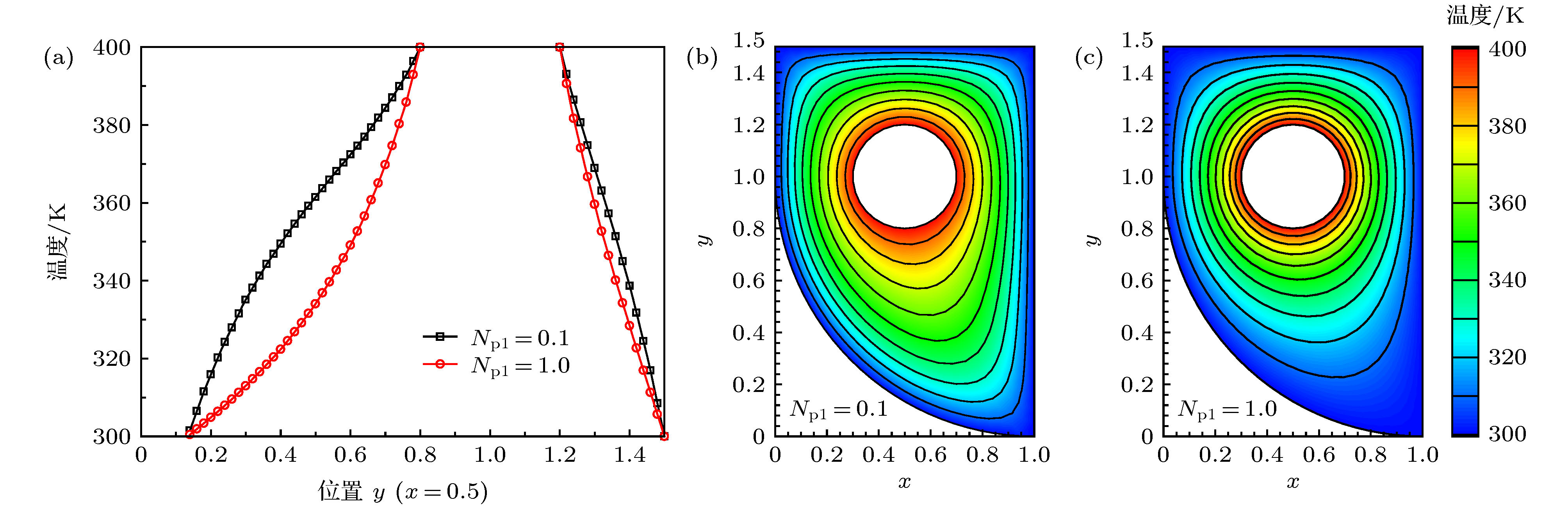 图 9 (a)普朗克数Npl = 0.1和1.0时内含圆形热边界的非规则形状介质中线上温度分布; (b) Npl = 0.1时介质温度分布; (c) Npl = 1.0时介质温度分布
Figure9. (a) Temperature distributions along the centerline of the irregular medium with an inner hot boundary; (b) temperature distribution within the computation domain for the case of Npl = 0.1; (c) temperature distribution within the computation domain for the case of Npl = 1.0.
在中心线上的同一位置处, 普朗克数Npl = 0.1对应的介质温度总是高于Npl = 1.0对应的介质温度. 这是由于当Npl = 0.1时, 辐射传热作用显著, 相同位置的辐射源项较强, 因此介质温度更高. 图9(b)和图9(c)所示分别为同普朗克数Npl = 0.1和 1.0条件下的介质温度分布的等值线图, 图9中相邻两条等值线之间的温度差为10 K. 由图9(b)和图9(c)的对比结果可知, 当普朗克数Npl = 0.1时, 强烈的辐射效应能够使高温圆环能量传播得更远, 因此介质内的能量分布更加均匀; 当普朗克数Npl = 1.0时, 显著的导热效应导致温度从高温圆环向外迅速降低, 因此外部边界附近较大范围内的介质温度处于较低水平.
进一步考虑如图10(a)所示的内含两个高温圆环的矩形介质, 该模型可用来研究两个高温管道及其所处环境之间的辐射导热耦合换热. 矩形介质边长为Lx × Ly = 1.0 m × 1.0 m, 内部圆环半径为R = 0.1 m, 圆心位置分别为(x, y) = (0.3 m, 0.3 m)和(x, y) = (0.7 m, 0.7 m). 矩形介质边界和圆环边界之间充满衰减系数为β = 1.0 m–1的参与性介质, 内部两个圆形边界温度均为400 K, 其他边界温度为300 K, 所有壁面均为黑壁面且发射率为ε = 1.0. 计算区域离散为图10(b)所示的1262个三角形单元、方向离散为Nθ × Nφ = 20 × 40条件下所得到的结果达到了网格无关性的要求, 采用DFEM求解本算例所需时间为131.75 s.
 图 10 内含两个圆形热边界的矩形介质 (a)结构示意图; (b)网格划分
Figure10. The medium the square medium with two circular hot boundaries: (a) Geometry sketch; (b) spatial discr etization.
在不同普朗克数Npl = 0.1和 1.0条件下, 中线x = 0.5上的温度分布如图11(a)所示, 可知介质中线温度在y = [0, 0.3]逐渐升高且温度变化剧烈程度逐渐降低, 再y = [0.3, 0.7]的介质保持较高的温度, 在y = [0.7, 1.0]逐渐降低. 在同一位置处, Npl = 0.1对应的介质温度高于Npl = 1.0对应的介质温度, 说明辐射效应作用对该模型中线上的介质温度具有显著的提升作用. 图11(b)和图11(c)所示分别为同普朗克数Npl = 0.1和 1.0条件下计算区域内温度分布的等值线图, 相邻两条等值线之间的温度差为5 K. 由图11(b)和图11(c)所示结果可知, 介质中心点位置(x, y) = (0.5 m, 0.5 m)周围存在一个温度梯度较小的区域, 且普朗克数越小, 该区域的面积越大. 以上结果表明辐射效应会弱化中心点位置处的温度梯度, 而导热效应则会强化该位置处的温度梯度.
 图 11 (a)普朗克数Npl = 0.1和1.0时内含两个圆形热边界的矩形介质中线上温度分布; (b) Npl = 0.1时介质温度分布; (c) Npl = 1.0时介质温度分布
Figure11. (a) Temperature distributions along the centerline of the square medium with two circular hot boundaries; (b) temperature distribution within the computation domain for the case of Npl = 0.1; (c) temperature distribution within the computation domain for the case of Npl = 1.0
