关键词:J积分;塑性断裂;半解析公式;能量等效假设;I型裂纹 Abstract The J-integral to characterize the singular level of the stress and strain field at the crack tip is definite and rigorous and is a basic parameter of elastoplastic fracture mechanics. The calculation of J-integral mainly depends on the plastic factor method and the finite element method at present. For theoretical predicting and testing of material fracture toughness, it is important and difficult to obtain analytical expressions about J-integral-load and load-displacement relations of cracked components. The most widely used test for structure integrity evaluation with J-integral is the ductile fracture toughness of type-I cracked specimens. Here, based on the Chen-Cai energy equivalence hypothesis, a unified characterization method of J-integral-load and load-displacement relation is proposed for six Mode-I cracked components which are commonly used in fracture toughness test under the plane strain condition. Then, the undetermined parameters of the engineering semi-analytical formulas of the J-integral-load and the load-displacement relations are obtained by a small amount of finite element analysis. The results show that the J-integral-load and load-displacement relation predicted by the unified semi-analytical formulas are in good agreement with those from finite element method. The engineering semi-analytical J-integral-load formula, which contains the elastic modulus, stress strength coefficient and strain hardening exponent of materials, can be widely adapted for different materials. And the J-integral value corresponding to arbitrary load points can be easily obtained by the formula. The presented novel method is convenient to establish the engineering semi-analytical formulas of J-integral-load and load-displacement relations for various type-I cracked components or specimens.
显示原图|下载原图ZIP|生成PPT 图5预测与计算的CT全塑性载荷-位移曲线比较 -->Fig. 5Comparison of fully plastic load-displacement curves predicted by formula and those from FEA for CT specimen -->
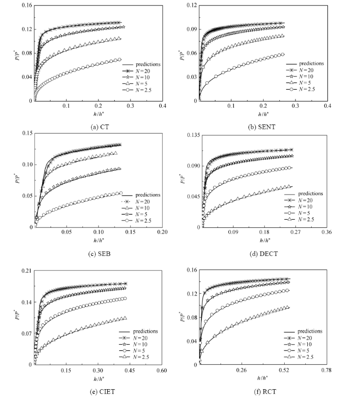
同理,本文还得到了SEB和SENT等其他5种试样 积分统一公式的未知参数,表2给出了其参数数值,图6给出了SEB、SENT等试样 载荷位移曲线公式预测与有限元结果对比,图7给出了各试样构元在 MPa 2 000 MPa, 时统一公式对J积分的预测结果与有限元对比. Table 2 表 2 表 2各类裂纹构元的J积分统一公式参数 Table 2Unified formula parameters of J-integral for various cracked components
新窗口打开 显示原图|下载原图ZIP|生成PPT 图6式(19)预测的弹塑性条件下载荷位移曲线与有限元比较 -->Fig.6Comparison of elastoplastic load-displacement curves predicted by Eq.(19) with those from FEA -->
显示原图|下载原图ZIP|生成PPT 图7式(23)预测的J积分与有限元结果比较 -->Fig. 7Comparison of J-integral predicted by Eq.(23) with those from FEA -->
3 结 论
(1) 基于Chen-Cai能量等效假设,结合 积分能量定义式,提出了一种解析求解I型裂纹构元 积分的方法, 这种新方法 旨在针对一系列I型裂纹标准试样和非标准试样可以较易实现获得 积分半解析的表达式,以便用于测试和断裂问题的理性分析. (2)对于6种I型裂纹构元,通过有限元的计算给出了 积分-载荷和载荷-位移统一公式的参数;依靠 积分统一公式预测的 积分结果相较有限元结果都吻合较好. The authors have declared that no competing interests exist.
(HuHaiyan, ZhaoYonghui, HuangRui.Studies on aeroelastic analysis and control of aircraft structures .Chinese Journal of Theoretical and Applied Mechanics,2016, 48(1): 1-27 (in Chinese)) [本文引用: 1]
(LiuZhanli, ZhuangZhuo, MengQingguo, et al.Problems and challenges of mechanics in shale gas efficient exploitation .Chinese Journal of Theoretical and Applied Mechanics, 2017, 49(3): 507-516 (in Chinese)) [本文引用: 1]
[3]
KumarV, GermanMD, ShihCF.Engineering Approach for Elastic-plastic Fracture Analysis. General Electric Co., Schenectady, New York: Corporate Research and Development Dept., 1981 [本文引用: 1]
[4]
KumarV, GermanMDWWW.Development on Elastic-plastic Fracture Analysis (EPRI NP-3607). Palo Alto, California: Research & Development Center of EPRI, 1984 [本文引用: 1]
[5]
ZahoorA.Ductile Fracture Handbook. vols 1-3, EPRI NP-6301-D/N14- 1, Novetech Corp . and Electric Power Research Institute (Palo Alto, CA), 1989, 1990, 1991 [本文引用: 1]
[6]
RiceJR.A path independent integral and the approximate analysis of strain concentration by notches and cracks .Journal of Applied Mechanics, 1968, 35(2): 379-386 [本文引用: 1]
(JiXing.A critical review on criteria of fracture mechanics .Chinese Journal of Theoretical and Applied Mechanics, 2016, 48(4): 741-753 (in Chinese)) [本文引用: 1]
(GB/T 21143-2014. Metallic materials-unified method of test for determination of quasistatic fracture toughness. Beijing:Standards Press of China, 2015 (in Chinese)) [本文引用: 1]
[10]
ASTM E399-09. Standard test methods for linear-elastic plane-strain fracture toughness Klc of metallic materials . Annual Book of ASTM Standards: Vol.3.01. PhiladelPhia, PA: Ameriean Society for Testing and Materials, 2009 [本文引用: 1]
[11]
ASTM E1820-09. Standard test methods for measurement of fracture toughness// Annual Book of ASTM Standards: Vol.3.01. PhiladelPhia, PA: Ameriean Society for Testing and Materials, 2009 [本文引用: 1]
[12]
SunPJ, WangGZ, XuanFZ, et al.Three-dimensional numerical analysis of out-of-plane creep crack-tip constraint in compact tension specimens .International Journal of Pressure Vessels and Piping, 2012, 96: 78-89 [本文引用: 1]
[13]
TraoreY, PaddeaS, BouchardPJ, et al.Measurement of the residual stress tensor in a compact tension weld specimen .Experimental Mechanics, 2013, 53(4): 605-618 [本文引用: 1]
[14]
QuinoG, El YagoubiJ, LubineauG.Characterizing the toughness of an epoxy resin after wet aging using compact tension specimens with non-uniform moisture content .Polymer Degradation and Stability, 2014, 109: 319-326 [本文引用: 1]
[15]
FeddernG, MacherauchE.New specimen geometry for KIC measurements. Z .Metallkunde, 1973, 64(12): 882-884 [本文引用: 1]
[16]
SzkodoM, Bień A. Influence of laser processing of the low alloy medium carbon structural steel on the development of the fatigue crack .Surface and Coatings Technology, 2016, 296: 117-123 [本文引用: 1]
[17]
KlyszS, LisieckiJ, LeskiA, et al.Least squares method modification applied to the NASGRO equation .Journal of Theoretical and Applied Mechanics, 2013, 51(1): 3-13 [本文引用: 1]
[18]
ChiesaM, NyhusB, SkallerudB, et al.Efficient fracture assessment of pipelines. A constraint-corrected SENT specimen approach .Engineering Fracture Mechanics, 2001, 68(5): 527-547 [本文引用: 1]
[19]
KingklangS, UthaisangsukV.Plastic deformation and fracture behavior of X65 pipeline steel: Experiments and modeling .Engineering Fracture Mechanics, 2018, 191: 82-101 [本文引用: 1]
[20]
HerteléS, De WaeleW, VerstraeteM, et al.J-integral analysis of heterogeneous mismatched girth welds in clamped single-edge notched tension specimens .International Journal of Pressure Vessels and Piping, 2014, 119: 95-107 [本文引用: 1]
[21]
BaoC, CaiLX, DanC.Estimation of fatigue crack growth behavior for small-sized C-shaped inside edge-notched tension (CIET) specimen using compliance technique .International Journal of Fatigue, 2015, 81: 202-212 [本文引用: 1]
(DanChen, CaiLixun, BaoChen, et al.Normalization method used to determine fracture toughness with C-ring small sized specimen and its application .Journal of Mechanical Engineering, 2015,51(14):54-65 (in Chinese)) [本文引用: 1]
[23]
TreifiM, OyadijiSO, TsangDKL.Computations of the stress intensity factors of double-edge and centre V-notched plates under tension and anti-plane shear by the fractal-like finite element method .Engineering Fracture Mechanics, 2009, 76(13): 2091-2108 [本文引用: 1]
[24]
BucciRJ, ParisPC, LandesJD, et al.J integral estimation procedures //Fracture Toughness: Part II. ASTM International, 1972 [本文引用: 1]
[25]
ErnstHA, ParisPC, LandesJD.Estimations on J-integral and tearing modulus T from a single specimen test record //Fracture Mechanics. ASTM International, 1981 [本文引用: 1]
[26]
ZahoorA.Fracture of circumferentially cracked pipes .Journal of Pressure Vessel Technology, 1986, 108(4): 529-531 [本文引用: 1]
[27]
ZahoorA.Evaluation of J-integral estimation scheme for flawed throughwall pipes .Nuclear Engineering and Design, 1987, 100(1): 1-9 [本文引用: 1]
[28]
GoldmanNL, HutchinsonJW.Fully plastic crack problems: the center-cracked strip under plane strain .International Journal of Solids and Structures, 1975, 11(5): 575-591 [本文引用: 1]
[29]
ASTM E1820-15:International. Standard test method for measurement of fracture toughness . ASTM International, 2015 [本文引用: 1]
[30]
MerkleJG, CortenHT.A J-integral analysis for the compact specimen, considering axial force as well as bending effects . Paper no. 74, PVP 33. American Society for Testing and Materials, 1974 [本文引用: 1]
(BaoChen, CaiLixun, DanChen, et al.Ductile fracture behavior of small-sized CIET specimen considering crack front constraint effect .Journal of Mechanical Engineering, 2017, 53(2): 34-44 (in Chinese)) [本文引用: 1]
[32]
RiceJR.A path independent integral and the approximate analysis of strain concentration by notches and cracks .Journal of Applied Mechanics, 1968, 35(2): 379-386 [本文引用: 1]
[33]
ChenH, CaiLX.Theoretical model for predicting uniaxial stress-strain relation by dual conical indentation based on equivalent energy principle .Acta Materialia, 2016, 121: 181-189 [本文引用: 1]
[34]
ChenH, CaiLX.Unified elastoplastic model based on strain energy equivalence principle .Applied Mathematical Modelling, 2017, 52: 664-671 [本文引用: 1]
[35]
ChenH, CaiLX.Unified ring-compression model for determining tensile properties of tubular materials .Materials Today Communications, 2017, 13: 210-220 [本文引用: 1]
[36]
ChenH, CaiLX.Theoretical conversions of different hardness and tensile strength for ductile materials based on stress-strain curves .Metallurgical and Materials Transactions A, 2018, 49(4): 1090-1101 [本文引用: 1]
 , 陈辉
, 陈辉 显示原图|下载原图ZIP|生成PPT
 显示原图|下载原图ZIP|生成PPT
 显示原图|下载原图ZIP|生成PPT
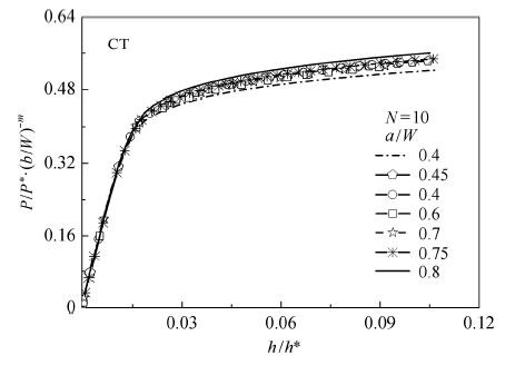 显示原图|下载原图ZIP|生成PPT
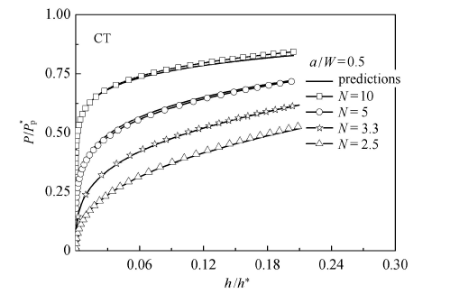 显示原图|下载原图ZIP|生成PPT
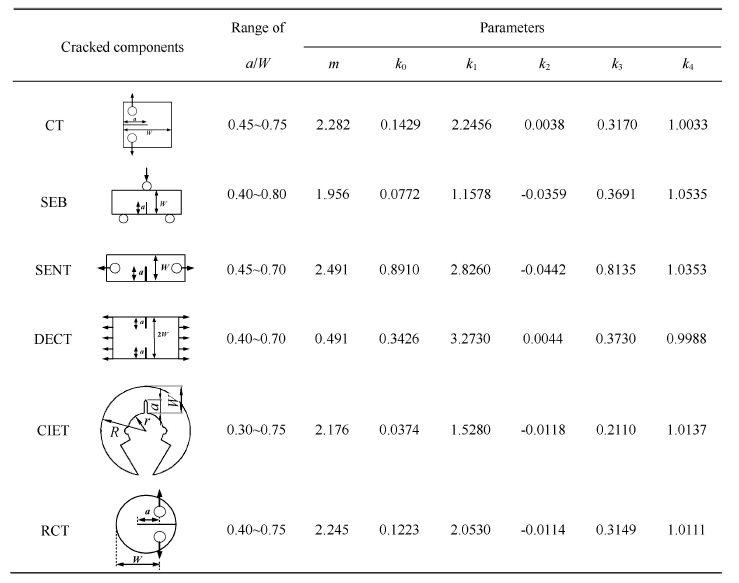
 显示原图|下载原图ZIP|生成PPT
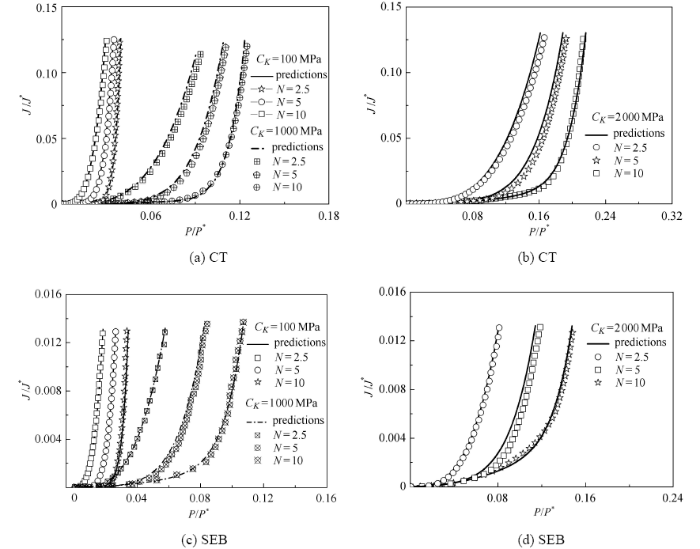 显示原图|下载原图ZIP|生成PPT