曹志坡1,梁乃兴1,曹源文2
(1.重庆交通大学 土木工程学院, 重庆 400074;2.重庆交通大学 机电与汽车学院, 重庆 400074)
摘要:
为了连续检测实际行车荷载作用下的路面结构承载力,以振动设备跳振工况下振动轮对地面的连续冲击荷载来模拟实际行车荷载作用,建立了考虑路面结构随振质量和各运动阶段初始相位角变化的“机器-地面”系统动力学模型,并将多层弹性体系的路面结构等效为用多层结构综合模量代表路面结构承载力的弹性半空间体. 通过对比分析不同统计时间长度内振动轮加速度负向极值的平均值和均方根值,提出以统计时间长度为4 s的振动轮加速度负向极值的平均值作为振动轮加速度信号的评价指标,得到不同型号的振动设备连续冲击不同承载力的路面结构时,振动轮加速度信号与路面结构综合模量之间的回归关系,并通过现场试验证明了方法的可行性. 研究结果表明:在跳振工况下,振动轮的加速度反馈信号与路面结构综合模量存在较好的回归关系;当路面结构综合模量变化时,振动设备的质量越小,振动轮的加速度信号指标变化越明显,检测的效果越好;可使用自重2 t,激振力100 kN的振动设备,对实际行车荷载作用下的路面结构承载力进行连续检测.
关键词: 道路工程 路面结构综合模量 连续冲击荷载 动力学模型 跳振工况 加速度信号
DOI:10.11918/201812167
分类号:U418.4
文献标识码:A
基金项目:云南省交通运输厅科技项目(云交科2017(A)15); 重庆市博士后资助(Xm2016126)
Method for continuously testing pavement structural composite modulus
CAO Zhipo1,LIANG Naixing1,CAO Yuanwen2
(1.School of Civil Engineering, Chongqing Jiaotong University, Chongqing 400074, China; 2. School of Mechanotronics & Vehicle Engineering, Chongqing Jiaotong University, Chongqing 400074, China)
Abstract:
To continuously test the bearing capacity of pavement structure under actual traffic loads, the continuous impact load of a vibration equipment with vibrating drum jumping on a pavement structure was used to simulate actual vehicle loads, and a dynamic model of “machine-ground” system was established considering the vibration mass of pavement structure and the change of initial phase angle in each movement stage. Then, a multi-layer elastic system of the pavement structure was equivalent to an elastic half-space body which uses the composite modulus of multi-layer structure to represent the bearing capacity of the pavement structure. By comparing and analyzing the mean and root-mean-square values of the negative acceleration extreme value of the vibrating drum in different statistical durations, the mean value in the statistical duration of 4 s was proposed as the index for evaluating the acceleration signal of the vibration drum. The regression relation between the acceleration signal of the vibration drum and the composite modulus of the pavement structure was obtained when different types of vibration device continuously impacted the pavement structure with different bearing capacities, and the feasibility of the method was proved by field test. Research results show that there was a good regression relationship between the acceleration signal of vibration drum and the composite modulus of road structure under jumping condition. With the changes of the pavement structural composite modulus, the smaller the mass of the vibration equipment was, the more obvious the change of the acceleration signal index of the vibration drum was, and the better the detection effect was. Therefore, a vibration equipment with the weight of 2 t and excitation force of 100 kN could be used to continuously test the bearing capacity of pavement structure under actual traffic loads.
Key words: road engineering pavement structural composite modulus continuous impact load dynamic model jump condition acceleration signal
曹志坡, 梁乃兴, 曹源文. 路面结构综合模量连续检测方法[J]. 哈尔滨工业大学学报, 2020, 52(3): 90-98. DOI: 10.11918/201812167.

CAO Zhipo, LIANG Naixing, CAO Yuanwen. Method for continuously testing pavement structural composite modulus[J]. Journal of Harbin Institute of Technology, 2020, 52(3): 90-98. DOI: 10.11918/201812167.

基金项目 云南省交通运输厅科技项目(云交科2017(A)15);重庆市博士后资助(Xm2016126) 作者简介 曹志坡(1987—),男,博士研究生;
梁乃兴(1957—),男,教授,博士生导师 通信作者 曹志坡,caozhipod630@sina.com 文章历史 收稿日期: 2018-12-26
Abstract Full text Figures/Tables PDF
路面结构综合模量连续检测方法
曹志坡1

 , 梁乃兴1, 曹源文2
 1. 重庆交通大学 土木工程学院, 重庆 400074;
2. 重庆交通大学 机电与汽车学院, 重庆 400074
收稿日期: 2018-12-26
基金项目: 云南省交通运输厅科技项目(云交科2017(A)15);重庆市博士后资助(Xm2016126)
作者简介: 曹志坡(1987—),男,博士研究生; 梁乃兴(1957—),男,教授,博士生导师
通信作者: 曹志坡,caozhipod630@sina.com
摘要: 为了连续检测实际行车荷载作用下的路面结构承载力,以振动设备跳振工况下振动轮对地面的连续冲击荷载来模拟实际行车荷载作用,建立了考虑路面结构随振质量和各运动阶段初始相位角变化的“机器-地面”系统动力学模型,并将多层弹性体系的路面结构等效为用多层结构综合模量代表路面结构承载力的弹性半空间体.通过对比分析不同统计时间长度内振动轮加速度负向极值的平均值和均方根值,提出以统计时间长度为4 s的振动轮加速度负向极值的平均值作为振动轮加速度信号的评价指标,得到不同型号的振动设备连续冲击不同承载力的路面结构时,振动轮加速度信号与路面结构综合模量之间的回归关系,并通过现场试验证明了方法的可行性.研究结果表明:在跳振工况下,振动轮的加速度反馈信号与路面结构综合模量存在较好的回归关系;当路面结构综合模量变化时,振动设备的质量越小,振动轮的加速度信号指标变化越明显,检测的效果越好;可使用自重2 t,激振力100 kN的振动设备,对实际行车荷载作用下的路面结构承载力进行连续检测.
关键词: 道路工程 路面结构综合模量 连续冲击荷载 动力学模型 跳振工况 加速度信号
Method for continuously testing pavement structural composite modulus
CAO Zhipo1

 , LIANG Naixing1, CAO Yuanwen2
 1. School of Civil Engineering, Chongqing Jiaotong University, Chongqing 400074, China;
2. School of Mechanotronics & Vehicle Engineering, Chongqing Jiaotong University, Chongqing 400074, China
Abstract: To continuously test the bearing capacity of pavement structure under actual traffic loads, the continuous impact load of a vibration equipment with vibrating drum jumping on a pavement structure was used to simulate actual vehicle loads, and a dynamic model of "machine-ground" system was established considering the vibration mass of pavement structure and the change of initial phase angle in each movement stage. Then, a multi-layer elastic system of the pavement structure was equivalent to an elastic half-space body which uses the composite modulus of multi-layer structure to represent the bearing capacity of the pavement structure. By comparing and analyzing the mean and root-mean-square values of the negative acceleration extreme value of the vibrating drum in different statistical durations, the mean value in the statistical duration of 4 s was proposed as the index for evaluating the acceleration signal of the vibration drum. The regression relation between the acceleration signal of the vibration drum and the composite modulus of the pavement structure was obtained when different types of vibration device continuously impacted the pavement structure with different bearing capacities, and the feasibility of the method was proved by field test. Research results show that there was a good regression relationship between the acceleration signal of vibration drum and the composite modulus of road structure under jumping condition. With the changes of the pavement structural composite modulus, the smaller the mass of the vibration equipment was, the more obvious the change of the acceleration signal index of the vibration drum was, and the better the detection effect was. Therefore, a vibration equipment with the weight of 2 t and excitation force of 100 kN could be used to continuously test the bearing capacity of pavement structure under actual traffic loads.
Keywords: road engineering pavement structural composite modulus continuous impact load dynamic model jump condition acceleration signal
路面结构承载力可以反映路面还能继续承受的轴载作用次数或者使用年限,代表了路面结构能够承受并分布车辆荷载的能力.路面结构承载力的检测是路面使用性能及结构性健康状况评价的重要组成部分,也是进行路面养护决策的重要依据[1],在道路的设计施工、运营管理阶段都有重要的意义.
1953年贝克曼(A.C.Benkelmen)发明了贝克曼梁式弯沉仪[2],设备简单,检测成本低,在工程实践中得到了广泛应用,但是其采用静态荷载,不能很好模拟实际行车荷载对路面结构的作用. 1960年代,稳态动力检测方法在美国AASHO试验中得到了应用,该方法对路面结构施加稳定的正弦波荷载,可检测路面在动态荷载作用下的弯沉,但是存在动力荷载小,且有较大静力预载的问题. 1970年代初期,法国、瑞典研制成功落锤式弯沉仪(FWD),对路面施加冲击荷载,可得到路面结构在冲击荷载下的弯沉盆信息,能较好地模拟实际行车荷载,是目前精度最高的路面弯沉检测设备[3],但是FWD只能实现单点测量,不能实现连续检测,测量时需要中断交通,限制了其在工程实践中的推广应用[4].目前,对FWD的研究大多集中在结构层模量反算及温度修正等方面[5-6],对荷载施加方式的研究却较少.
当振动设备在路面结构上跳振时,可以连续对路面结构施加冲击荷载,此类荷载可以很好地模拟实际的行车荷载[7],可以此为基础探索一种对路面结构连续施加冲击荷载并检测其承载力的方法.
对于振动设备的跳振工况,国内外学者进行了大量研究.文献[8]把振动设备的跳振过程分为符合和跳离运动,最早提出分阶段的机器-地面系统动力学模型.文献[9]考虑地面的粘弹塑性,建立了包括接触模型和跳离模型的四自由度机器-地面系统动力学模型.文献[10]关注了机器-地面系统在振动轮跳振过程中的混沌现象.
文献[11]较早关注了机器-地面系统的跳振现象,建立了振动轮接地和跳离阶段的动力学模型,并用数值方法进行了求解.文献[12]在对跳振现象的分阶段动力学模型研究中,考虑了跳离相位角和冲击相位角的变化.文献[13]考虑激振力的不同方向,建立了4自由度机器-地面系统动力学模型,对垂直、水平、斜向等不同方向激振力下振动轮的响应进行了分析.
目前,虽然国内外学者对机器-地面系统的跳振工况进行了大量研究,但主要集中在跳振工况的判定及如何避免跳振的产生[13-14],对跳振工况的利用研究较少.在建立跳振工况的动力学模型时,也大多认为振动轮每次冲击地面时激振器相位角为零,这不符合实际情况.因此本文根据动量守恒定律,建立了包括符合、跳离、冲击3个运动阶段的机器-地面系统动力学模型,着重考虑了各运动阶段初始相位角的变化,并给出了初始相位角的计算方法.
为了对跳振工况进行利用,提出以振动轮加速度负向极值的平均值为评价指标,得到路面结构承载力与该指标的关系,为实现路面结构承载力的连续检测提供理论依据.
1 机器-地面系统动力学模型及仿真参数 1.1 机器-地面系统动力学模型在建立机器-地面系统动力学模型时提出以下几个假设:1)各层路面结构均为弹性体;2)根据振动轮与地面接触状态,将模型分为符合、跳离、冲击3个阶段;3)冲击过程时间很短,系统符合动量守恒定律;4)振动轮与地面的接触符合赫兹接触理论;5)系统静平衡位置为原点,方向向下为正方向.因此建立机器-地面系统动力学模型如图 1所示.
Fig. 1
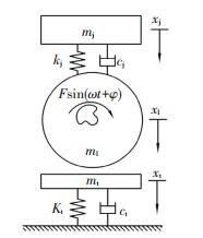 图 1 机器-地面系统跳振工况动力学模型 Fig. 1 Dynamic model of machine-ground system under jumping condition
 在运动初期,机器-地面系统处于符合运动阶段, 此时振动轮未发生跳振,与随振质量一起运动,可以忽略重力作用.当振动设备激振力F≥3(mj+ml)g,且振动轮速度及位移均小于0时,认为振动轮进入跳离运动阶段[14].该阶段振动轮与随振质量分离,此时地面与振动设备没有相互作用,重力作用不可忽略.当振动轮位移等于地面位移时,振动轮冲击地面.
各运动阶段激振器相位角的变化如图 2所示,图 2中曲线1为随振质量的位移曲线,曲线2为振动轮位移曲线,曲线3为激振器相位角随时间变化曲线. a点为系统结束第1次符合运动,进入跳离阶段时振动设备与地面的分离点,此时时间为ta,激振器相位角为φa; b点为系统结束第1次跳离阶段,进入冲击阶段时振动设备对地面的冲击点,同时b点也是系统进入第2次符合运动时振动设备与地面的结合点,此时时间为tb,激振器相位角为φb.
Fig. 2
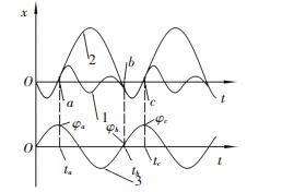 图 2 冲击相位角变化示意图 Fig. 2 Schematic of the impact phase angle changes
 建立系统三阶段动力学方程.符合阶段、跳离阶段、冲击阶段的动力学方程分别为
$\left\{ \begin{array}{l}{m_{\rm{j}}}{{\ddot x}_{\rm{j}}} + {k_{\rm{j}}}\left( {{x_{\rm{j}}} - {x_1}} \right) + {c_{\rm{j}}}\left( {{{\dot x}_{\rm{j}}} - {{\dot x}_1}} \right) = 0,\\\left( {{m_{\rm{l}}} + {m_{\rm{t}}}} \right){{\ddot x}_1} - {k_{\rm{j}}}\left( {{x_{\rm{j}}} - {x_1}} \right) - {c_{\rm{j}}}\left( {{{\dot x}_{\rm{j}}} - {{\dot x}_1}} \right) + \\\;\;\;\;\;{k_1}{x_1} + {c_1}{{\dot x}_1} = F\sin (\omega t + \varphi ).\end{array} \right.$ (1)
$\left\{ \begin{array}{l}{m_{\rm{j}}}{{\ddot x}_{\rm{j}}} + {k_{\rm{j}}}\left( {{x_{\rm{j}}} - {x_1}} \right) + {c_{\rm{j}}}\left( {{{\dot x}_{\rm{j}}} - {{\dot x}_1}} \right) = {m_{\rm{j}}}g,\\{m_{\rm{l}}}{{\ddot x}_1} - {k_{\rm{j}}}\left( {{x_{\rm{j}}} - {x_1}} \right) - {c_{\rm{j}}}\left( {{{\dot x}_{\rm{j}}} - {{\dot x}_1}} \right) = {m_1}g + \\\;\;\;\;\;\;F\sin (\omega t + \varphi ),\\{m_{\rm{t}}}{{\ddot x}_{\rm{t}}} + {k_{\rm{t}}}{x_{\rm{t}}} + {c_{\rm{t}}}{{\dot x}_{\rm{t}}} = 0.\end{array} \right.$ (2)
${v_1}(i + 1) = \frac{{{m_1}{v_1}(i) + {m_1}{v_1}(i)}}{{{m_1} + {m_{\rm{t}}}}}.$ (3)
式中:mj、ml、mt分别为机架、振动轮和地面随振质量,kg;kj为机架刚度,N/m;kt为地面等效刚度,N/m;cj为机架阻尼,N·s/m;ct为地面等效阻尼,N·s/m;xj、xl、xt分别为机架、振动轮和地面位移,m;F为激振力幅值,N;ω为激振器转动角速度,rad/s;φ为该阶段初始相位角,rad;vl(i)、vt(i)分别为系统结束第i次跳离运动阶段时振动轮和随振质量的速度;vl(i+1)为第i次冲击运动结束时振动轮与随振质量的速度.
当系统结束第j(j=0, 1, …, 2n-1)个运动阶段时,记时间为tj,则系统的相位角变化为
$\varphi (j + 1) = \text{rem}\left[ {{t_j},T} \right] \times 2{\rm{ \mathsf{ π} }}T.$ (4)
式中:rem[tj, T]表示tj对T取余数,T为激振器转动周期.
引入变量:
${m_{\rm{h}}} = {m_1} + {m_{\rm{t}}},{\eta _1} = \frac{{{m_{\rm{j}}}}}{{{m_{\rm{h}}}}},{\eta _2} = \frac{{{m_{\rm{j}}}}}{{{m_1}}},{\omega _{\rm{j}}} = \sqrt {\frac{{{k_{\rm{j}}}}}{{{m_{\rm{j}}}}}} ,$
${\omega _{\rm{h}}} = \sqrt {\frac{{{k_{\rm{t}}}}}{{{m_{\rm{h}}}}}} ,{\omega _{\rm{t}}} = \sqrt {\frac{{{k_{\rm{t}}}}}{{{m_{\rm{t}}}}}} ,{\xi _{\rm{j}}} = \frac{{{c_{\rm{j}}}}}{{2\sqrt {{k_{\rm{j}}}{m_{\rm{j}}}} }},$
${\xi _{\rm{h}}} = \frac{{{c_{\rm{t}}}}}{{2\sqrt {{k_{\rm{t}}}{m_{\rm{h}}}} }},{\xi _{\rm{t}}} = \frac{{{c_{\rm{t}}}}}{{2\sqrt {{k_{\rm{t}}}{m_{\rm{t}}}} }},\lambda = \frac{F}{{{m_{\rm{h}}}}},\beta = \frac{F}{{{m_{\rm{l}}}}}.$
记系统第i(i=1, 2, …, n)次符合运动的开始时间为ti,该阶段内机架和振动轮的位移分别为xj(i)和xl(i),此时系统初始条件为
$\left\{ \begin{array}{l}{\left. {{x_{\rm{j}}}\left( 1 \right)} \right|_{0 - }} = {\left. {{{\dot x}_{\rm{j}}}\left( 1 \right)} \right|_{0 - }} = 0,\\{\left. {{x_1}\left( 1 \right)} \right|_{0 - }} = {\left. {{x_1}\left( 1 \right)} \right|_{0 - }} = {\left. {{{\dot x}_1}\left( 1 \right)} \right|_{0 - }} = {\left. {{{\dot x}_1}\left( 1 \right)} \right|_{0 - }} = 0,\\{\varphi _0} = 0.\end{array} \right.$
对式(1)进行求解,得
${x_{\rm{j}}}\left( i \right) = \lambda \sqrt {\frac{{{c^2} + {d^2}}}{{{a^2} + {b^2}}}} \sin \left( {\omega {t_i} - {\psi _1} + {\varphi _{2i - 2}}} \right),$
${x_1}\left( i \right) = \lambda \sqrt {\frac{{{l^2} + {f^2}}}{{{a^2} + {b^2}}}} \sin \left( {\omega {t_i} - {\psi _2} + {\varphi _{2i - 2}}} \right),$
${\psi _1} = \arctan \frac{{bc - ad}}{{ac + bd}},$
${\psi _2} = \arctan \frac{{lb - fa}}{{la + fb}}.$
式中:
$\begin{array}{l}a = \left[ {\left( {{\eta _1} - 4{\eta _1}\xi _{\rm{j}}^2 + 1} \right)\omega _{\rm{j}}^2 + \left( {4{\xi _{\rm{h}}}{\omega _{\rm{h}}} + 2{\eta _1}} \right){\xi _{\rm{j}}}{\omega _{\rm{j}}} + } \right.\\\;\;\;\left. {\omega _{\rm{h}}^2 - {\omega ^2}} \right]{\omega ^2} - \omega _{\rm{h}}^2\omega _{\rm{j}}^2 - 2{\eta _1}{\xi _{\rm{j}}}\omega _{\rm{j}}^3,\end{array}$
$\begin{array}{l}b = \left( {2{\xi _{\rm{j}}}{\omega _{\rm{j}}} + 2{\xi _{\rm{h}}}{\omega _{\rm{h}}}} \right){\omega ^3} + \left( {2{\eta _1}{\xi _{\rm{j}}}\omega _{\rm{j}}^3 - 4{\eta _1}\xi _{\rm{j}}^2\omega _{\rm{j}}^2 - } \right.\\\;\;\;\left. {2{\xi _{\rm{j}}}{\omega _{\rm{j}}}\omega _{\rm{h}}^2 - 2{\xi _{\rm{h}}}{\omega _{\rm{h}}}\omega _{\rm{j}}^2} \right)\omega ,\end{array}$
$c = - \omega _{\rm{j}}^2,$
$d = f = - 2{\xi _{\rm{j}}}{\omega _{\rm{j}}}\omega ,$
$l = {\omega ^2} - \omega _{\rm{j}}^2.$
其中φ2i-2计算如式(4)所示.
记系统第i次跳离运动的开始时间为Ti,该阶段内机架和振动轮的位移分别为Xj(i)和Xl(i),系统第i次跳离阶段初始条件为
$\left\{ \begin{array}{l}{\left. {{X_{\rm{j}}}\left( i \right)} \right|_{{T_i} - }} = {\left. {{x_{\rm{j}}}\left( i \right)} \right|_{{T_i} + }},\\{\left. {{{\dot X}_{\rm{j}}}\left( i \right)} \right|_{{T_i} - }} = {\left. {{{\dot x}_{\rm{j}}}\left( i \right)} \right|_{{T_i} + }},\\{\left. {{X_1}\left( i \right)} \right|_{{T_i} - }} = {\left. {{X_{\rm{t}}}\left( i \right)} \right|_{{T_i} - }} = {\left. {{x_1}\left( i \right)} \right|_{{T_i} + }} = 0,\\{\left. {{{\dot X}_1}\left( i \right)} \right|_{{T_i} - }} = {\left. {{{\dot X}_{\rm{t}}}\left( i \right)} \right|_{{T_i} - }} = {\left. {{{\dot x}_1}\left( i \right)} \right|_{{T_i} + }},\\{\left. {\varphi \left( i \right)} \right|_{{T_i} - }} = \varphi \left( {2i - 1} \right).\end{array} \right.$
令
${X_{\rm{j}}}\left( i \right) = \sqrt {\frac{{{r^2} + {s^2}}}{{{p^2} + {q^2}}}} \sin \left( {\omega {T_i} - {\psi _3} + {\varphi _{2i - 1}}} \right),$
${X_1}(i) = \sqrt {\frac{{{u^2} + {z^2}}}{{{p^2} + {q^2}}}} \sin \left( {\omega {T_i} - {\psi _4} + {\varphi _{2i - 1}}} \right),$
${X_{\rm{t}}}(i) = {{\rm{e}}^{ - {\xi _{\rm{t}}}{\omega _{\rm{t}}}{T_i}}}\left[ {{C_1}{{\rm{e}}^{i\left( {{\omega _{\rm{r}}}{T_i} + {\varphi _{2i - 1}}} \right)}} + {C_2}{{\rm{e}}^{ - i\left( {{\omega _{\rm{r}}}{T_i} + {\varphi _{2i - 1}}} \right)}}} \right],$
${\psi _3} = \arctan \frac{{qr - ps}}{{pr + qs}},$
${\psi _4} = \arctan \frac{{uq - zp}}{{up + zq}}.$
式中:
$p = \left( {2{\eta _2} + 1} \right)\omega _{\rm{j}}^2{\omega ^2} - {\omega ^4},$
$q = 2\left( {{\eta _2} + 1} \right){\xi _{\rm{j}}}{\omega _{\rm{j}}}{\omega ^3},$
$r = - \left( {2{\eta _2}g + g + \beta } \right)\omega _{\rm{j}}^2 + g{\omega ^2},$
$s = z = - 2\left( {{\eta _2}g + g + \beta } \right){\xi _{\rm{j}}}{\omega _{\rm{j}}}\omega ,$
$u = (g + \beta ){\omega ^2} - \left( {2{\eta _2}g + g + \beta } \right)\omega _{\rm{j}}^2.$
其中C1、C2可由跳离运动初始条件求得,φ2i-1计算如式(4)所示.
当系统结束第i次跳离阶段,进入第i+1次符合阶段时,振动轮位移等于地面位移,振动轮速度计算如式(3)所示,则第i+1个符合阶段的初始条件为
$\left\{ \begin{array}{l}{\left. {{x_{\rm{j}}}(i + 1)} \right|_{{t_{i + 1}} - }} = {\left. {{X_{\rm{j}}}(i)} \right|_{{t_{i + 1}} + }},\\{\left. {{{\dot x}_{\rm{j}}}(i + 1)} \right|_{{t_{i + 1}} - }} = {\left. {{X_{\rm{j}}}(i)} \right|_{{t_{i + 1}} + }},\\{\left. {{x_1}(i + 1)} \right|_{{t_{i + 1}} - }} = {\left. {{X_1}(i)} \right|_{{t_{i + 1}} + }} = {\left. {{X_t}(i)} \right|_{{t_{i + 1}} + }},\\{\left. {{{\dot x}_1}(i + 1)} \right|_{{t_{i + 1}} - }} = \frac{{{{\left. {{m_1}{{\dot X}_1}(i)} \right|}_{{t_{i + 1}} + }} + {{\left. {{m_t}{{\dot X}_t}(i)} \right|}_{{t_{i + 1}} + }}}}{{{m_1} + {m_t}}},\\{\left. {\varphi (i)} \right|_{{t_{i + 1}} - }} = \varphi (2i).\end{array} \right.$
1.2 路面结构等效换算路面结构是一个多层弹性层状体系,如图 3(a)所示.根据弹性层状体系理论,当已知路面结构各层的弹性模量和厚度时,可根据弯沉等效原则将多层路面结构等效成一个弹性半空间体[15],如图 3(b)所示,其弹性模量称为多层结构综合模量,以下简称为综合模量.
Fig. 3
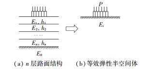 图 3 多层弹性层状体系换算示意图 Fig. 3 Schematic of conversion of multi-layer elastic layered system
 图 3(a)为层数为n的路面结构,顶面作用一个均布荷载P,E1、h1分别为第1层路面结构的弹性模量和厚度,并依次类推.假设路面结构层间连续,可根据式(5)可将路面结构等效成弹性模量为Ex、厚度为hx的整体.
$\left\{ \begin{array}{l}{E_{\rm{x}}} = \frac{{h_1^2{E_1} + h_2^2{E_2}}}{{h_1^2 + h_2^2}},\\{D_{\rm{x}}} = \frac{{{{\left( {{h_1} + {h_2}} \right)}^2}}}{4}{\left( {\frac{1}{{{E_1}{h_1}}} + \frac{1}{{{E_2}{h_2}}}} \right)^{ - 1}} + \\\;\;\;\;\;\frac{{h_1^3{E_1} + h_2^3{E_2}}}{{12}},\\{h_{\rm{x}}} = {\left( {\frac{{12{D_{\rm{x}}}}}{{{E_{\rm{x}}}}}} \right)^{\frac{1}{3}}}.\end{array} \right.$ (5)
等效后的路面结构与土基之间的关系如式(6)所示,得出弹性半空间体结构的综合模量Et, 如图 3(b)所示.
$\frac{{{E_{\rm{t}}}}}{{{E_0}}} = Ah_{\rm{x}}^B{\left( {\frac{{{E_{\rm{x}}}}}{{{E_0}}}} \right)^{\frac{1}{3}}}.$ (6)
式中:
$A = 6.37\left[ {1 - 1.53{{\left( {\frac{{{E_{\rm{x}}}}}{{{E_0}}}} \right)}^{ - 0.48}}} \right],$
$B = 1 - 1.44{\left( {\frac{{{E_{\rm{x}}}}}{{{E_0}}}} \right)^{ - 0.55}}.$
1.3 动力学模型仿真参数取值文献[16-17]采用动力半空间理论中的方程对等法,推导出了地面刚度与综合模量的等效换算公式:
${K_i} = \frac{{2{E_i}{r_i}}}{{\left( {1 - \sigma _i^2} \right)}}.$ (7)
式中Ei、σi分别为各层材料弹性模量和泊松比,ri为各层压力传递的等效圆半径.
当振动轮半径为R,地面材料内摩擦角为β,振动轮宽度为L时,接地面等效圆半径为
${r_1} = 0.8\sqrt {\sin \beta } \sqrt {RL} .$ (8)
推导出地面随振质量mt计算公式[16-17]为
${m_{\rm{t}}} = \left( {\xi - 1} \right){m_1}.$ (9)
式中ξ为随振质量附加系数,
$\xi = 1.056 - 7.25 \times {10^{ - 4}}b,$ (10)
其中b为无量纲质量比,b=ml/(ρr13),ρ为路面面层材料密度.
推导出地面等效阻尼计算公式[16-17]为
${c_{\rm{t}}} = 2\left( {0.265 - 2.33 \times {{10}^{ - 3}}b} \right){\omega _{\rm{n}}}{m_{\rm{t}}}.$ (11)
式中ωn为随振质量固有频率,ωn=(K/mt)0.5.
为了研究不同振动设备在路面结构上跳振时,其振动轮加速度信号与路面结构综合模量之间的关系,使用徐工XS261、洛建LSS220H、戴纳派克CA250D三种不同总质量的振动压路机,并参考FWD检测时对路面结构施加的荷载[18],自定义了一个自重2 t,激振力100 kN的振动设备,分别计算出仿真模型中各振动设备对应的路面参数,得到机器-地面系统动力学仿真模型的主要参数见表 1.表中mz、mq分别为压路机总质量和前轮分配质量,I为上下车质量分配比,f为振动频率,F为激振力,D为振动轮直径,Kj为机架刚度,Cj为机架阻尼,mt为地面随振质量,Ct为地面阻尼.
表 1
XS261 26 000 17 000 1:1 27/32 410/300 2 130 1 600 5.52 36 500 132.88 16 386
LSS220H 20 000 10 000 1:1 28/35 360/280 2 130 1 600 3.74 32 000 121.71 19 220
CA250D 12 100 6 300 1:1 33/33 248/121 2 130 1 523 3.26 29 400 119.06 22 470
自定义2 t 2 000 2 000 1:1 35 100 2 130 1 600 1.04 23 000 83.41 26 259
表 1 仿真模型主要参数 Tab. 1 Main parameters of simulation model
2 动力学模型仿真与结果分析 2.1 振动轮加速度评价指标采用四阶龙格-库塔方法建立式(1)~(4)的仿真模型,取路面结构综合模量Et=30、45 MPa,对不同型号的振动设备以低频高幅工作频率作业进行仿真,得到了振动轮运动相图的庞加莱截面不动点及加速度曲线,以洛建LSS220H为例,其仿真结果如图 4所示.
Fig. 4
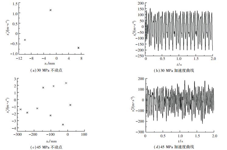 图 4 不同路面结构综合模量下振动轮加速度信号庞加莱截面不动点及加速度曲线 Fig. 4 Fixed points on the Poincaré section and acceleration curves of the acceleration signal of vibration drum jumping on pavement structures with different composite modulus
 由图 4(a)、4(b)可以看出,当路面结构综合模量为30 MPa时,相图有3个不动点,系统作周期3的拟周期运动,振动轮发生了跳振,加速度信号基本稳定,但其加速度负向极值有较大的起伏,单一的加速度负向极值已不能用来对加速度信号进行评价.
由图 4(c)、4(d)可知当路面结构综合模量增大到45 MPa时,系统进入混沌运动状态,振动轮的加速度负向极值剧烈变化,需要选择一个合适的统计指标来评价振动轮加速度信号,研究其与路面结构综合模量之间是否存在关系.
振动轮冲击路面时,加速度在数值上为负,将加速度信号小于0时曲线上的极小值称为加速度负向极值,如图 5中菱形点所示. 图 5为统计时间长度2 s时的振动轮加速度信号曲线,将曲线上菱形点的个数记为n,第i个菱形点的值记为ai.将不同统计时间长度t(t=2, 4, 6, 8, 10 s)内的加速度负向极值点的平均值和均方根值分别记为am(j)和ar(j),j=1、2、3、4、5,计算公式分别为
Fig. 5
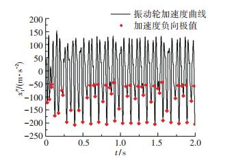 图 5 加速度负向极值示意图 Fig. 5 Schematic of negative acceleration extreme value
 ${a_{\rm{m}}}\left( j \right) = \frac{1}{n}\sum\limits_{i = 1}^n {{a_i}} ,$ (12)
${a_{\rm{r}}}\left( j \right) = \sqrt {\frac{1}{n}\sum\limits_{i = 1}^n {a_i^2} } .$ (13)
对不同型号振动设备、不同路面结构综合模量的“机器-地面”系统进行了仿真,得到不同统计时间长度对应的加速度负向极值点的平均值am(j)和均方根值ar(j), 如图 6所示.
Fig. 6
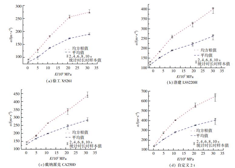 图 6 不同统计时间长度下不同设备振动轮加速度信号统计指标对比 Fig. 6 Comparison of acceleration signal statistics indexes of vibration drum for different equipment under different statistical time lengths
 由图 6可以看出,随着路面结构综合模量的增大,不同型号振动设备的振动轮加速度负向极值的平均值am(j)和均方根值ar(j)均增大.而且当统计时间长度变化时,am(j)的分散程度明显小于ar(j),因此选择am(j)作为不同统计时间长度内振动轮加速度信号的统计指标.为了确定最佳的统计时间长度,对20个不同振动设备、不同路面结构综合模量参数组合的机器-地面系统仿真结果进行了进一步分析,结果显示,当统计时间长度分别为4、6、8、10 s时,与am(j)样本均值偏差最小的分别有8、5、1、6个,为了兼顾准确性和运算速度,选择统计时间长度为4 s时加速度负向极值点的平均值作为振动轮加速度的评价指标,记为a.
2.2 振动轮加速度信号与路面结构综合模量之间的关系仿真结果为了研究振动设备跳振工况下振动轮加速度信号与路面结构综合模量之间关系,在路面基层的回弹模量常见取值在15~90 MPa之间,每隔15 MPa取一个值,在路面结构综合模量取值在100~3 100 MPa之间[19],每隔200 MPa取一个值进行仿真计算,得到路面结构综合模量与加速度信号之间关系如图 7所示. 图 7给出了当使用戴纳派克CA250D、洛建LSS220H、徐工XS261型振动压路机和自定义机械作为振动设备时,路面结构综合模量与振动轮加速度信号的回归关系.
Fig. 7
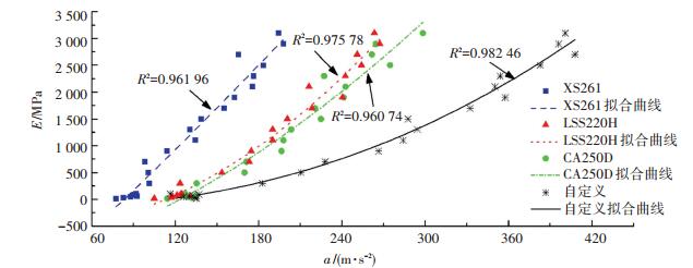 图 7 路面结构综合模量与加速度信号关系 Fig. 7 Relationship between pavement structural composite modulus and acceleration signal
 徐工XS261:
$E = 13.76418{a^{1.10826}} - 1846.72022.$ (14)
洛建LSS220H:
$E = 0.03805{a^{2.05042}} - 616.51002.$ (15)
戴纳派克CA250D:
$E = 0.42754{a^{1.61899}} - 1038.45521.$ (16)
自定义2 t:
$E = 0.00306{a^{2.30306}} - 169.40595.$ (17)
由图 7可知,不同型号的振动设备在不同综合模量的路面结构上跳振时,均存在较好的回归关系,且当路面结构综合模量变化时,振动设备质量越小,振动轮的加速度信号指标变化越明显,检测的效果越好.当使用自定义的自重2 t的振动设备进行仿真时,其加速度统计值小于420 m/s2,对路面的冲击力为8.4×103 kN,小于洛建LSS220H型振动压路机接地振压工况对路面结构的动态作用力1.2×10⁴ kN,此时不会破坏路面结构.因此自重2 t,激振力100 kN的振动设备的跳振工况可以用来检测路面结构综合模量.与当前广泛研究的压实度自动检测系统不同,当使用振动设备的跳振工况对不同综合模量的路面结构进行检测时,可根据振动轮的加速度信号直接换算出路面结构的综合模量,而不需要在试验路段进行标定.
3 试验验证 3.1 动力学模型正确性试验验证试验所用振动设备为洛建LSS220H型压路机,数据采集系统采用东华DH5902动态数据采集仪和ICP压电式DH186加速度传感器,采样频率1 000 Hz,灵敏度10.13 mV/(m·s-2),加速度传感器安装在振动轮上.试验在已压实的土基上进行,土质为粘性土,其土体密度ρ=1.753×103 kg/m3,土的内摩擦角β=8.836°,根据文献[18],土基泊松比σ=0.4,使用承载板方法检测得土基回弹模量为52.5 MPa.试验现场和加速度传感器安装位置分别如图 8、9所示.
Fig. 8
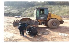 图 8 试验现场 Fig. 8 Test site
 Fig. 9
 图 9 加速度传感器安装位置 Fig. 9 Mounting position of acceleration sensor
 洛建LSS220H型振动压路机有两种工作频率,分别为高频低幅(35 Hz/280 kN)和低频高幅(28 Hz/ 360 kN).振动压路机分别以高频低幅和低频高幅在压实土基上振动,采集到的振动轮加速度反馈信号如图 10、11所示.由于数据都是从起振阶段开始采集的,因此振动轮加速度信号在20 s后才开始达到稳定阶段.由图 10(a)可以看出当振动压路机以高频低幅运行时,系统稳定后振动轮的加速度信号幅值基本稳定.由图 10(b)可知当振动设备以高频低幅在压实土基上作业时,实测振动轮加速度信号与机器-地面系统动力学模型的仿真仿真结果基本一致,误差不超过10%,因此该力学仿真模型可以很好地模拟振动设备不发生跳振时的工作状态.
Fig. 10
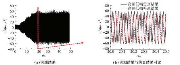 图 10 高频低幅振动轮加速度实测结果与仿真结果对比 Fig. 10 Comparison between the measured results and the simulation results of vibration drum acceleration signal in high frequency and low amplitude
 Fig. 11
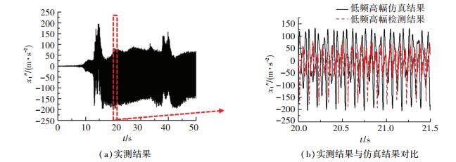 图 11 低频高幅振动轮加速度实测结果与仿真结果对比 Fig. 11 Comparison between the measured results and the simulation results of vibration drum acceleration signal in low frequency and high amplitude
 而由图 11(a)可以看出当振动压路机以低频高幅运行时,系统稳定后振动轮加速度信号幅值先经过一个稳定阶段,然后产生了一定的上下起伏.这是由于振动压路机是在原地跳振,先是将土基进一步压实,此时振动轮加速度信号幅值增大;然后稳定了一段时间,此时信号幅值基本稳定;继续在已压实的土基上振压,产生了过压,破坏了已压实的土基,造成土基松散,加速度幅值信号减小.再对松散后的土基进行压实,振动轮的加速度信号幅值随土基刚度的变化也产生了相应的起伏.
由图 11(b)可以看出,当振动设备以低频高幅在压实土基上跳振时,系统呈现了明显的非线性特征.振动轮正向加速度幅值仿真结果明显大于实测结果,这是因为振动轮与机架之间使用橡胶减振器连接,橡胶减振器有很强的非线性特性[20],吸收了较多的冲击能量.研究中为了简化模型,未考虑橡胶减振器的非线性特性.虽然振动轮冲击机架时的仿真结果与实测值存在误差,但是振动轮冲击地面时的仿真结果与实测结果之间的误差小于10%,说明该机器-地面系统动力学模型能较好地模拟系统跳振时振动轮与地面之间的相互作用.
3.2 振动轮加速度信号与路面结构综合模量关系准确性试验验证为了验证仿真得到的振动轮加速度信号与路面结构综合模量的回归关系,使用洛建LSS220H型振动压路机的低频高幅档位对两种不同土基和一种路面结构进行了检测.由于FWD检测到的动态模量与BB梁的检测结果存在较好的相关关系[21],因此在检测路面结构综合模量时使用了可反映路面结构综合模量的BB梁检测方法.
把根据加速度检测结果插值得到的路面结构综合模量记为Ec, 根据BB梁的检测结果换算得到的路面结构综合模量记为Eb,Ec与Eb两者之差与Eb的比值记为误差W,如表 2所示.检测时半刚性基层沥青路面弯沉检测时地表温度为10 ℃,前5日内平均气温为6.5 ℃,查表得温度修正系数为1.1.
表 2
粘土土基 承载板 — 52.5 118.50 63.24 20.45
粉土土基 BB梁 0.855 104.3 124.79 139.28 33.54
半刚性基层沥青路面 BB梁 0.242 — 258.23 2 740.70 —
表 2 插值结果与实测结果对比 Tab. 2 Comparison between the interpolation results and the measured results
由表 2可知,使用振动设备跳振工况下振动轮加速度信号检测土基承载力时,误差基本满足工程要求.检测半刚性沥青路面时,插值结果也基本符合一般规律.因此,可以使用振动轮加速度信号连续检测路面结构承载力.
4 结论1) 建立了同时考虑地面随振质量和初始相位角变化的机器-地面系统动力学模型,并通过现场试验验证了模型的正确性.经过对比系统跳振和不跳振工况下的模型仿真结果与实测结果,误差均不超过10%,说明该模型可以用来研究跳振工况下的振动轮加速度信号与路面结构综合模量之间的关系.
2) 随着路面结构综合模量的增大,机器-地面系统由相对稳定的拟周期运动状态逐渐进入混沌运动状态,但是振动轮加速度负向极值的统计值仍有一定规律.通过分析,提出以统计时间长度4 s的振动轮加速度负向极值的平均值作为研究振动轮加速度信号与路面结构综合模量之间关系的评价指标.
3) 由仿真结果可知,振动设备跳振工况下振动轮的加速度信号与路面结构综合模量存在较好的回归关系,可使用自重2 t,激振力100 kN的振动设备的跳振工况连续检测路面结构综合模量.
4) 实测振动轮加速度信号插值得到的路面结构承载力结果与传统方法检测结果相比,误差基本符合工程要求,因此振动设备跳振工况下的振动轮加速度信号与路面结构综合模量之间的回归关系是准确的.
参考文献
[1] RABAIOTTI C, PUZRIN A, CAPREZ M, et al. Pavement structural health evaluation based on inverse analysis of three dimensional deflection bowl[J]. International Journal of Pavement Engineering, 2013, 14(4): 374. DOI:10.1080/10298436.2012.684055
[2] American Association of State Highway and Transportation Officials. AASHTO guide for design of pavement structures[M]. Washington DC: AASHTO, 1993.
[3] PRIMUSZ P, PETERFALVI J, MARKO G, et al. Effect of pavement stiffness on the shape of deflection bowl[J]. Acta Silv Lign Hung, 2015, 11(1): 39. DOI:10.1515/aslh-2015-0003
[4] ELBAGALATI O, ELESIFI M A, GASPARD K, et al. Prediction of in-service pavement structural capacity based on traffic-speed deflection measurements[J]. Journal of Transportation Engineering, 2016, 142(11): 04016058-1. DOI:10.1061/(ASCE)TE.1943-5436.0000891
[5] 曹丹丹, 赵延庆, 孔繁盛, 等. 刚性基层沥青路面参数动态反演[J]. 中国公路学报, 2018, 31(8): 66.
CAO Dandan, ZHAO Yanqing, KONG Fansheng, et al. Dynamic backcalculation for parameters of asphalt pavement with rigid base[J]. China Journal of Highway and Transport, 2018, 31(8): 66. DOI:10.3969/j.issn.1001-7372.2018.08.007
[6] ZHENG Yuanxun, ZHANG Peng, LIU Heng. Correlation between pavement temperature and deflection basin form factors of asphalt pavement[J]. International Journal of Pavement Engineering, 2017, 20(8): 874.
[7] 董忠红.重型车辆-沥青路面系统动力响应研究[D].西安: 长安大学, 2008
DONG Zhonghong. Study on the dynamic response of heavy trucks and asphalt pavement[D]. Xi'an: Chang'an University, 2008 http://d.wanfangdata.com.cn/Thesis/Y1948738
[8] MACHET J M, MORE L G. Vibratory compaction of bituminous mixes in France[J]. Pavement Construction and Field Control, 1978, 15(5): A118.
[9] PIETZSCH D, POPPY W. Simulation of soil compaction with vibratory rollers[J]. Journal of Terramechanics, 1992, 29(6): 585. DOI:10.1016/0022-4898(92)90038-L
[10] ANDEREGG R, KAUFMANN K. Intelligent compaction with vibratory rollers[J]. Journal of the Transportation Research Board, 2004, 1868(1): 124. DOI:10.3141/1868-13
[11] 万世宏, 张子正, 张仲甫. 振动压实系统的动力学理论分析[J]. 武汉工学院学报, 1987(1): 101.
WAN Shihong, ZHANG Zizheng, ZHANG Zhongfu. Dynamic analysis of vibratory compacting system[J]. Journal of Wuhan Institute of Technology, 1987(1): 101.
[12] 何锃, 张仲甫. 振动压路机跳振过程的数字仿真与机械和振动参数选取方法的研究[J]. 武汉工学院学报, 1992, 14(4): 9.
HE Cheng, ZHANG Zhongfu. Numerical simulation of the condition of jump of the roller and choice of compactor's mechanical and vibrational parameters[J]. Journal of Wuhan Institute of Technology, 1992, 14(4): 9.
[13] 郑书河, 林述温. 斜向激振模式下振动轮滞回耦合特性分析[J]. 振动与冲击, 2015, 34(22): 47.
ZHENG Shuhe, LIN Shuwen. Analysis on the coupled hysteresis characteristic of intelligent vibratory roller under slant excitation mode[J]. Journal of Vibration and Shock, 2015, 34(22): 47.
[14] 辛丽丽, 梁继辉, 闻邦椿. 振动轮跳振现象的振动压路机系统的动力学特性分析[J]. 中国工程机械学报, 2008, 6(2): 161.
XIN Lili, LIANG Jihui, WEN Bangchun. Dynamic property analysis on pulsating vibratory roller[J]. Chinese Journal of Construction Machinery, 2008, 6(2): 161. DOI:10.3969/j.issn.1672-5581.2008.02.007
[15] 谈至明, 姚祖康, 刘伯莹. 层状结构顶面当量模量的近似计算[J]. 公路, 2003, 8(8): 5.
TAN Zhiming, YAO Zukang, LIU Boying. Approximatecalculation of equivalent modulus of end face of layered structures[J]. Highway, 2003, 8(8): 5.
[16] 张青哲.土基振动压实系统模型与参数研究[D].西安: 长安大学, 2010
ZHANG Qingzhe. Study on the model and parameters of the vibration compaction systems in the soil subgrade[D]. Xi'an: Chang'an University, 2010 http://cdmd.cnki.com.cn/article/cdmd-11941-1011185429.htm
[17] 张世英, 陈元基. 筑路机械工程[M]. 北京: 机械工业出版社, 1998.
ZHANG Shiying, CHEN Yuanji. Road building machinery engineering[M]. Beijing: China Machine Press, 1998.
[18] 中华人民共和国交通运输部.公路沥青路面设计规范: JTGD 50—2017[S].北京: 人民交通出版社, 2017
Ministry of Transport of the People's Republic of China.Specification for design of highway asphalt pavement: JTGD 50—2017[S]. Beijing: China Communication Press, 2017
[19] KATICHA S W, LOULIZI A, KHOURY J E, et al. Adaptive false discovery rate for wavelet denoising of pavement continuous deflection measurements[J]. Journal of Computing in Civil Engineering, 2017, 31(2): 04016049-1. DOI:10.1061/(ASCE)CP.1943-5487.0000603
[20] IWAMOTO K. A study on nonlinear characteristics of rubber isolator[J]. Journal of System Design and Dynamics, 2011, 5(5): 1061. DOI:10.1299/jsdd.5.1061
[21] 唐伯明, 邓学钧, 李一鸣. 落锤式弯沉仪(FWD)与贝克曼梁式弯沉仪(BB)的对比试验研究[J]. 中国公路学报, 1990, 3(3): 37.
TANG Boming, DENG Xuejun, LI Yiming. Comparativestudy of FWD and BB[J]. China Journal of Highway and Transport, 1990, 3(3): 37.
