朱丽莎1,向磊1,王钰烁1,韩海荣2
(1.东北大学 机械工程与自动化学院,沈阳 110819;2.中国舰船研究设计中心,武汉 430064)
摘要:
为快速准确地对齿面磨损进行预测,考虑双齿啮合区的载荷分配并用Kriging方法建立了新的磨损数值仿真模型.基于Winkler弹性模型和轮齿啮合原理得到磨损量计算所需要的压力分布及啮合速度,在确定压力分布时考虑了由磨损带来间隙的影响,并对所需的载荷进行了动态分配;基于Archard磨损模型推导齿轮的磨损量数值仿真模型,得到了不同磨损次数下轮廓各个啮合点处的磨损深度;用Kriging方法和人工神经网络方法构建磨损与齿轮参数的关系代理模型,研究不同初始样本量下代理模型的逼近程度和拟合优度.算例计算结果表明:磨损量随磨损次数增加逐渐累积,参与啮合的齿廓各个位置的磨损量均不相同,节点处最小,越靠近齿根越大,主动轮(小齿轮)大于从动轮(大齿轮);综合比较3个初始样本量训练得到的Kriging模型表明,最小样本量为100时逼近程度和拟合优度都满足要求,并可预测未来的磨损量.采用Kriging模型具有较高的计算效率和精度,克服了磨损数值仿真模型计算耗时长的不足.
关键词: 齿轮 磨损 Archard磨损模型 Kriging模型 载荷分配
DOI:10.11918/j.issn.0367-6234.201711001
分类号:TH212;TH213.3
文献标识码:A
基金项目:国家自然科学基金资助项目(51405072);国家重点基础研究发展规划(2014CB046303);NSFC-辽宁联合基金(U1708254)
Wear prediction of gear surface with Kriging model
ZHU Lisha1,XIANG Lei1,WANG Yushuo1,HAN Hairong2
(1. School of Mechanical Engineering and Automation, Northeastern University, Shenyang 110819, China; 2. China Ship Development and Design Center, Wuhan 430064, China)
Abstract:
To predict gear wear rapidly and accurately, a new wear numerical simulation model is established considering distributed load between double tooth meshing area based on Kriging method. The distributed pressure and meshing speed, which should be obtained before calculating wear depth, are obtained based on the Winkler surface model and gear meshing theory. The Load to determine distributed pressure is distributed dynamically considering the effect of clearance caused by wear. Based on Archard's wear model, the calculation wear model of spur gear is derived, and the wear depth of each meshing points on tooth profile under the different wear cycles are obtained. A surrogate model which can describe the relation between wear and gear parameters is constructed based on the Kriging and artificial neural network method, the approximation level and goodness of fit among different Kriging models with different samples are studied. As shown in a numerical example, the wear depth tends to accumulate as wear cycles and are varying over the teeth flanks with minimum wear at the pitch and increase as the meshing point moves towards the root. By comparison of three Kriging models with different original sample numbers, the minimum sample number is 100 if the approximation level and goodness of fit meet the demands. The Kriging model has high computational efficiency and accuracy and can overcome time-consuming defect.
Key words: gear wear archard wear model Kriging model load distribution
朱丽莎, 向磊, 王钰烁, 韩海荣. Kriging模型在齿面磨损预测中的应用[J]. 哈尔滨工业大学学报, 2018, 50(7): 164-168. DOI: 10.11918/j.issn.0367-6234.201711001.

ZHU Lisha, XIANG Lei, WANG Yushuo, HAN Hairong. ear prediction of gear surface with Kriging model[J]. Journal of Harbin Institute of Technology, 2018, 50(7): 164-168. DOI: 10.11918/j.issn.0367-6234.201711001.

基金项目 国家自然科学基金资助项目(51405072);国家重点基础研究发展规划(2014CB046303);NSFC-辽宁联合基金(U1708254) 作者简介 朱丽莎(1986—), 女, 讲师 通信作者 朱丽莎, neulisachu@163.com 文章历史 收稿日期: 2017-11-01
Contents -->Abstract Full text Figures/Tables PDF
Kriging模型在齿面磨损预测中的应用
朱丽莎1

 , 向磊1, 王钰烁1, 韩海荣2
 1. 东北大学 机械工程与自动化学院,沈阳 110819;
2. 中国舰船研究设计中心,武汉 430064
收稿日期: 2017-11-01
基金项目: 国家自然科学基金资助项目(51405072);国家重点基础研究发展规划(2014CB046303);NSFC-辽宁联合基金(U1708254)
作者简介: 朱丽莎(1986—), 女, 讲师
通信作者: 朱丽莎, neulisachu@163.com
摘要: 为快速准确地对齿面磨损进行预测,考虑双齿啮合区的载荷分配并用Kriging方法建立了新的磨损数值仿真模型.基于Winkler弹性模型和轮齿啮合原理得到磨损量计算所需要的压力分布及啮合速度,在确定压力分布时考虑了由磨损带来间隙的影响,并对所需的载荷进行了动态分配;基于Archard磨损模型推导齿轮的磨损量数值仿真模型,得到了不同磨损次数下轮廓各个啮合点处的磨损深度;用Kriging方法和人工神经网络方法构建磨损与齿轮参数的关系代理模型,研究不同初始样本量下代理模型的逼近程度和拟合优度.算例计算结果表明:磨损量随磨损次数增加逐渐累积,参与啮合的齿廓各个位置的磨损量均不相同,节点处最小,越靠近齿根越大,主动轮(小齿轮)大于从动轮(大齿轮);综合比较3个初始样本量训练得到的Kriging模型表明,最小样本量为100时逼近程度和拟合优度都满足要求,并可预测未来的磨损量.采用Kriging模型具有较高的计算效率和精度,克服了磨损数值仿真模型计算耗时长的不足.
关键词: 齿轮 磨损 Archard磨损模型 Kriging模型 载荷分配
ear prediction of gear surface with Kriging model
ZHU Lisha1

 , XIANG Lei1, WANG Yushuo1, HAN Hairong2
 1. School of Mechanical Engineering and Automation, Northeastern University, Shenyang 110819, China;
2. China Ship Development and Design Center, Wuhan 430064, China
Abstract: To predict gear wear rapidly and accurately, a new wear numerical simulation model is established considering distributed load between double tooth meshing area based on Kriging method. The distributed pressure and meshing speed, which should be obtained before calculating wear depth, are obtained based on the Winkler surface model and gear meshing theory. The Load to determine distributed pressure is distributed dynamically considering the effect of clearance caused by wear. Based on Archard's wear model, the calculation wear model of spur gear is derived, and the wear depth of each meshing points on tooth profile under the different wear cycles are obtained. A surrogate model which can describe the relation between wear and gear parameters is constructed based on the Kriging and artificial neural network method, the approximation level and goodness of fit among different Kriging models with different samples are studied. As shown in a numerical example, the wear depth tends to accumulate as wear cycles and are varying over the teeth flanks with minimum wear at the pitch and increase as the meshing point moves towards the root. By comparison of three Kriging models with different original sample numbers, the minimum sample number is 100 if the approximation level and goodness of fit meet the demands. The Kriging model has high computational efficiency and accuracy and can overcome time-consuming defect.
Key words: gear wear archard wear model Kriging model load distribution
齿轮的磨损会造成接触环境恶化,加大齿间动态载荷,而载荷的增大又会加重齿轮磨损,磨损会造成更严重的轮齿失效形式.揭示磨损与齿轮参数的关系可实现主动抑制磨损,降低齿轮的振动冲击,延长齿轮使用寿命.
目前,各类齿轮系统磨损机理的研究还不尽完善,加之齿轮的啮合及运动学参数复杂,很难建立起磨损与齿轮参数间的直接关系.以往的研究中给定齿轮参数后,都是通过确定啮合载荷和齿面滑动距离(速度)后,应用磨损机理来确定磨损量.在对齿轮磨损的数值计算中,国内外学者普遍采用Archard磨损模型[1-5],只是在确定齿轮的啮合载荷和齿面滑动距离时方法不尽相同,Anddersson[1]通过齿轮几何学理论得到了啮合过程中滑动距离与啮合位置的关系. Flodin等[2]通过单点观测法确定了滑动速度和啮合压力. Wu等[3]在考虑了齿轮动力学和弹性流体动力润滑的影响下,推导了齿轮磨损计算公式.王晓笋等[4]和Kuang等[5]研究了齿面累积磨损量对轮齿啮合刚度的影响并进行了动力学分析.上述模型的齿间载荷只是进行了简单处理,并未考虑磨损带来的间隙对载荷的影响.
磨损是一个逐渐累积的渐变过程,达到极限值的时间历程很长,为了保证足够精度,数值仿真的方法给定的模拟步长又不能太大,这两个因素都会导致进行一次磨损量计算将耗费大量的时间,为了建立磨损与齿轮参数的关系,需要进行大样本模拟,若参数样本较多时,这种数值仿真算法将不再适用.
为了解决上述问题,可以使用近似模型来代替磨损数值模型.常用的近似逼近方法有响应面方法[6]、自适应神经网络方法[7]、Kriging方法[8]、径向基方法[9]等.响应面模型构造的函数形式固定,不适合解决复杂问题,自适应神经网络的稳健性低,同样精确度时的计算效率不如Kriging模型. Laurenceau等[10]将Kriging模型用在飞机动力学设计中,并与响应面法进行了对比. Lucifredi等[11]将动态Kriging模型应用于水电力系统的预测维护中,并对比了它与神经网络方法的计算精度与效率.本文采用Kriging方法对齿面磨损进行预测,用Kriging模型代替磨损仿真模型.
1 齿面磨损模型齿轮在高接触压力的作用下,相互啮合的轮齿表面发生相对滚动和滑动.虽然大部分齿轮采用了油脂润滑,但是润滑状态还是处于边界润滑或混合润滑,啮合表面不能被润滑剂完全隔开,摩擦表面会产生金属间的直接摩擦.此时,相互啮合的轮齿表面在低速重载作用下,会形成材料的转移以及表层金属剥落,造成齿轮的磨损.
Flodin等[2]基于广义的Archard磨损方程提出了直齿轮轻微磨损预测模型.假定在极短的时间内,齿廓上的点i的表面压力pi和滑移速度vi保持不变.因此,点i的磨损量可表示为
${{h}_{i, n}}={{h}_{i, n-1}}+\Delta tkN\sum\limits_{j=1}^{s}{{{p}_{i, j}}{{v}_{i, j}}}.$
式中:hi, n为啮合点i处n次磨损后的磨损深度,hi, n-1为啮合点i处n-1次磨损后的磨损深度,n为当前磨损次数,Δt为时间步长,k为磨损系数,N为每次磨损运行间隔的转数,在此期间齿轮轮廓将不进行更新,s为赫兹接触半径内的点. pi, j为在j点接触时i点的表面压力,vi, j为点i的滑移速度.
1.1 表面压力基于Winkler弹性模型可得到在啮合点j接触时处于接触半径内齿廓点i的表面压力pi, j:
${{p}_{i, j}}({{x}_{i, j}})=\frac{(0.59{{E}^{*}})}{Ra}({{a}^{2}}-x_{i, j}^{2}).$ (1)
式中:j为啮合点,a为接触半径,xi, j为接触半径内的一点i到啮合点j的距离,E*为等效弹性模量,R为两个圆柱的综合曲率半径.式(1)中的间接变量计算公式为
$a={{\left( \frac{4WR}{\mathsf{ π} {{E}^{*}}}~ \right)}^{1/2}}.$
式中:W为W1或W2,W1为第一对轮齿啮合副分担的法向力,W2为第二对轮齿啮合副分担的法向力,由式(2)和式(3)确定,当第1对齿轮先接触时,有
$\left\{ \begin{align} &{{W}_{1}}=\frac{{{k}_{1}}\left( t \right)\left( F+\left| \mathit{\Delta } \right|\cdot {{k}_{2}}\left( t \right) \right)\text{ }}{{{k}_{1}}\left( t \right)+{{k}_{2}}\left( t \right)}, \\ &{{W}_{2}}=\frac{{{k}_{2}}\left( t \right)\left( F-\left| \mathit{\Delta } \right|\cdot {{k}_{1}}\left( t \right) \right)}{{{k}_{1}}\left( t \right)+{{k}_{2}}\left( t \right)}. \\ \end{align} \right.$ (2)
当第2对齿轮先接触时,
$~\left\{ \begin{align} &{{W}_{1}}=\frac{{{k}_{1}}\left( t \right)\left( F-\left| \mathit{\Delta } \right|\cdot {{k}_{2}}\left( t \right) \right)}{{{k}_{1}}\left( t \right)+{{k}_{2}}\left( t \right)}\text{, } \\ &{{W}_{2}}=\frac{{{k}_{2}}\left( t \right)\left( F+\left| \mathit{\Delta } \right|\cdot {{k}_{1}}\left( t \right) \right)}{{{k}_{1}}\left( t \right)+{{k}_{2}}\left( t \right)}. \\ \end{align} \right.$ (3)
式中:F为单位宽度的法向总载荷,k1(t)和k2(t)为齿对1和齿对2单位齿宽的啮合刚度. Δ为齿轮的几何侧隙.
当啮合点在B1C段时,
$\left| \mathit{\Delta } \right|=\left| {{h}_{1}}\left( y \right)+{{h}_{2}}\left( y \right)-\left( {{h}_{1}}\left( y+{{p}_{\text{b}}} \right)+{{h}_{2}}\left( y+pb \right) \right) \right|;$
当啮合点在DB2段时,
$\left| \mathit{\Delta } \right|=\left| {{h}_{1}}\left( y \right)+{{h}_{2}}\left( y \right)-\left( {{h}_{1}}\left( y-{{p}_{\text{b}}} \right)+{{h}_{2}}\left( y-{{p}_{\text{b}}} \right) \right) \right|.$
如图 1所示,y为接触点i和节点i’沿着啮合线的距离,h(y)为磨损深度.
Figure 1
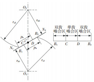 图 1 齿轮啮合关系 Figure 1 Meshing relation plot of gears
 1.2 滑动速度应用齿轮啮合理论可确定点i的滑动速度:
$ \begin{align} &\ \ \ \ \ \ \ \ \ \ \ \ \ \ \ \ \ \ \ {{v}_{i}}=\left( {{\omega }_{1}}+{{\omega }_{2}} \right)\times {{y}_{i}}, \\ &{{y}_{i}}=i{{i}^{\prime }}={{r}_{\text{b1}}}\left( \text{tan}\ {{\beta }_{1i}}-\text{tan}\ \phi \right)={{r}_{\text{b2}}}(\text{tan}\ \phi -\text{tan}\ {{\beta }_{2i}}). \\ \end{align} $
式中:rb1rb2为主从动轮的基圆半径,β1iβ2i分别为啮合点i在齿轮1和齿轮2上对应的压力角,?为啮合角.
2 Kriging预测模型上述磨损模型的工作参数、尺寸参数均是确定的,属于确定性模型.当N=1 000转,磨损次数为450时,计算时间大约为1 h,若给定另一组参数,程序需要重新计算并消耗同样的时间.在大量样本面前,直接计算的方法将不再适用,采用Kriging模型可以建立响应与模型参数的关系,当给定样本后可以快速精确地预测出磨损量(响应值).
同时,磨损是一个逐渐累积的过程,当磨损量达到极限时,齿轮失效,由齿面磨损的计算公式可以看出,在计算过程中假定了在N转内齿廓不进行更新,如果N的取值太大会造成计算精度低,因此在允许的范围内使N的取值尽可能小,但会造成计算时间长.在Kriging模型中将时间参数考虑进去,可以快速精确地预测磨损的变化趋势.
Kriging模型将模型参数看成随机变量,将磨损量看成随机响应,并将随机响应模型描述为两部分,参数化的线性回归模型和非参数化的随机过程模型.为了满足模拟过程的无偏性,可得随机响应的估计值为
$\mathit{\boldsymbol{\hat h}}\left( \mathit{\boldsymbol{x}} \right) = \mathit{\boldsymbol{f}}{\left( \mathit{\boldsymbol{x}} \right)^{\rm{T}}}{\mathit{\boldsymbol{\beta }}^ * } + \mathit{\boldsymbol{r}}{\left( \mathit{\boldsymbol{x}} \right)^{\rm{T}}}{\mathit{\boldsymbol{R}}^{ - 1}}(\mathit{\boldsymbol{H}} - \mathit{\boldsymbol{F}}{\mathit{\boldsymbol{\beta }} ^ * }). $ (4)
式中:x={x1, x2, …, xn+1}为待测点,n+1为变量数;f(x)T={f1(x), f2(x), …, fp(x)}为向量x的多项式,p为多项式数;β*={β1*, β2*, …, βp*}T为模拟的广义最小二乘估计;假设有m个样本,分别为xs1, xs2, …, xsm;r(x)={R(θk, x, xs1), R(θk, x, xs2), …, R(θk, x, xsm)}T为待测点x和样本xs1, xs2, …, xsm之间的相关向量;Rm×m为样本间的相关矩阵;H为响应样本值;F为样本的多项式;β*为模拟的最小二乘估计,
${\mathit{\boldsymbol{\beta }}^ * } = {\left( {{\mathit{\boldsymbol{F}}^{\rm{T}}}{\mathit{\boldsymbol{R}}^{ - 1}}\mathit{\boldsymbol{F}}} \right)^{ - 1}}{\mathit{\boldsymbol{F}}^{\rm{T}}}{\mathit{\boldsymbol{R}}^{ - 1}}\mathit{\boldsymbol{Y}}.$
式中:R(θk, xi, xj)是样本点中任意两个样本点xi和xj的空间相关方程,i, j∈s1, …, sm由用户自定义,其中计算效果最好,被广泛采用的是高斯相关方程.
$R({\theta _k}, {\mathit{\boldsymbol{x}}_i}, {\mathit{\boldsymbol{x}}_j}) = \prod\limits_k^{n + 1} {{\rm{exp}}( - {\theta _k}\left| {x_k^i - x_k^j} \right|{^2})} .$
由R(θk, xi, xj)可组集为相关矩阵
$\mathit{\boldsymbol{R = }}{\left[{\begin{array}{*{20}{c}}{\sigma _1^2}&{R\left( {{\mathit{\boldsymbol{x}}_1}, {\mathit{\boldsymbol{x}}_2}} \right)}& \cdots &{R\left( {{\mathit{\boldsymbol{x}}_1}, {\mathit{\boldsymbol{x}}_m}} \right)}\\{R\left( {{\mathit{\boldsymbol{x}}_2}, {\mathit{\boldsymbol{x}}_1}} \right)}&{\sigma _2^2}&{}&{}\\ \vdots &{}&{}&{}\\{R\left( {{\mathit{\boldsymbol{x}}_m}, {\mathit{\boldsymbol{x}}_1}} \right)}&{}&{}&{\sigma _m^2}\end{array}} \right]_{\left( {m \times m} \right).}}$
应用最大似然估计法可得到相关方程中θT={θ1, …, θk, …, θn+1}T的最优解θ*为
${\mathit{\boldsymbol{\theta }}^ * } = \mathop {{\rm{min}}}\limits_\theta \left\{ {{{\left| \mathit{\boldsymbol{R}} \right|}^{\frac{1}{m}}}{\sigma ^2}} \right\}.$
式中, m为样本数,|R|为相关矩阵R的行列式.
当样本给定后,可确定出β*、R、H、F的具体表达式,当给出待测点x以及f(x)的回归模型,以及r(x)的相关方程,即可通过式(4)得到
3 算例表 1为计算一对齿轮磨损需要的参数,材料为45号钢.齿轮尺寸参数、工作参数和磨损参数均参考自文献[2].虽然文献[2]只进行了理论分析,但是被大量学者认可,并在文献[12]中进行了实验验证.
表 1
mm dw2/
mm T1/
(N·m) n1/
(r·min-1) k/
(mm2·N-1)
均值 24 26 112.5 4.5 20 15.00 108 117 302 000 150 5.0e-10
最小值 - - - - 18 13.65 - - 292 940 120 3.2e-10
最大值 - - - - 22 16.35 - - 311 060 180 6.8e-10
注:z1为小齿轮齿数, z2为大齿轮齿数, aw为中心距, mn为模数, αn为齿形角, b为齿宽, dw1为小齿轮节圆直径, dw2为大齿轮节圆直径, T1为外加力矩, n1为小齿轮速度, k为磨损系数
表 1 齿轮参数 Table 1 Parameters of gear pair
定义磨损次数为150次,从第n-1次磨损到第n次磨损之间,齿轮转过了N=1 000转,并且1, 2, …, N转的任意一转中,齿轮的轮廓是恒定的,啮合点的压力和速度都相等.
由图 2和图 3可知,节点处的磨损最小,齿根处的磨损要大于齿顶的磨损,主动轮(小齿轮)的磨损大于从动轮(大齿轮)的磨损,这与参考文献[12-14]得到的结论一致.最大磨损出现在主动轮齿廓点233处和从动轮263处.如图 1所示,一对齿的啮合从B1开始至B2结束,最大磨损出现在啮入位置和啮出位置处.由图 2和图 3可知,由于考虑间隙的影响,在单双齿啮合转换处,磨损量出现先增大再减小的现象,不同于文献[2]中的一直减小的趋势.
Figure 2
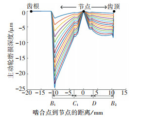 图 2 n次磨损后主动轮磨损深度(n=10, 20, ……, 150) Figure 2 Wear depth of the pinion after n wear cycles
 Figure 3
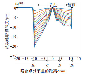 图 3 n次磨损后从动轮磨损深度(n=10, 20, ……, 150) Figure 3 Wear depth of the driven gear after n wear cycles
 若齿形角αn、齿宽b、外加力矩T1、小齿轮速度n1以及磨损系数k为变量,时间t为1 000 min,采用拉丁超立方试验设计方法,分别得到变量和真实磨损组成的样本50、100、500组,建立3种不同样本量下的Kriging近似模型(用Kriging-50,Kriging-100,Kriging-500表示).回归模型中多项式p=0,相关模型为高斯方程. 3种Kriging模型的具体参数如表 2所示.
表 2
主动轮Kriging-50模型 [0.044 2, 0.010 1, 0.074 3, 0.001 1, 0.004 6, 0.096 4] -0.487 9
主动轮Kriging-100模型 [0.022 1, 0.003 3, 0.015 6, 0.210 2, 0.000 5, 0.105 1] 0.870 2
主动轮Kriging-500模型 [1.414 2, 0.025 2, 0.040 5, 0.002 9, 0.002 1, 0.310 5] 0.173 4
从动轮Kriging-50模型 [0.031 3, 0.005 1, 0.210 2, 0.000 3, 0.000 3, 0.048 2] 0.428 3
从动轮Kriging-100模型 [0.105 1, 0.007 8, 0.009 3, 0.088 4, 0.002 3, 0.088 4] 0.498 7
从动轮Kriging-500模型 [0.250 0, 0.119 7, 0.324 2, 0.035 6, 0.048 2, 0.130 5] 0.035 3
表 2 Kriging模型中相关参数 Table 2 Parameters of the three Kriging models
图 4、5为齿轮最大磨损量变化曲线,由图 4、5可知,磨损量随时间逐渐累积增加.在样本量为50、100和500时,建立Kriging模型的时间只需几秒钟,并且模型对真实磨损量的逼近精度很高,同时,真实磨损量只提供了t0时间内的样本,Kriging模型可预测t>t0时的磨损量,并且在样本量为100组以上时,误差非常小.
Figure 4
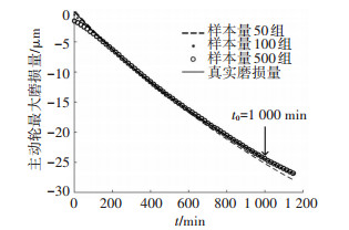 图 4 主动轮不同样本量时Kriging模型的模拟精度对比 Figure 4 Simulation precision with different Kriging model of pinion gear
 Figure 5
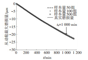 图 5 从动轮不同样本量时Kriging模型的模拟精度对比 Figure 5 Simulation precision with different Kriging model of driven gear
 为说明Kriging模型的优越性,本文同时采用人工神经网络模型(ANN)[15],建立了6-13-1形式的3层BP神经网络,隐含层的传递函数选用S型对数函数,输出层的传递函数选用purelin线性传递函数,训练函数选择trainlm函数,网络的训练误差达到10-6时结果收敛. 图 6、7为不同样本量时ANN模型的模拟精度.
Figure 6
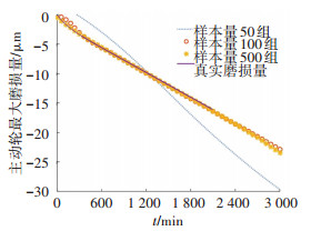 图 6 主动轮不同样本量时ANN模型的模拟精度对比 Figure 6 Simulation precision with different ANN model of pinion gear
 Figure 7
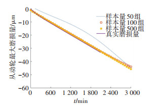 图 7 从动轮不同样本量时ANN模型的模拟精度对比 Figure 7 Simulation precision with different ANN model of driven gear
 采用50组样本训练得到的ANN模型的精确程度不高,采用100、500组的模型精确程度都很高,并且对未来趋势的预测也比较准确.同样采用50、100和500组样本建立的Kriging近似模型,3个Kriging模型的精确程度都很高,对未来趋势的预测也比较准确.由此可看出,与ANN方法相比,Kriging方法可使用更少的样本得到较高的精度.
为了检验模型的通用性,另外取50组样本分别带入上述3种Kriging模型进行检验,将样本的真实值与Kriging模型的预测值进行对比,结果表明Kriging-50模型的拟合优度为0.764 5,Kriging-100模型的拟合优度为0.998 6,Kriging-500模型的拟合优度为0.999 9,可见当采用Kriging-100模型进行检验时,拟合优度可近似达到1,因此,只需要100组样本模拟得到的Kriging模型可近似代替磨损预测模型. 图 8为采用Kriging-100模型的磨损量预测值和真实值.
Figure 8
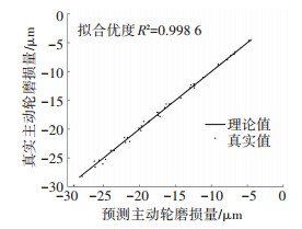 图 8 基于Kriging的预测值与真实值 Figure 8 Prediction and actual wear depth based on Kriging model
 样本量为105时,采用Kriging模型进行磨损量预测所需要的时间只有几秒钟,而用磨损仿真模型需要3.8年.可以看出,采用Kriging模型比直接采用磨损预测模型大大节约了时间和成本.
4 结论本文考虑了磨损对齿廓表面几何形状的影响,推导了几何侧隙下的齿间载荷分配公式,并以此为基础,引入Archard磨损模型和Winkler弹性力学模型,建立了低速重载齿轮的磨损量计算模型.基于Kriging方法得到了近似逼近模型,建立了齿轮参数与磨损的直接关系.为减少齿轮振动冲击提供了途径.得到的结论如下:
1) 节点处的磨损最小,齿根处的磨损要大于齿顶的磨损,主动轮(小齿轮)的磨损大于从动轮(大齿轮)的磨损.
2) 节点到齿顶的磨损分布较均匀,而齿根到节点的磨损变化较剧烈.重点应该关注齿根附近的磨损.
3) 使用很少的样本建立的Kriging模型可以完全代替磨损数值模型,计算效率和拟合优度都非常高.可用于对未知磨损的预测.
参考文献
[1] ANDERSSON S. Partial EHD theory and initial wear of gears[D]. Stockholm: Royal Institute of Technology, 1975.
[2] FLODIN A, ANDERSSON S. Simulation of mild wear in spur gears[J]. Wear, 1997, 207(1/2): 16-23. DOI:10.1016/S0043-1648(96)07467-4
[3] WU S, CHENG H S. Sliding wear calculation in spur gears[J]. Journal of Tribology, 1993, 115(3): 493-500. DOI:10.1115/1.2921665
[4] 王晓笋, 巫世晶, 周旭辉, 等. 含磨损故障的齿轮传动系统非线性动力学特性[J]. 振动与冲击, 2013, 32(16): 37-43, 69.
WANG Xiaosun, WU Shijing, ZHOU Xuhui, et al. Nonlinear dynamics analysis of gear transmission system with wear fault[J]. Journal of Vibration and Shock, 2013, 32(16): 37-43, 69. DOI:10.3969/j.issn.1000-3835.2013.16.007
[5] KUANG J H, LIN A D. The effect of tooth wear on the vibration spectrum of a spur gear pair[J]. Journal of Vibration and Acoustics, 2001, 123(3): 311-317. DOI:10.1115/1.1379371
[6] CHENG J, LI Q S. Application of the response surface methods to solve inverse reliability problems with implicit response functions[J]. Computational Mechanics, 2009, 43(4): 451-459. DOI:10.1007/s00466-008-0320-0
[7] PAPADRAKAKIS M, LAGAROS N D. Reliability-based structural optimization using neural networks and Monte Carlo simulation[J]. Computer Methods in Applied Mechanics and Engineering, 2002, 191(32): 3491-3507. DOI:10.1016/s0045-7825(02)00287-6
[8] ZHU Z F, DU X P. Reliability analysis with Monte Carlo simulation and dependent kriging predictions[J]. Journal of Mechanical Design, 2016, 138(12): 121403. DOI:10.1115/1.4034219
[9] TAN X H, BI W H, HOU X L, et al. Reliability analysis using radial basis function networks and support vector machines[J]. Computers and Geotechnics, 2011, 38(2): 178-186. DOI:10.1016/j.compgeo.2010.11.002
[10] LAURENCEAU J, SAGAUT P. Building efficient response surfaces of aerodynamic functions with kriging and cokriging[J]. Aiaa Journal, 2008, 46(2): 498-507. DOI:10.2514/1.32308
[11] LUCIFREDI A, MAZZIERI C, ROSSI M. Application of multiregressive linear models, dynamic kriging models and neural network models to predictive maintenance of hydroelectric power systems[J]. Mechanical Systems and Signal Processing, 2000, 14(3): 471-494. DOI:10.1006/mssp.1999.1257
[12] FLODIN A. Wear Investigation of Spur gear teeth[J]. Tribotest journal, 2000, 7(1): 45-60. DOI:10.1002/tt.3020070106
[13] AMARNATH M, SUJATHA C, SWARNAMANI S. Experimental studies on the effects of reduction in gear tooth stiffness and lubricant film thickness in a spur geared system[J]. Tribology International, 2009, 42(2): 340-352. DOI:10.1016/j.triboint.2008.07.008
[14] 王淑仁, 闫玉涛, 丁津原. 渐开线直齿圆柱齿轮啮合磨损试验研究[J]. 东北大学学报(自然科学版), 2004, 25(2): 146-149.
WANG Shuren, YAN Yutao, DING Jinyuan. Experimental study on mesh-wear of involute spur gears[J]. Journal of Northeastern University(Natural Science), 2004, 25(2): 146-149.
[15] 朱丽莎, 张义民, 卢昊, 等. 基于神经网络的转子振动可靠性灵敏度分析[J]. 计算机集成制造系统, 2012, 18(1): 149-155.
ZHU Lisha, ZHANG Yimin, LU Hao, et al. Reliability sensitivity analysis of rotor vibration based on neural network[J]. Computer Integrated Manufacturing Systems, 2012, 18(1): 149-155.
