 ,1, Xing-Ri Jin,11Department of Physics, College of Science,
 2Center for Quantum Sciences and School of Physics,
Received:2020-09-30Revised:2021-01-2Accepted:2021-01-9Online:2021-02-11

Abstract
Keywords:
PDF (678KB)MetadataMetricsRelated articlesExportEndNote|Ris|BibtexFavorite
Cite this article
Hang Yang, Fei Zhao, Ling-Xue Yu, De-Xiu Qiu, Cheng-Shou An, Ying-Qiao Zhang, Xing-Ri Jin. A plasmonic waveguide end-coupled to two plasmonic cavities in a non-Hermitian quantum system for dual-band unidirectional reflectionlessness. Communications in Theoretical Physics, 2021, 73(3): 035102- doi:10.1088/1572-9494/abda18
1. Introduction
Originating from the notion that non-Hermitian Hamiltonians can describe entirely real eigenvalue spectra if they keep parity-time (PT) symmetry [1, 2], the non-Hermitian optical structures with PT-symmetry have recently attracted considerable attention for studying the unusual property at exceptional points (EPs). Whereafter, a range of associated phenomena have been discovered at EPs, such as laser [3–5], optical isolation [6], non-reciprocal light propagation [7–10], coherent perfect absorption [11], power oscillation [12], electromagnetically induced transparency [13], unidirectional reflectionless phenomena [14–24], and so on.Surface plasmons (SPs) are the propagating electromagnetic waves similar to photons. Their unusual property provides the possibility to confine them to subwavelength dimensions resulting in the unique method for waveguiding below the diffraction limit. Over the past few years, a variety of investigations about the transport properties of photon or SP in non-Hermitian quantum systems based on cavities or resonators coupled to a optical waveguide [25–29] and a plasmonic waveguide (PW) [30–43] have been carried out. In non-Hermitian cavities-waveguide coupling system, Li et al analyzed the PT-symmetry-induced evolution with the geometry of three single-mode cavities coupled to a channel waveguide [28]. Rivolta et al researched the broadband unidirectional invisibility in the structure made of a waveguide and two side-coupled resonators [29]. Qiu et al investigated the dual-band unidirectional reflectionlessness and non-reciprocal entanglement by using two plasmonic cavities (PCs) side coupled to a PW [41, 42]. Wu et al compared the single-band with dual-band unidirectional reflectionlessness of SP on the premise of different number of quantum dots coupled to a PW [43]. Up to now, the majority of previous studies concentrated on the side-coupling of a waveguide to resonators or cavities. However, the case of end-coupling of resonators or cavities to a waveguide is also of practical significance in investigating the transport properties of photon or SP.
In this paper, a non-Hermitian quantum system without gain is firstly designed to analyze dual-band unidirectional reflectionlessness based on near-field coupling via two PCs end-coupled to a PW. In our scheme, only two loss PCs are used to achieve dual-band unidirectional reflectionlessness without doping any gain. So it is more high-efficiency and simplified compared with the similar schemes of unidirectional reflectionlessness [41–43].
2. Model and calculations
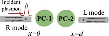
The schematics of the plasmonic structure we considered is illustrated in figure 1, which composes of a PW and two end-coupled PCs. The distance between the two PCs marked with PC-1 and PC-2 is set to d. Besides, the propagation modes of incident SP in PW are defined as R mode and L mode. Under the rotating-wave approximation, the effective non-Hermitian Hamiltonian of our composite system is given by, with ℏ = 1 [25],Figure 1.
 New window|Download| PPT slide
Figure 1.Schematic of a plasmonic structure that consists of a PW and two end-coupled PCs.
Here, vg is the group velocity of the incident SP, and ${C}_{R}^{\dagger }(x)$ (CR(x)) denotes a bosonic creation (annihilation) operator for a right-going SP at position x, while ${C}_{L}^{\dagger }(x)$ (CL(x)) describes a left-going SP. ${a}_{i}^{\dagger }$ (ai) (i = 1, 2) means creating (annihilating) an SP in the PC-i (with the frequency of ωi). The coupling strength between two PCs is denoted as g, but Vi is used to describe the coupling strength between PC-i and PW. Γi is the decay rate of PC-i. As a result, the system we studied is non-Hermitian in terms of the decay rate of PCs.
We assume that an SP enters initially from the left or right with energy Ek = vgk (k is wave vector). From the eigenvalue equation H∣ψ⟩ = Ek∣ψ⟩, the eigenstate is constructed as
3. Results and discussions
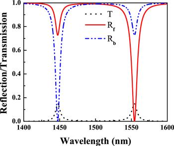
Figure 2 depicts the transmission T = ∣t∣2 (black dotted line), forward reflection Rf = ∣rf∣2 (red solid line), and backward reflection Rb = ∣rb∣2 (blue dash–dot–dot line) as the functions of wavelength. From figure 2, the forward (backward) reflections are close to 0.73 (0) and 0 (0.73) at wavelengths 1447.32 nm and 1554.36 nm, respectively. That is, dual-band unidirectional reflectionlessness appears at the wavelengths of 1447.32 and 1554.36 nm. And we use the formula Q = f/Δf to obtain the quality factor of ∼175.4 (∼188.2) for forward (backward) direction, in which the resonant frequency f is equal to 1554.36 nm (1447.32 nm) and full width half maximum Δf is equal to ∼8.86 nm (∼7.69 nm).Figure 2.
 New window|Download| PPT slide
Figure 2.Forward reflection (red solid line), backward reflection (blue dash–dot–dot line) and transmission (black dotted line) spectra as the functions of wavelength. The related parameters are η1 = η2 = η = 0.2 × 10¹³ rad s−1, Γ1 = Γ2 = 1.45η, and g = 2.98 × 10¹³ rad s−1.
Following this, the physical properties of the non-Hermitian system can be simply depicted by the scattering matrix S as
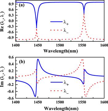
Here, our main purpose is to illuminate the corresponding physical phenomena at two EPs in the way of solving the eigenvalues of S at full length. Accordingly, the complex eigenvalues of scattering matrix S are denoted as ${\lambda }_{\pm }=t\pm \sqrt{{r}_{f}{r}_{b}}$. Based on equation (
Figure 3.
 New window|Download| PPT slide
Figure 3.The real (a) and imaginary (b) parts of the eigenvalues λ± as the functions of wavelength. Blue solid lines and red dotted lines represent eigenvalue λ+ and λ−, respectively. The related parameters are η1 = η2 = η = 0.2 × 10¹³ rad s−1, Γ1 = Γ2 = 1.45η, and g = 2.98 × 10¹³ rad s−1.
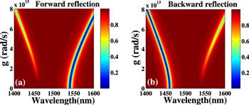
Then we discuss the influence of coupling strength g between two PCs on forward and backward reflections as shown in figure 4. Looking at the figures 4(a) and (b), the low forward reflection peak has a red-shift (figure 4(a)) and the low backward reflection peak has a blue-shift (figure 4(b)) when the coupling strength g is gradually expanded. This is because the high-energy mode and low-energy mode (two new resonance modes) have a blue-shift and a red-shift, respectively, based on plasmonic hybridization [44]. Comparing figure 4(a) with (b), we notice that the low reflection region in the forward direction in figure 4(a) corresponds to the high reflection region in the backward direction in figure 4(b), that is, the blue region corresponds to the red region, and vice versa. In this case, dual-band unidirectional reflectionlessness is achieved, and it can appear in the wide range of coupling strength g from 0 to ∼7.5 × 10¹³ rad s−1. When g exceeds ∼7.5 × 10¹³ rad s−1, the dual-band unidirectional reflectionless phenomenon disappears.
Figure 4.
 New window|Download| PPT slide
Figure 4.The forward (a) and backward reflection (b) spectra as the functions of wavelength and coupling strength g between two PCs, respectively. The related parameters are η1 = η2 = η = 0.2 × 10¹³ rad s−1, Γ1 = Γ2 = 1.45η, and g is variable.
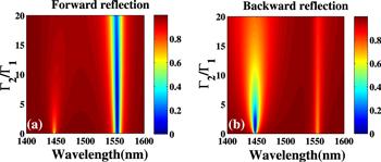
Subsequently, we focus on the dependence of forward and backward reflections on ratio Γ2/Γ1 of the decay rates of two PCs as depicted in figure 5. From figure 5(a) (figure 5(b)), there is no significant change for the position of near-zero reflection peak around wavelength 1554.36 nm (1447.32 nm) for the forward (backward) direction when the ratio Γ2/Γ1 is gradually increased. Moreover, we observe that the low reflection regions for forward and backward directions are in the wide ranges of Γ2/Γ1 from 0 to ∼16.5 and 0 to ∼4.0, respectively, as shown in figures 5(a) and (b). Comparing figure 5(a) with (b), the low forward reflection region (figure 5(a)) is corresponding to the high backward reflection region (figure 5(b)), and vise versa. These results indicate that dual-band unidirectional reflectionlessness can be controlled in the wide range of Γ2/Γ1 from 0 to ∼4.0 and single-band unidirectional reflectionlessness can appear in the wider range of Γ2/Γ1.
Figure 5.
 New window|Download| PPT slide
Figure 5.The forward (a) and backward (b) reflection spectra as the functions of wavelength and ratio Γ2/Γ1 of the decay rates of two PCs, respectively. The related parameters are η1 = η2 = η = 0.2 × 10¹³ rad s−1, Γ1 = 1.45η, g = 2.98 × 10¹³ rad s−1, and Γ2 is variable.
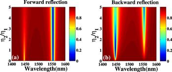
Ultimately, we discuss the effect of PC-PW coupling strengths ratio η2/η1 on forward and backward reflections. Looking at figure 6(a) (figure 6(b)), it can be found that the position of resonant peak for forward (backward) direction does not change clearly around wavelength 1554.36 nm (1447.32 nm) with increasing the ratio of η2/η1. The low reflection region for forward (backward) direction around wavelength 1554.36 nm (1447.32 nm) appears in the wide range of η2/η1 from ∼0 (∼0.3) to ∼5.0 (∼2.5). When η2/η1 exceeds ∼5.0, the forward and backward reflections are nearly the same values. At the same time, we observe that the low reflection region and the high reflection region in figures 6(a) and (b) are corresponding to each other. Consequently, in the wide range of η2/η1 from ∼0.3 to ∼2.5, we can obtain dual-band unidirectional reflectionlessness. In addition, it is worth mentioning that in the wider range of η2/η1, single-band unidirectional reflectionlessness can be realized.
Figure 6.
 New window|Download| PPT slide
Figure 6.The forward (a) and backward (b) reflection spectra as the functions of wavelength and ratio η2/η1 of PC-PW coupling strengths, respectively. The related parameters are η1 = η = 0.2 × 10¹³ rad s−1, Γ1 = Γ2 = 1.45η, g = 2.98 × 10¹³ rad s−1, and η2 is variable.
4. Conclusion
To sum up, we have investigated theoretically the dual-band unidirectional reflectionlessness at two EPs in a non-Hermitian quantum system with only one PW and two end-coupled PCs. Corresponding to the wavelengths of 1447.32 nm and 1554.36 nm, the forward (backward) reflection is ∼0.73 (∼0) and ∼0 (∼0.73), respectively. Meanwhile, the forward and backward quality factors of ∼175.4 and ∼188.2 are obtained. In addition, in the wide ranges of the coupling strength between two PCs, the ratio of decay rates of two PCs and the ratio of coupling strengths between PCs and PW, the dual-band unidirectional reflectionlessness can be achieved. Although it is difficult to realize our scheme in experiments with current technology due to the high precision requirement, our results, as theoretical support, will have the potential value for the design of plasmonic quantum devices, such as SP switching, diode-like, transistor and so on. And we believe that it can be operated experimentally in the near future.Acknowledgments
This work was supported by the National Natural Science Foundation of China (Grant Nos. 12 064 045, 11 364 044 and 11 864 043), the Science and Technology Development Foundation of Jilin Province (Grant No. 20 180 101 342JC), and Science and Technology Research Project of Education Department of Jilin Province (Grant No. JJKH20200509KJ).Reference By original order
By published year
By cited within times
By Impact factor
DOI:10.1103/PhysRevLett.80.5243 [Cited within: 1]
DOI:10.1088/0034-4885/70/6/R03 [Cited within: 1]
DOI:10.1103/PhysRevApplied.8.044020 [Cited within: 1]
DOI:10.1038/s41566-018-0213-5
DOI:10.1364/OL.40.004955 [Cited within: 1]
DOI:10.1038/nature11298 [Cited within: 1]
DOI:10.1103/PhysRevLett.103.093902 [Cited within: 1]
DOI:10.1038/nphys2927
DOI:10.1103/PhysRevLett.106.213901
[Cited within: 1]
DOI:10.1103/PhysRevLett.112.143903 [Cited within: 1]
DOI:10.1103/PhysRevLett.101.080402 [Cited within: 1]
DOI:10.1038/ncomms6082 [Cited within: 1]
DOI:10.1038/nmat3495 [Cited within: 1]
DOI:10.1364/OE.25.011778
DOI:10.1364/OE.25.024281
DOI:10.1088/2040-8986/aa9532
DOI:10.1364/OE.24.014311
DOI:10.1038/s41598-017-11376-w
DOI:10.7567/APEX.10.112001
DOI:10.1364/OE.23.029882
DOI:10.1364/OE.24.022219
DOI:10.1088/1361-6528/aaeef5 [Cited within: 1]
DOI:10.1103/PhysRevA.79.023837 [Cited within: 3]
DOI:10.1103/PhysRevA.79.023837
DOI:10.1016/j.optcom.2010.05.048
DOI:10.1103/PhysRevA.93.023814 [Cited within: 1]
DOI:10.1103/PhysRevA.94.053854 [Cited within: 2]
DOI:10.1063/1.3475769 [Cited within: 1]
DOI:10.1007/s11468-014-9846-5
DOI:10.1007/s11468-015-9944-z
DOI:10.1007/s11468-014-9845-6
DOI:10.1088/0957-4484/27/46/465703
DOI:10.1007/s11468-017-0608-z
DOI:10.1103/PhysRevA.95.053807
DOI:10.1103/PhysRevB.84.045310
DOI:10.1364/OL.37.000978
DOI:10.1038/nphys708
DOI:10.1088/1361-6455/aab5a9
DOI:10.1007/s11128-018-2139-8 [Cited within: 2]
DOI:10.1007/s11128-019-2380-9 [Cited within: 1]
DOI:10.1364/OE.26.003839 [Cited within: 3]
DOI:10.1126/science.1089171 [Cited within: 1]
