 ,2), 薛世峰, 韩丽美, 周博, 刘建林, 贾朋中国石油大学(华东), 山东青岛 266580
EXPERIMENTAL CHARACTERIZATION AND NUMERICAL SIMULATION OF DAMAGE EVOLUTION IN SEMI-CRYSTALLINE POLYMERS1)
Zhang Yi,2), Xue Shifeng, Han Limei, Zhou Bo, Liu Jianlin, Jia PengChina University of Petroleum (East China), Qingdao 266580, Shandong, China通讯作者: 2)张毅, 副教授, 主要研究方向: 高分子聚合物损伤失效机理与表征方法研究. E-mail:zhangyi@upc.edu.cn
收稿日期:2021-03-12接受日期:2021-05-13网络出版日期:2021-06-18
| 基金资助: |
Received:2021-03-12Accepted:2021-05-13Online:2021-06-18
作者简介 About authors

摘要
损伤本构模型对研究材料的断裂失效行为有重要意义, 但聚合物材料损伤演化的定量表征实验研究相对匮乏. 通过4种高密度聚乙烯(high density polythylene, HDPE)缺口圆棒试样的单轴拉伸实验获得了各类试样的载荷-位移曲线和真应力-应变曲线, 采用实验和有限元模拟相结合的方法确定了HDPE材料不同应力状态下的本构关系, 并建立了缺口半径与应力三轴度之间的关系;采用两阶段实验法定量描述了4种HDPE试样单轴拉伸过程中的弹性模量变化, 并建立了基于弹性模量衰减的损伤演化方程, 结合中断实验和扫描电子显微镜分析了应力状态对HDPE材料微观结构演化的影响. 结果表明缺口半径越小, 应力三轴度越大, 损伤起始越早、演化越快; 微观表现为: 高应力三轴度促进孔洞的萌生和发展, 但抑制纤维状结构的产生;基于实验和有限元模拟获得的断裂应变、应力三轴度、损伤演化方程等信息提出了一种适用于聚合物的损伤模型参数确定方法, 最后将本文获得的本构关系和损伤模型用于HDPE平板的冲压成形模拟, 模拟结果与实验结果吻合良好.
关键词:
Abstract
The damage constitutive model is of great significance for studying the fracture and failure behavior of materials, but very few studies have been conducted to characterize damage evolution in polymeric materials quantitatively. In this study, notched round bar specimens with four different notch radii, made from high density polyethylene (HDPE) are stretched under uniaxial tension until fracture to obtain load-displacement curves and true stress-strain curves. The constitutive equations for HDPE materials under different stress states are determined through a combination of experimental testing and finite element (FE) simulation. The FE model, which can successfully regenerate the experimentally determined load-displacement curves, is then applied to establish the relationship between notch radius and stress triaxiality. A two-stage test method is proposed to quantify the variation of elastic modulus in HDPE specimens under uniaxial tension. The damage evolution equations for four types of HDPE specimens are established based on the degradation of elastic modulus. In addition, microstructure evolution in HDPE specimens under different stress states has been analyzed using interrupted tests and scan electron microscopy (SEM). The results show that the smaller the notch radius, the higher the stress triaxiality. Additionally, damage initiates earlier and develops fasters in HDPE specimens with higher stress triaxiality. From the microstructural point of view, higher stress triaxiality facilities the initiation and evolution of cavities in HDPE specimens, while suppresses the formation of fibrillar structures. A new approach for the identification of parameters in damage evolution models has been proposed base on the information of fracture strain, stress triaxiality and damage evolution equations determined from experimental testing and FE simulation. The constitutive equation and damage evolution model determined using the proposed methods are applied to simulate the deformation and fracture behavior of HDPE plate subjected to punch loading. The simulation results are in good agreement with the punch test results.
Keywords:
PDF (25826KB)元数据多维度评价相关文章导出EndNote|Ris|Bibtex收藏本文
本文引用格式
张毅, 薛世峰, 韩丽美, 周博, 刘建林, 贾朋. 半结晶聚合物损伤演化的实验表征与数值模拟1). 力学学报, 2021, 53(6): 1671-1683 DOI:10.6052/0459-1879-21-101
Zhang Yi, Xue Shifeng, Han Limei, Zhou Bo, Liu Jianlin, Jia Peng.
引言
作为半结晶聚合物的一种, 聚乙烯(polyethylene, PE)材料因其优良的物理和力学性能、耐腐蚀性以及便捷的安装和维护过程而被广泛用于制造排水和燃气管道. 根据美国运输部管道和危险材料安全管理局的统计, 2020年美国新安装的燃气管道90%以上是由PE材料制成的, 产生了巨大的经济效益和社会效益, 同时也面临着一系列严重的安全问题. 由于材料缺陷、第三方损伤以及地壳运动等原因, PE管道的失效破坏甚至爆炸等特大事故时有发生. 因此对PE材料力学性能以及损伤失效机理的研究对PE管道的安全运行具有重要意义.聚合物材料的力学行为与应力状态紧密相关. 例如, 很多聚合物材料单轴压缩屈服应力比单轴拉伸屈服应力要大. 此外, 有研究指出应力三轴度是控制韧性损伤起始最重要的因素[1]. 因此, 自1976年以来对不同应力状态的损伤断裂行为进行了一系列的研究, 但主要是针对金属材料[2-15]. 通过改变预制缺口试样的缺口半径获得不同的应力三轴度水平, 并且缺口半径越小应力三轴度越大. 对缺口试样进行单轴拉伸实验得到的应力三轴度比较高, 通常大于1/3.有****通过对"蝴蝶状"试样进行单轴拉伸/剪切实验研究了材料在0 $\sim$ 1/3低应力三轴度状态下的力学行为[16-17]. 研究发现, 金属材料的延展性和断裂应变随着应力三轴度的增大而逐渐降低. 另一方面, 考虑应力三轴度的损伤模型逐步发展完善, 主要有两类, 一类是连续介质损伤力学模型; 另一类是基于多孔塑性理论的GTN损伤模型. Bonora等[18-20, 13]基于Lemaitre[21]和Chaboche[22]提出的连续介质损伤力学框架发展了考虑应力三轴度的连续介质损伤模型. Brünig等[6]通过有限元模拟和实验相结合的手段建立了考虑应力三轴度和洛德角的损伤准则.
近年来, 对聚合物材料在不同应力状态下的损伤断裂行为的研究也取得了一定进展[23-33]. 对聚合物材料缺口圆棒试样的单轴拉伸实验结果表明: 同等应变水平下聚合物材料的应力随着缺口半径的减小而增大[24-26, 28-29, 31, 33], 但断裂位移或断裂应变随着缺口半径的减小而减小[23-29]. Ognedal等[28]通过高速摄像机和扫描电子显微镜分别从宏观和微观角度研究了聚氯乙烯和高密度聚乙烯(high density polythylene, HDPE)材料在三轴应力状态下的体积应变和孔洞变化规律, 研究发现缺口半径越小体积应变越大、孔洞数量越多. 此外, 也有研究通过有限元模拟和实验相结合分析聚合物材料试样横截面上应力三轴度的分布[26, 28]和孔隙度的分布[26-27]. 由此可见, 文献中对聚合物材料不同应力状态下损伤行为的研究以定性分析为主, 未能定量描述聚合物材料在不同应力状态下的损伤演化过程.
因此, 本文提出一种可以定量表征聚合物材料损伤演化的两阶段实验测试方法, 结合微观结构演化分析系统地研究了应力状态对聚合物材料损伤演化的影响; 提出了适用于聚合物材料的损伤模型参数确定方法, 并将得到的损伤模型用于PE材料冲压实验的有限元模拟, 模拟结果与实验结果吻合良好, 证明了其可行性和适用性.
1 实验分析
1.1 实验材料
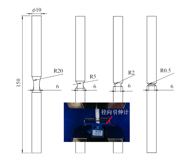
实验材料为HDPE, 其重均相对分子质量和密度分别为63 069 g/mol和0.940 g/cm$^{3}$. 为得到不同应力状态下的损伤演化方程和断裂应变, 设计了4种不同尺寸的缺口圆棒试样, 其缺口半径分别为0.5, 2, 5和20 mm, 具体试样尺寸如图1所示. 4种试样均由直径为10 mm的HDPE圆棒加工得来, 并且圆棒最小直径均为6 mm. 所有实验都通过电子万能试验机完成, 并采用径向电子引伸计测量变形过程中试样中间位置(即横截面积最小处)的直径变化(如图1中小图所示).图1
 新窗口打开|下载原图ZIP|生成PPT
图1缺口半径为20, 5, 2和0.5 mm的圆棒试样
Fig.1Example Axisymmetric specimens with notch radii of 20, 5, 2 and 0.5 mm
1.2 实验流程
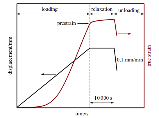
单轴拉伸实验: 以1 mm/ min的恒定速度对4种缺口圆棒试样进行单轴拉伸实验直至试样断裂, 并采用扫描电子显微镜分析断口形貌.两阶段实验: 为定量描述HDPE材料的损伤演化过程, 本文采用两阶段实验法对缺口圆棒试样进行损伤表征. 第一阶段实验为损伤引入, 其实验流程如图2所示, 首先以1 mm/min的速度将圆棒试样拉伸至不同的位移(加载阶段), 紧接着保持位移不变10 000 s (应力松弛阶段), 最后以0.1 mm/min的速度卸载(卸载阶段). 将卸载后的试样放在干燥、避光的环境保存2个月. 第二阶段实验为损伤表征, 即将第一阶段拉伸过的试样以0.01 mm/min的速度再次进行单轴拉伸实验直至试样断裂.
图2
 新窗口打开|下载原图ZIP|生成PPT
图2第一阶段实验流程示意图
Fig.2Schematic description of the test procedure used in the first stage tests
中断实验: 将采用图2实验流程拉伸到不同位移后卸载的R2和R20试样放入液氮中脆断, 应用扫描电子显微镜分析试样在变形过程中的微观结构演化规律.
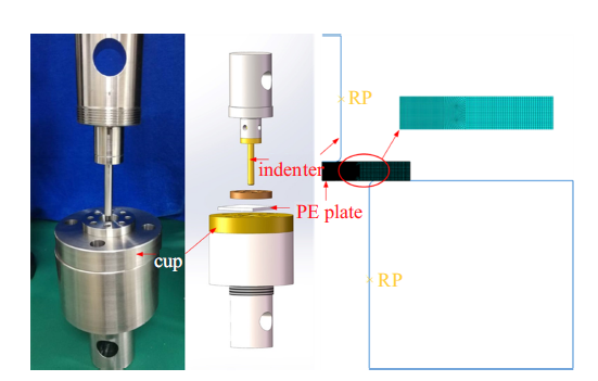
冲压实验: 采用如图3所示的冲压实验装置对40 mm$\times$40 mm$\times$3 mm的HDPE平板进行冲压实验. 压头直径分别为4, 6, 8和10 mm, 冲压速度为1 mm/min, 并记录冲压过程的载荷-位移曲线.
图3
 新窗口打开|下载原图ZIP|生成PPT
图3HDPE冲压实验有限元模型
Fig.3Finite element model for punch test on HDPE
2 有限元分析
2.1 有限元模型
缺口圆棒试样有限元模型: 对4种缺口圆棒试样的单轴拉伸实验进行有限元模拟, 以获取4种缺口圆棒试样对应的应力三轴度. 该部分工作在文献[34]中有详细介绍, 此处不再赘述.冲压实验有限元模型: 为验证本文提出损伤模型的正确性, 对HDPE平板的冲压实验进行有限元模拟分析. 考虑到试样、压头和压杯均为轴对称结构, 为减小计算量, 建立如图3所示轴对称模型. HDPE平板采用CAX8R单元, 压头和压杯采用刚体进行分析并设立参考点. 模拟过程中, 固定压杯, 压头以一定速度向下移动, 提取压头参考点的作用力和位移, 并与实验结果对比分析.
2.2 有限元本构方程
Kwon和Jar[35]提出的四段式唯象学本构模型成功用于PE材料的大变形及断裂行为的描述. 因此, 本文采用上述本构模型进行有限元分析, 具体方程为式中, $\sigma_eq $和$\varepsilon $分别为等效应力和等效应变, $\varepsilon_y $为线弹性段到非线弹性段的转折应变点, $\varepsilon_n$为颈缩起始应变点, $\varepsilon_t $为应变硬化起始应变点. 其他参数, 包括$a$, $b$, $c$, $d$, $e$, $\alpha k$, $k$, $N$, $M$, $\beta $为用户自定义参数. 本文通过迭代程序调整上述参数直至模拟结果与实验结果吻合. 方程(1a)为胡克方程, 用于描述HDPE材料线弹性力学行为[36-37]; 方程(1b)为修正Ogden方程[38], 用于描述HDPE材料非线弹性段的力学行为; 方程(1c)和(1d)为Hutchinson和Neale[39]提出的描述应变硬化行为的应力-应变方程.
3 非线性损伤模型
连续介质损伤力学采用损伤变量$D$从宏观层面描述材料的损伤演化过程. 损伤变量定义为参考体积单元中存在的不可逆缺陷(微孔洞、微裂纹等)的比率, 例如$D=0$表示无损伤的完整材料. 连续介质损伤力学的假设是当损伤变量达到临界值$D_cr$时, 材料失去承载能力[40-41], 宏观裂纹和失效破坏产生. 损伤会引起弹性模量等力学性能的衰退, 在应变等效假设下, 损伤变量可以采用下式计算式中, $E_D $和$E_{0} $分别表示有损伤和无损伤材料的弹性模量.
Borona等[18]提出金属材料韧性损伤演化过程中的损伤耗散能
式中, $D_cr $表示宏观裂纹产生时的临界损伤变量, $S_{0} $是材料参数, $n$是Ramberg-Osgood材料硬化指数, $\alpha $是决定损伤演化曲线形状的损伤指数, $p$为累积等效塑性应变. $Y$表示应变能释放率
式中, $\sigma_eq $表示等效应力, $f\left( \eta \right)$是应力三轴度$\eta (\eta ={{\sigma_{H} }/{\sigma_eq }}$, 其中$\sigma_{H} $和$\sigma_eq $分别为静水压力与等效应力)的方程, 其表达式为
式中, $\nu $为泊松比.
将式(3)中的损伤耗散能对应变能释放率求导数可得
将式(4)代入式(6)可得
根据Ramberg-Osgood幂法则[39], 等效Mises应力可以描述为累计塑性应变的函数
损伤演化的动力学规律可以描述为[5]
将式(7)和式(8)代入式(9)可得
累积等效塑性应变率$\dot{{p}}$和塑性乘子$\dot{{\lambda }}$之间的关系为
将式(11)代入式(10)可得
对式(12)进行积分可得
在单轴加载情况下, 材料破坏失效时的累计塑性应变$p_f$等于材料单轴拉伸失效时的塑性应变$\varepsilon_f $; 材料损伤起始时的累计塑性应变$p_th$等于材料单轴拉伸损伤起始时的塑性应变$\varepsilon_th $. 因此, 式(13)可以改写为
式(14)中的损伤模型将会用于HDPE材料不同应力状态下损伤演化的定量描述. 该损伤模型需要确定5个材料参数, 分别为无损伤材料的初始损伤变量$D_{0} $, 宏观裂纹产生时的临界损伤变量$D_cr $及其对应的断裂应变值, 损伤开始时对应的临界应变值$\varepsilon_th $和损伤指数$\alpha $.
4 结果和讨论
4.1 应力三轴度对损伤演化的影响
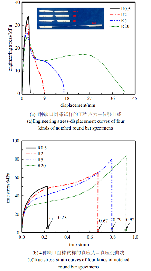
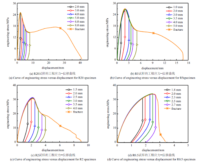
对4种缺口半径的HDPE圆棒试样进行单轴拉伸实验, 基于公式[42]式中, $\sigma_{Eng} $为工程应力, $\sigma_{T} $为真应力, $\varepsilon_{T} $为真应变. $A_{0} $和$A$分别为试样变形前和变形过程的横截面面积, 通过夹持式径向电子引伸计测得的直径计算得来. 引伸计夹具与试样接触处设计为楔形, 方便固定到R0.5和R2圆棒式样的缺口中. 对拉伸试样的数据进行处理, 可得HDPE材料的工程应力-位移和真应力-真应变曲线(如图4所示). 由于所选用的HDPE材料的应力-应变曲线重复性很好, 故图4中针对各缺口半径只列出一个试样得到的应力-位移和应力-应变曲线. 由图4可知, R20试样的工程应力-位移曲线可以分为4个阶段, 分别为弹性阶段、屈服阶段、颈缩阶段和应变硬化阶段. 但是随着曲率半径的逐渐减小, 最后的应变硬化阶段逐渐弱化直至完全消失. 此外, HDPE的屈服应力随着曲率半径的减小而增大, 但断裂位移或断裂应变随着曲率半径的减小而减小, 这与文献[23,24,25,26,27,28,29]中的结果是一致的. 由图4(a)试样拉伸断裂后的图片也可看出, 随着曲率半径减小, HDPE试样由韧性断裂转变为脆性断裂. 图4(b)的结果表明, 在真应变相同的情况下, 缺口半径更小的HDPE试样表现出更高的应力水平.
图4
 新窗口打开|下载原图ZIP|生成PPT
图4缺口圆棒试样的单轴拉伸实验结果
Fig.4Experimental results from uniaxial tensile tests on notched round bar specimens
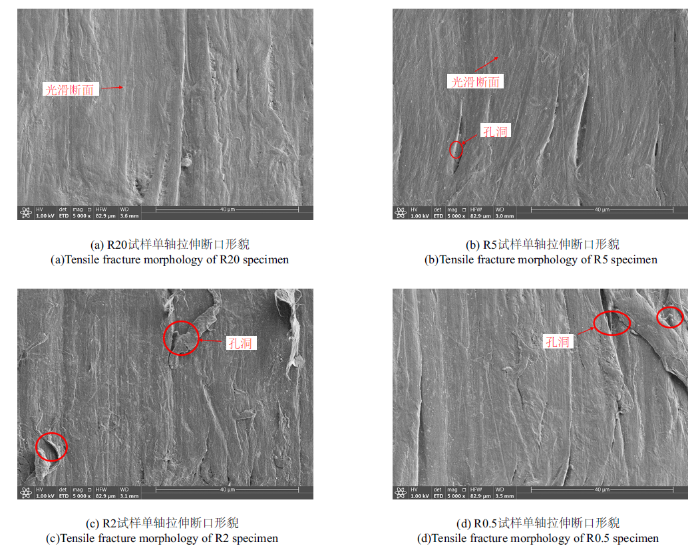
HDPE缺口圆棒试样单轴拉伸断裂后的形貌分析表明曲率半径较大的HDPE试样断裂表面有明显的韧性延展, 并伴有纤维化现象, 如图5(a)和图5(b)所示. 作为半结晶聚合物, HDPE由结晶区-非晶区-结晶区三明治分子结构组成. 在拉伸变形过程中, 相邻结晶区发生相对错动的剪切变形、结晶区自身发生旋转运动以及结晶区内分子链的解缠绕会导致分子链逐渐沿着拉伸方向取向. HDPE材料的这种局部取向包括结晶区和非晶区分子链的局部断裂、重组、取向等过程, 随着纤维的进一步拉伸, 最终导致试样的韧性断裂. 分子链局部取向引起的纤维化现象, 宏观表现为图4所示的应变硬化现象. 因纤维化现象的存在, R20和R5的HDPE试样断裂表面比较光滑, 孔洞现象不明显. 但是图5(c)和图5(d)所示的R2和R0.5试样断裂形貌表明曲率半径较小的HDPE试样孔洞化现象更加明显, 具体表现为孔洞数量增多、体积增大.
图5
 新窗口打开|下载原图ZIP|生成PPT
图5缺口圆棒试样单轴拉伸断口形貌
Fig.5Tensile fracture morphology of notched round bar specimen
图6为第一阶段实验测得的工程应力-位移曲线. 按照图2所示的实验流程将不同缺口半径的HDPE试样拉伸到不同的位移, 保持位移不变10 000 s后以恒定速度卸载试样. 需要说明的是, 图6(a) $\sim\!$图6(c)中将R20, R5和R2试样拉伸到6个不同位移后卸载, 图6(d)对应的R0.5试样只采用了5个不同位移. 这是因为R0.5试样断裂位移比较小, 故R0.5试样只测试5个不同位移.
图6
 新窗口打开|下载原图ZIP|生成PPT
图6第一阶段实验中拉伸到不同位移的缺口圆棒试样工程应力-位移曲线
Fig.6Curves of engineering stress versus displacement for notched round bar specimens with different radii stretched to various displacements in the first stage tests
为研究应力状态对HDPE材料微观结构演化的影响, 将R2和R20试样拉伸到图6所示的位移并卸载后, 放入液氮中脆断, 而后采用扫描电子显微镜研究断裂表面的形貌, 如图7和图8所示. 图7(a)为将R2试样拉伸到1.5 mm(屈服点之前)的断裂形貌, 结果表明HDPE材料屈服之前的微观结构变化比较微小, 变形主要集中于比较软的非晶区. 但是过了屈服点之后, HDPE试样中出现了明显的孔洞并且随着变形的增大孔洞逐渐增大(图7(b) $\sim\!$图7(e)). 孔洞附近伴随有不同程度的微裂纹, 或银纹现象.
图7
 新窗口打开|下载原图ZIP|生成PPT
图7单轴拉伸下R2试样的微观结构演化
Fig.7Microstructure evolution of R2 specimens subjected to uniaxial tension
图8
 新窗口打开|下载原图ZIP|生成PPT
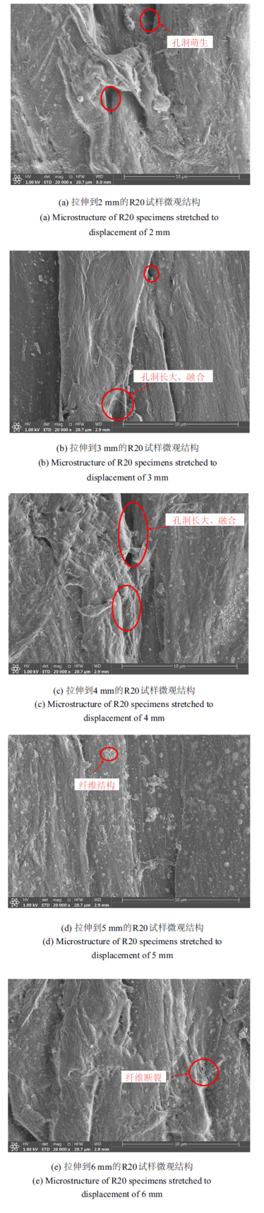
图8单轴拉伸下R20试样的微观结构演化
Fig.8Microstructure evolution of R20 specimens subjected to uniaxial tension
图8所示的R20试样的微观结构演化. 图8(a)为将R20试样拉伸到2 mm (屈服点)的断裂形貌, 结果表明R20试样在屈服点附近出现孔洞, 这与文献[40]中的实验结果是一致的. 随着变形的增大, 孔洞逐渐增大、融合(图8(b)和图8(c)). 相比于R2试样, R20试样产生明显的纤维化现象(图8(d)和图8(e)), 宏观表现为图6(a)的应变硬化现象.
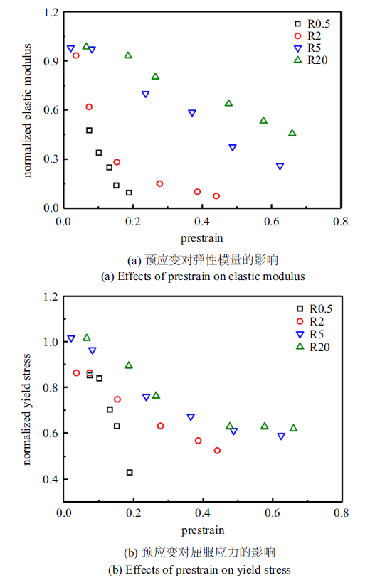
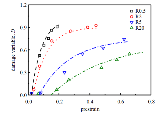
将第二阶段实验测得的HDPE试样的弹性模量和屈服应力与未进行第一阶段拉伸变形的HDPE试样的弹性模量和屈服应力进行比较, 得到归一化的弹性模量和屈服应力随第一阶段实验拉伸位移(预应变)的变化规律, 如图9所示. 结果表明HDPE材料的弹性模量和屈服应力随着预应变的增大而衰减, 而且试样缺口半径越小衰减程度越严重. 这说明第一阶段实验对HDPE材料的拉伸变形造成分子链的局部损伤, 宏观表现为力学性能的衰退. 根据式(2)和弹性模量的衰减可以计算得到不同缺口半径试样的损伤演化规律, 如图10所示. 结果表明缺口半径越小, HDPE材料的损伤萌生越早、演化越快.
图9
 新窗口打开|下载原图ZIP|生成PPT
图9第一阶段实验中引入HDPE试样的预应变对第二阶段实验测得的力学性能的影响
Fig.9Example effects of prestrain introduced in the first stage tests on mechanical properties of HDPE measured from the second tests
图10
 新窗口打开|下载原图ZIP|生成PPT
图10损伤变量随第一阶段试验施加的预应变的变化规律
Fig.10Variation of damage parameter as a function of prestrain applied in the first stage tests
4.2 损伤模型参数的确定
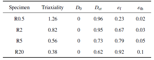
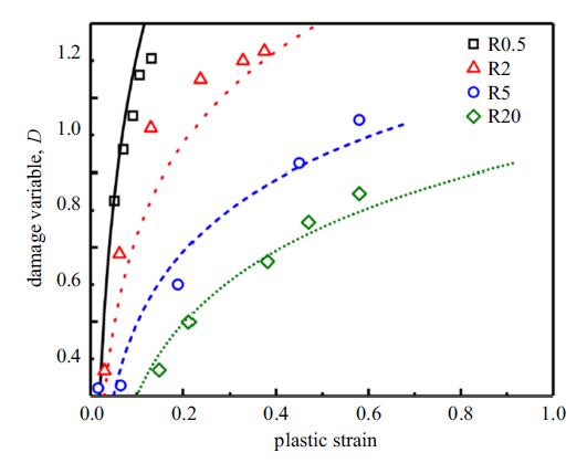
式(14)的损伤模型需要确定5个参数, 根据文献[19]中对初始损伤变量的定义, 这里取初始损伤变量$D_{0} =0$, 损伤演化指数$\alpha =1$. 其次采用$D=A\left[ {1-\exp\left( {-B\varepsilon } \right)} \right]$对图10中实验测得的损伤变量进行拟合. 采用拟合得到的曲线可以预测损伤起始时对应的应变值$\varepsilon_th $, 以及单轴拉伸实验测得的断裂应变(图4(b))对应的临界损伤变量$D_cr $. 采用式(1)本构关系和式(14)损伤模型对4种缺口圆棒试样的单轴拉伸断裂进行模拟, 获得每种试样对应的应力三轴度和损伤模型参数如表1所示. 图11为采用式(14)损伤模型预测得到的损伤演化与实验测得结果的对比, 结果表明损伤模型可以比较好地描述HDPE材料不同应力状态的损伤演化行为.Table 1
表1
表1损伤演化模型各参数的取值
Table 1
 |
新窗口打开|下载CSV
图11
 新窗口打开|下载原图ZIP|生成PPT
图11采用两阶段实验法测得的损伤演化与式(14)损伤模型对比
Fig.11Comparison of damage evolution determined from two-stage tests and predicted using model described in Eq. (14)
4.3 模拟结果与冲压实验结果对比
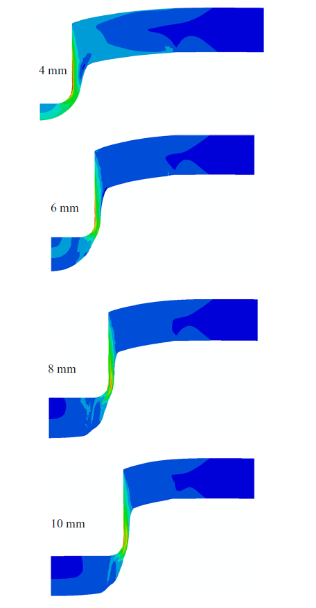
采用式(1)本构方程及表2和表3的本构方程参数和式(14)损伤演化模型及表1的损伤模型参数对压头直径为4, 6, 8和10 mm的HDPE平板冲压实验进行模拟, 结果如图12所示. 本文提出的本构损伤模型可以较好地描述HDPE平板冲压过程中的变形与损伤断裂行为, 且冲压最大载荷和断裂位移随着压头直径的增大而增大. 这是由于试样变形初期以弯曲变形为主, 压头直径越大, 载荷距边界约束条件越近, 使试样发生弯曲变形的载荷越大. 同时, 不同压头直径对试样最终的断裂形式具有显著影响(如图13), 随着压头直径的增大, 试样断裂处的厚度减薄逐渐被"颈缩"现象所代替. 这意味着随着压头直径的增大, 试样的断裂模式由脆性断裂逐渐转变为韧性断裂, 与图12实验测得的结果相吻合.Table 2
表2
表2式(1)本构方程参数的取值
Table 2
 |
新窗口打开|下载CSV
Table 3
表3
表3式(1)本构方程应变区间的取值
Table 3
 |
新窗口打开|下载CSV
图12
 新窗口打开|下载原图ZIP|生成PPT
图12有限元模拟结果与冲压实验结果对比(续)
Fig.12Comparison of the FE simulation results with punch test results (continued)
图13
 新窗口打开|下载原图ZIP|生成PPT
图13不同压头直径冲压下HDPE平板变形
Fig.13Deformation of HDPE plate under punch test with various indenter diameters
5 结论
本文采用实验和有限元模拟对HDPE材料在不同应力状态下的损伤演化的断裂行为进行了系统研究, 提出了一种适用于聚合物材料的本构关系和损伤演化模型参数的确定方法.(1)完成4种缺口圆棒试样的单轴拉伸实验, 获得了载荷-位移曲线和真应力-真应变曲线, 结果表明载荷和应力随着试样缺口半径的减小而增大, 但断裂应变随着缺口半径的减小而减小.
(2)基于缺口圆棒试样拉伸实验获得的载荷-位移曲线, 采用实验和有限元模拟相结合的方法得到HDPE材料不同应力状态的本构关系, 并获得了4种缺口圆棒试样对应的应力三轴度, 结果表明缺口半径越小的试样应力三轴度越大.
(3)通过两阶段实验法测得了HDPE材料不同应力状态下损伤变量与预应变的关系, 结合单轴拉伸实验测得的断裂应变确定了非线性损伤演化模型中的参数, 建立了HDPE材料不同应力状态的损伤演化模型.
(4)结合中断实验和扫描电子显微镜分析了HDPE材料不同应力状态下的微观结构演化, 结果表明高应力三轴度试样中的孔洞数量更多、体积更大, 但取向纤维分子结构没有低应力三轴度试样多, 宏观表现为高应力三轴度试样基本没有应变硬化阶段, 且最终为脆性断裂.
(5)基于HDPE材料的本构关系和损伤演化模型, 实现了对HDPE平板冲压过程的精确模拟, 模拟结果与实验结果有较好的一致性, 表明本文提出的确定HDPE材料本构关系和损伤模型的方法具有真实性和普适性.
参考文献 原文顺序
文献年度倒序
文中引用次数倒序
被引期刊影响因子
DOIURL [本文引用: 1]
DOIURL [本文引用: 1]
DOIURL
DOIURL
DOIURL [本文引用: 1]
DOIURL [本文引用: 1]
DOIURL
DOI

本文针对9种金属材料完成了具有不同约束程度的10类试样的延性断裂试验, 获得了发生拉、压、扭和裂尖断裂等破坏形式构型试样的载荷-位移试验关系; 基于圆棒漏斗试样拉伸试验所得直至破坏的载荷-位移曲线, 采用有限元辅助试验(finite-element-analysis aided testing, FAT)方法得到了9种材料直至破坏的全程等效应力-应变曲线, 以此作为材料本构关系通过有限元分析获得了各类试样直至临界破坏的载荷-位移关系模拟. 载荷-位移关系模拟结果与试验结果有较好的一致性, 表明用于解决试样颈缩问题的FAT方法所获得的全程材料本构关系针对各向同性材料具有真实性和普适性. 对应9种材料、10类试样的36 个载荷-位移临界断裂点, 通过有限元分析获得了对应的材料临界断裂应力、应变与临界应力三轴度, 研究表明, 第一主应力在延性变形过程中为主控断裂的主导参量; 通过研究光滑、缺口、裂纹等构型试样的断裂状态, 提出了$-1$至3范围的应力三轴度下由第一主应力主控的统一塑性临界断裂准则.
DOIURL
DOIURL
DOIURL
[本文引用: 1]
[本文引用: 1]
[本文引用: 1]
[本文引用: 1]
[本文引用: 1]
DOIURL [本文引用: 2]
DOIURL [本文引用: 1]
DOIURL [本文引用: 1]
DOIURL [本文引用: 1]
DOIURL [本文引用: 1]
DOIURL [本文引用: 3]
DOIURL [本文引用: 2]
DOIURL [本文引用: 1]
DOIURL [本文引用: 4]
DOIURL [本文引用: 2]
DOIURL [本文引用: 4]
DOIURL [本文引用: 3]
DOI
The influence of stress triaxiality and strain rate on the tensile behaviour of mineral-filled polyvinyl chloride (PVC) is investigated in this paper. Axisymmetric notched tensile specimens with notch radius equal to 20 mm, 5 mm and 2 mm were tested at three nominal strain rates of 0.0001s(-1), 0.001s(-1) and 0.01s(-1). Surface deformations were measured by digital image correlation and contour tracking, employing two orthogonal cameras, whereas infrared thermography was used to measure self-heating. The yield strength of the material was found to be strain rate and pressure dependent. The volume change was estimated from the stretch field in the notch region of the specimens and found to depend on both stress triaxiality and strain rate. A marked increase of temperature was measured at the highest strain rate.
DOI [本文引用: 1]
In this work, the yielding response of high-density polyethylene (HDPE) under different stress states and strain rates was experimentally examined and the ability of classical yield criteria to capture their deformation response assessed. A series of biaxial loading tests (pure shear, combined shear and tension/compression, pure tension/compression) using a designed Arcan testing apparatus were performed. In order to investigate a wider range of stress states, flat and cylindrical notched specimens with different curvature radii were also tested. The predictive ability of the Von Mises and the Drucker-Prager yield criteria are compared against the acquired experimental data. The Drucker-Prager yield model allowed an improved description of the available experimental results, demonstrating the need to account for pressure dependency in the yield models formulation for semi crystalline polymers. Some differences observed may be attributed to the third invariant stress tensor effects. The evolution of stress triaxiality and Lode angle parameters with equivalent plastic strain were extracted from simulations with Drucker-Prager yield criterion. The results show sensitive stress state dependency of the plastic yielding behaviour, which can be attributed to different combinations of stress triaxiality and Lode angle parameters. Also numerical simulations show that there is variation of the stress triaxiality and equivalent plastic strain along the cross section and the location of the maximum plastic strain and maximum stress triaxiality in the specimens are located at the centre of the specimens.
DOIURL [本文引用: 2]
[本文引用: 1]
DOIURL [本文引用: 1]
DOIURL [本文引用: 1]
DOIURL [本文引用: 1]
[本文引用: 1]
DOIURL [本文引用: 2]
[本文引用: 2]
DOIURL [本文引用: 1]
[本文引用: 1]
