 , 蔡力勋, 陈辉, 包陈, 刘晓坤
西南交通大学力学与工程学院,应用力学与结构安全四川省重点实验室,成都 610031
SPHERICAL INDENTATION METHOD TO DETERMINE STRESS-STRAIN RELATIONS AND TENSILE STRENGTH OF METALLIC MATERIALS1)
ZhangZhijie, CaiLixun, ChenHui, BaoChen, LiuXiaokun中图分类号:O341
文献标识码:A
版权声明:2019力学学报期刊社力学学报期刊社 所有
基金资助:
作者简介:
-->
展开
摘要
关键词:
Abstract
Keywords:
-->0
PDF (5174KB)元数据多维度评价相关文章收藏文章
本文引用格式导出EndNoteRisBibtex收藏本文-->
随着航空航天、核电工程等焊接结构、服役结构材料、新材料对小尺寸材料的力学性能测试需求日益增长,传统的大试样拉伸试验方法已难以满足需求. 源于1900年代材料硬度试验$^{ [1-2]的压入加载,Doerner$^{ [3]和Oliver[4] 基于接触理论分别于1986年和1992年提出了材料弹性模量的压入试验方法,以解决材料局部测试问题,但是该方法主要针对纳米压痕测试[5]. 1989年Hill[6]提出了球形压入的自相似理想弹塑性解. Biwa和Storakers[7], Mesarovic 等$^{ [8],Lee等[9]等先后指出了Hill解存在的局限性和不准确性.
假定延性金属材料满足连续、均匀、各向同性、Mises等效、应力-应变关系符合Hollomon律, 则材料代表性体积单元[10] (representative volume element, RVE)的应力-应变关系可表为
\begin{equation} \label{eq1} \sigma = \left\{ {\begin{array}{ll} E\varepsilon ,&\sigma \le \sigma _{ y} K\varepsilon ^n = E^n\sigma _{ y}^{1-n} \;\varepsilon ^n,&\sigma \ge \sigma _{ y} \end{array}} \right.\tag{1} \end{equation}
式中,$E$为材料弹性模量,{$\sigma $}$_{y}$为名义屈服强度,$K$为应变硬化系数,$n$为应变硬化指数.
针对符合上述幂律的延性材料,Cheng等$^{[11]基于量纲分析方法,1999年从理论上证明了单压头球压入测试获得的材料RVE应力-应变关系具有唯一性,自此球压入试验被认为具有重要的测试应用价值.目前已发展的球形压入法主要包含以下三类: (I)Haggag等[12]、Kwon等[13]、伍声宝等[14]、苏成功等[15]和金桩等[16]先后发展的基于多级压入加卸载的表征应力{$\sigma $}$_{r}$与表征应变{$\varepsilon $}$_{ r}$方法;(II)Dao等[17]、Cao等[18]、Collin等[19]和姜鹏等[20]分别提出的用于数值压入方程求解的量纲分析方法;(III)Huber等[21]、Clyne等[22]基于神经网络算法提出的压入求解方法.方法I需要多次加卸载,每次卸载得到一个应力-应变数据点,所采用的表征应力表达式({$\sigma$}$_{ r}=P_{ max}$/{A$\psi $})中约束因子{$\psi$}近似按照常数处理(Haggag方法采用{$\psi$=}2.8,Kwon方法采用{$\psi$=}3),未考虑材料类型和塑性变形程度的影响[23]. Chen等[24]考虑了材料类型的影响,采用修正的约束因子提高了压入求解的材料适应性.由于约束因子适用范围仍然有限,且较深的球压入会不同程度引发pile-up效应或sink-in效应,故方法I存在材料普适性问题且求解过程复杂.方法II依靠大量数值计算和多级拟合得到了关联载荷、深度与材料应力-应变关系参数的显式表达式,但此类表达式过度依赖有限元计算,并未从本质上理性描述材料RVE的力学行为,方程更为复杂,未见广泛应用.方法III基于神经网络算法通过海量有限元计算,将载荷-位移关系计算结果与压入试验结果通过相关性判别进行排队分析来实现材料应力-应变关系的优化求解,该方法在进行分析前需要足够的应力-应变关系与载荷-深度关系的训练样本库,往往所得"优化"分析结果因训练样本差异及载荷-深度压入曲线的准确性而产生显著敏感性.
基于能量等效假定[25 -28],即有效变形域内代表性体积单元(representative volumeelement,RVE)的vonMises等效和能量中值等效假定,本文针对球压入弹塑性问题进行半解析求解进而提出用于求解金属材料应力-应变关系和抗拉强度的试验方法,以及基于压头系数与金属压入深度的相关性假定,提出用于球压入测试的弹性模量修正模型.
1 球压入的弹性模量模型
1.1 球压入Oliver-Pharr[4 ]模型
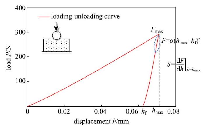
如图1所示典型的压入加卸载曲线,通过将卸载曲线初始段对深度$h$求导可得卸载刚度为\begin{equation}\label{eq2} S = \left. {\frac{\mbox{d}F}{\mbox{d}h}} \right|_{h =h_{\max } } = \alpha t(h_{\max }-h_{ f} )^{t-1}\tag{2}\end{equation}
式中,$S$为初始卸载刚度,{$\alpha$}和$t$为拟合常数,$h_{ max}$为最大压入深度,$h_{f}$为卸载后残余深度. 定义有效接触深度$h_{ c}$为
\begin{equation}\label{eq3} h_{ c} = h_{\max }-\gamma F_{\max } / S\tag{3}\end{equation}
式中,$F_{ max}$为最大压入载荷,{$\gamma$}为压头常数,{$\gamma$}=0.75,进而可求得有效接触面积$A_{ c}$为
\begin{equation}\label{eq4} A_{ c} = \pi a^2 = \pi (2Rh_{ c}-h_{ c}^2)\tag{4}\end{equation}
式中,$a$为有效接触半径,$R$为球压头半径.由赫兹接触理论得到折合模量$E_{ r}$为
\begin{equation}\label{eq5} E_{ r} = \frac{\sqrt \pi S}{2\beta \sqrt {A_{c} } }\tag{5}\end{equation}
式中,压头系数{$\beta$}为与损伤相关的参量,最终计算得出测试材料的弹性模量$E$为
\begin{equation}\label{eq6} E = ({1-v^2})\bigg/\left({\frac{1}{E_{ r} } -\frac{1-v_{ i}^2 }{E_{ i} }}\right)\tag{6}\end{equation}
式中,$v$为测试材料的泊松比,$v_{ i}$和$E_{i}$分别为球压头的泊松比和弹性模量.
 显示原图|下载原图ZIP|生成PPT
图1典型的球形压入加卸载曲线...
-->Fig. 1The schematic diagram of loading-unloading curve for spherical indentation\begin{equation}\label{eq7} \beta = e_1 \left(\frac{h}{D}\right)^2 + e_2\left(\frac{h}{D}\right) + e_3 \tag{7}\end{equation}
-->
1.2 压头系数 $\beta $模型与试验方法
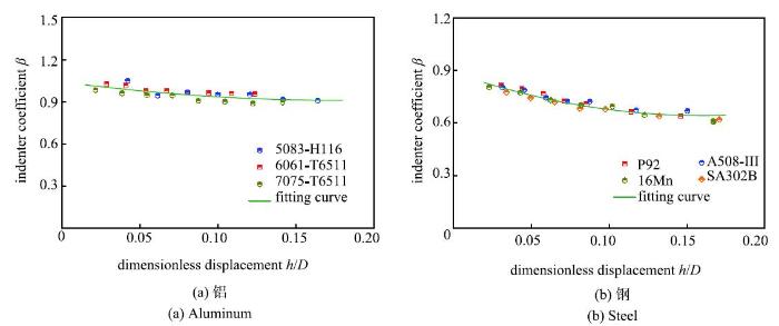
对于纳米压痕$^{ [29],试验力小,{$\beta$}一般取为定值,多数情况取为1.但是对于微米级金属材料压入,{$\beta$}是否有效、如何获得尚无文献报道.为此本文考虑压入过程中的损伤效应,提出压头系数{$\beta$}采用如下模型描述式中, $e_{1}$, $e_{2}$,$e_{3}$可通过球压头压入的多级卸载试验确定,$h$为压入深度,$D$为球压头直径.
1.3 压头系数$ \beta $模型验证
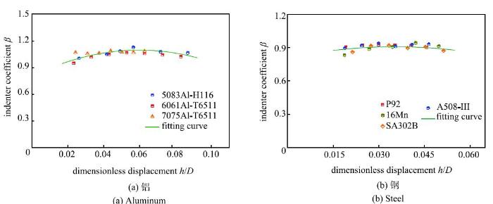
试验设备采用MMTI型压入仪(由成都微力特斯科技有限公司生产,载荷传感器量程:1500N, 位移传感器量程:2 mm,两种传感器精度都为0.5 级).选取由拉伸试验已知弹性模量的铝材:5083- H116,6061-T6511,7075-T6511;钢材:P92,16Mn, SA302B,A508-III,分别使用直径$D$=1 mm和$D$=1.5875mm的硬质钨钢球压头(压头弹性模量$E$=600GPa)对试样进行单点的多级卸载压入试验,试验曲线如图2 ~图3所示. 根据式(2)~式(6)所述方法调整各个载荷级别对应的{$\beta$}值,使得计算的弹性模量与单轴拉伸结果一致.使用式(7)拟合压头系数{$\beta$}与$h$/$D$的关系曲线确定出压头系数{$\beta$}模型的系数$e_{1}$,$e_{2}$,$e_{3}$.由于系统误差的影响,每种材料分别进行两次试验,取第二次试验数据作为有效数据,拟合结果如图4和图5所示. 拟合的模型参数如表1所示.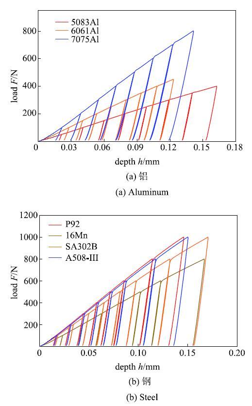 显示原图|下载原图ZIP|生成PPT
图2多级卸载试验载荷-深度曲线($D$=1 mm)...
-->Fig. 2Multi-stage unloading load-depth curves for (a) aluminum and \\(b) steel as $ D$ = 1 mm
-->
1.4 弹性模量压入测试结果验证
选取初始卸载段($h_{ max}$的95%~80%)获得初始卸载刚度$S$,并结合式(2)~式(7)以及表1中的系数求得弹性模量$E$,压入试验测得弹性模量与单轴拉伸结果对比如表2所示.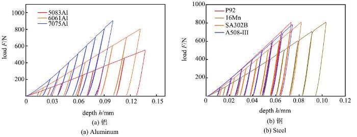 显示原图|下载原图ZIP|生成PPT
图3多级卸载试验载荷-深度曲线($D$=1.587~5 mm)...
-->Fig. 3Multi-stage unloading test load-depth curves for (a) aluminum and (b)steel as $D$=1.587~5 mm
-->
 显示原图|下载原图ZIP|生成PPT
图4压头系数{$\beta $}与$h$/$D$的关系曲线($D$=1 mm)...
-->Fig. 4The relations between indenter coefficient and $h$/$D$ for (a) aluminum and (b) steel as $D$=1 mm
-->
 显示原图|下载原图ZIP|生成PPT
图5压头系数{$\beta$}与$h$/$D$的关系曲线($D$=1.587 5mm)...
-->Fig. 5Relation curve between indenter coefficient and $h$/$D$for (a) aluminum and (b) steel as $D$=1.587 5 mm
-->
Table 1
表1
表1压头系数^0模型的参数
Table 1Parameters of indenter coefficient p model
| D/mm | E/GPa e1 | e3 | |
|---|---|---|---|
| 1 | 60 ?80 4.282 | -1.507 | 1.042 0 |
| 180 ?220 9.751 | -3.102 | 0.8870 | |
| 1.587 5 | 60 ?80 -83.13 180 ?220 -82.02 | 9.921 5.821 | 0.811 2 0.806 1 |
新窗口打开
Table 2
表2
表2不同材料弹性模量的预测
Table 2Predictions of Young’s modulus for different materials
| Materials | Young’s modulus E/GPa | Error/ | |
|---|---|---|---|
| tensile results spherical indentation | % | ||
| 5052-H24 | 68.0 | 69.3 | 1.910 |
| 5083-H116 | 70.3 | 69.8 | 0.710 |
| 6061-T6511 | 71.1 | 71.3 | 0.280 |
| 7075-T6511 | 73.4 | 71.7 | 2.320 |
| P92 | 210 | 209 | 0.142 |
| 16Mn | 195 | 194 | 0.670 |
| 16MnR | 209 | 100 | 4.360 |
| 30Cr | 197 | 199 | 1.320 |
| T91 | 195 | 202 | 3.540 |
| SA302B | 215 | 216 | 0.331 |
| A508-III | 211 | 208 | 1.470 |
新窗口打开
2 应力-应变关系球压入模型
2.1 基于能量等效假定的统一压入模型
通过建立变形域的应变能与积分中值点位置的材料RVE的应变能密度与变形域有效体积等效,以及考虑Mises等效使得复杂应力状态下RVE能量密度与单轴应力状态下RVE能量密度等效,进而建立反映连续固体的能量、载荷、位移和材料本构关系参数关系的通用模型[26- 28]. 根据积分中值定理和vonMises等效原理,整个变形域至少存在一个点M的应变能密度$u_{M}$与M点的von Mises等效应变能密度$u_{eq}$以及整个变形域的应变能密度平均值$u_{ m}$满足 等式\begin{equation}\label{eq8} u_{ m} = u_{ M} = \left. {u_{{eq}} }\right|_{_{(x_{ M} ,y_{ M} ,z_{ M} )} }\tag{8}\end{equation}
由式(1)积分可得纯弹性应变能密度和弹塑性应变能密度分别为
$$\label{eq9} u_{ e} = \int_0^{\varepsilon _{ y} } {\sigma{ d}\varepsilon } = \frac{E\varepsilon _{ y}^2 }{2}\mbox{ =}\frac{K\varepsilon _{ y}^{1 + n} }{2}\tag{9} $$
$$\label{eq10}u_{\mbox{ep}} = \int_{\varepsilon _{ y} }^{\varepsilon _{{eq}} } {\sigma { d}} \varepsilon = \int_{\varepsilon _{ y}}^{\varepsilon _{{ eq}} } {K\varepsilon ^n{ d}} \varepsilon= \frac{K}{n + 1}(\varepsilon _{_{{ eq}} }^{n + 1} -\varepsilon _{ y}^{n + 1} ) \tag{10}$$
式中,{$\varepsilon $}$_{y}$为屈服应变,{$\varepsilon $}$_{ eq}$为vonMises等效应变. 将式(9)与式(10)相加可得vonMises等效应变能 密度
\begin{equation}\label{eq11} u_{{ eq}} = u_{ e} + u_{{ ep}} = \frac{K}{n+ 1}\left(\varepsilon _{_{{ eq}} }^{n + 1}-\frac{1 -n}{2}\varepsilon _{ y}^{n + 1} \right)\tag{11}\end{equation}
由于压痕尖端存在明显的应力集中,局部材料处于高应变状态,即此时{$\varepsilon$}$_{ eq}$远大于{$\varepsilon $}$_{ y}$,相比于{$\varepsilon $}$_{ eq}^{n + 1}$,(1$-$$n)${ $\varepsilon $}$_{ y}^{n +1}$为极小量可忽略不计,由式(11)可得总应变能为
\begin{equation}\label{eq12} U = u_{ m} V = u_{{ eq}} V = \frac{K}{1 +n}V\varepsilon _{{ eq}} ^{1 + n}\tag{12}\end{equation}
式中$V$为有效变形域体积.
随着压入深度$h$增大,压痕有效变形域体积$V$与等效应变{$\varepsilon$}$_{eq}$均增大,参考Meyer律体现的载荷-深度幂律关系,可对$V$,{$\varepsilon $}$_{eq}$与$h$关系作如下幂函数假定
\begin{equation}\label{eq13} \left. {\begin{array}{l} \frac{V }{V^\ast } =k_{1 } \left(\frac{h }{h^\ast }\right)^{k_2 }\\[3mm] \varepsilon _{{ eq}} = k_3\left (\frac{h }{h^\ast }\right)^{k_4 } \\ \end{array}} \right\}\tag{13}\end{equation}
式中,$h^{\ast }$为特征长度;$V^{\ast }$为特征体积且$V^{\ast}=A^{\ast }$ $h^{\ast }$;$A^{\ast}$为特征面积;特征体积、特征面积、特征长度旨在用于实现不同球直径$D$条件下载荷-深度关系的归一化[22],可取$h^{\ast }=D$,$A^{\ast }=D^{2}$;$k_{1}$和$k_{2}$分别为有效体积系数和有效体积指数,$k_{3}$和$k_{4}$分别为有效应变系数和有效应变指数.将式(13)代入式(12)有
\begin{equation}\label{eq14} U = \frac{KD^3}{1 + n}k_1 k_3 ^{1 + n}\left(\frac{h}{D}\right)^{k_4 n + k_4 + k_2 }\tag{14}\end{equation}
2.2 压入载荷-深度关系模型
根据功能原理,外力$F$做的功$W=U$,外力为式(14)中外力功对位移的偏导结果\begin{equation}\label{eq15} F = \frac{\partial W}{\partial h} = \frac{\partia lU}{\partial h} = \frac{KD^2}{1 + n}k_1 k_3 ^{1 + n}(k_4 n + k_4 +k_2 )\left(\frac{h}{D}\right)^{k_4 n + k_4 + k_2 -1}\tag{15}\end{equation}
式中,$k_{1}$,$k_{2}$,$k_{3}$,$k_{4}$可通过少量工况的有限元分析确定,该式描述的载荷-深度关系可由如下简化方程表达\begin{equation}\label{eq16} F = Ch^{m_0 }\tag{16}\end{equation}式中,加载指数$m_{0}$和加载曲率$C$分别为
\begin{equation}\label{eq17} \left. {\begin{array}{l} m_0 { = }k_4 n + k_4 + k_2-1 \\[1mm] C = \frac{KD^{2-m_0 }k_1 k_3 ^{1 + n}(m_0 + 1)}{(1 + n)} \\ \end{array}} \right\}\tag{17}\end{equation}
2.3 求解弹塑性参数$ K$和$ n$的SSI模型
求解并化简式(17),得到弹塑性参数$K$和$n$的SSI(semi-analytical spherical indentation)模型\begin{equation}\label{eq18} \left. {\begin{array}{l} n{ = }\frac{m_0-k_4-k_2 + 1}{k_4 } \\[3mm] K = \frac{(m_0-k_2 + 1)C}{D^{2-m_0 }k_1 k_4 k_3 ^{1 + n}(m_0 + 1)} \\ \end{array}} \right\}\tag{18}\end{equation}
通过球压入试验得到载荷-深度关系后,拟合试验曲线得到加载指数$m_{0}$和加载曲率$C$,运用SSI模型可测得材料力学性能参数$K$和$n$.
2.4 SSI模型参数的确定方法
运用Ansys14.5设计如图6所示的有限元轴对称模型[30 -31],假设试样材料连续、均匀、各向同性,且遵循von Mises屈服准则.球形压头(材质为硬质碳化钨)弹性模量$E_{1}$=600GPa,泊松比$v$=0.3,压头直径$D$=1.587 5 mm,使用Contact172接触单元.被压材料满足Hollomon幂硬化模型,其弹性模量设置为$E_{2}$=70GPa和200 GPa,名义屈服强度{$\sigma $}$_{y}$分别为200$\sim $1000 MPa且间距为200MPa,应变硬化指数$n$分别为0.1~0.35且间距为0.05.试样接触面采用contact172接触单元,接触区域应力较为集中,因此网格划分较密,而远离接触区域的相对稀疏,便于减少计算成本.模拟压入最大深度为0.07mm,二维轴对称模型中压头与材料之间为线-线接触,采用Coulomb摩擦模型,摩擦系数为0.15.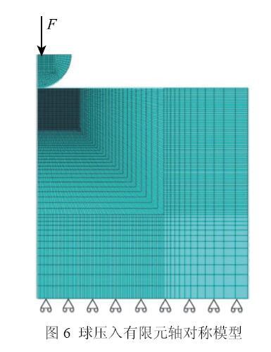 显示原图|下载原图ZIP|生成PPT
图6球压入有限元轴对称模型...
-->Fig. 6The axisymmetric FEA model under spherical indenter loading...
-->
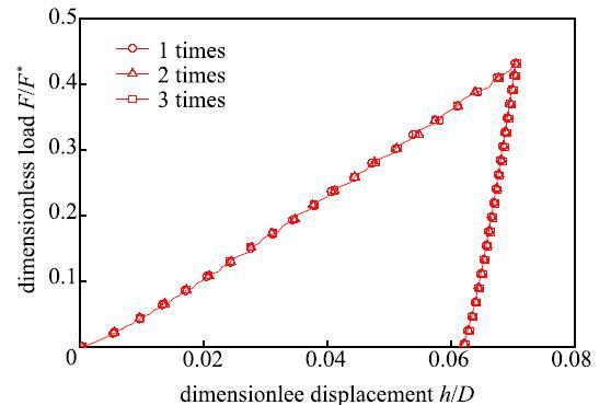
该有限元模型由32 383个节点和10 755个单元组成.为验证网格的疏密程度是否对计算结果造成影响,将网格加密进行计算.如图7所示为不同网格密度计算得到的载荷-深度曲线,结果表明使用原一
 显示原图|下载原图ZIP|生成PPT
图7网格尺寸对载荷-深度曲线的影响...倍网格密度已经满足计算要求.
-->Fig. 7Effect of grid size on load-depth curves
-->
拟合有限元轴对称模型模拟计算的载荷-深度曲线(加载段)得到加载指数$m_{0}$和加载曲率$C$,结合式(17)确定出模型参数$k_{1}$,$k_{2}$,$k_{3}$,$k_{4}$.在验证中发现,如果被预测材料的弹性模量$E$和屈服强度{$\sigma$}$_{ y}$与确定参数材料的弹性模量$E$和屈服强度{$\sigma$}$_{ y}$相差较大,则预测有较小偏差.需要根据弹性模量$E$和名义屈服强度{$\sigma $}$_{y}$对$m$进行修正,令$T$={$\sigma $}$_{y}$/$E$作为无量纲修正自变量,$m_{t}$为修正后的预测值,$m_{0}$为不修正时的预测值:
对于铝材,弹性模量$E \in $(60$\sim $80 GPa),则有
\begin{equation}\label{eq19} m_t = \frac{m_0-t_4 }{t_1 T^{t_2 }}-t_3\tag{19}\end{equation}
对于钢材,弹性模量$E \in $(180$\sim $220 GPa)则有
\begin{equation}\label{eq20} m_t = \frac{m_0 + t_4 }{t_1 T^2 + t_2 T + t_3 } -t_4\tag{20}\end{equation}
式中$t_{1}$,$t_{2}$,$t_{3}$,$t_{4}$,$t_{5}$为通过有限元确定的修正系数.
Table 3
表3
表3SSI模型统一参数
Table 3Parameters of SSI model
| Parameters | k | k | k4 | |
|---|---|---|---|---|
| Value | 6.75 | 1.60 | 0.200 | 0.500 |
| £/GPa | t1 | h | h | t4 |
| 60 ?80 | 7.900 | 0.363 | — 1.460 | 1.490 |
| 180 ?220 | 6243 | 55.00 | 0.620 0 | -1.380 |
新窗口打开
3 SSI模型验证
3.1 有限元验证
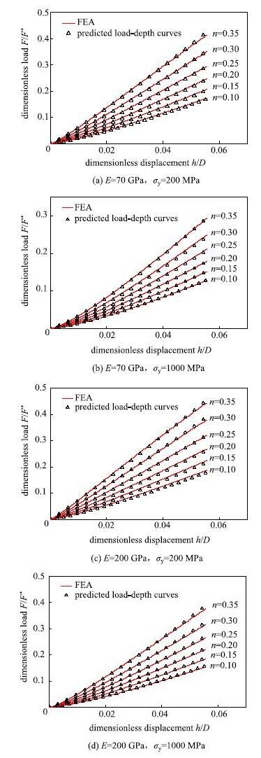
3.1.1 压入载荷-深度关系验证为实现验证的曲线与材料的本构参数$K$无关,定义无量纲化载荷$F^{\ast}$
\begin{equation}\label{eq21} F^\ast = KD^2\tag{21}\end{equation}
对于铝材使用式(17)和式(19),对于钢材则使用式(17)和式(20),可预测得到材料压入加载的载荷-深度关系曲线,将模型预测的载荷-深度关系曲线与有限元轴对称模型计算结果进行验证对比,如图8所示,可见使用压入载荷-深度关系模型预测压入载荷-深度关系效果良好.
 显示原图|下载原图ZIP|生成PPT
图8预测压入载荷-深度关系与FEA结果比较...
-->Fig. 8Comparisons of predicted load-depth curves and\\ those from FEA
-->
3.1.2 应力-应变关系验证
拟合有限元轴对称模型计算得到的载荷-深度曲线(加载段,弹性模量$E$作为已知量)得到对应的加载指数$m_{0}$和加载曲率$C$,对于铝材使用式(18)和式(19),对于钢材则使用式(18)和式(20),得到材料对应的Hollomon模型参数{$\sigma$}$_{y}$和$n$,完成对材料单轴应力-应变关系的预测.如图9所示,可见使用SSI模型预测单轴应力-应变关系效果良好.
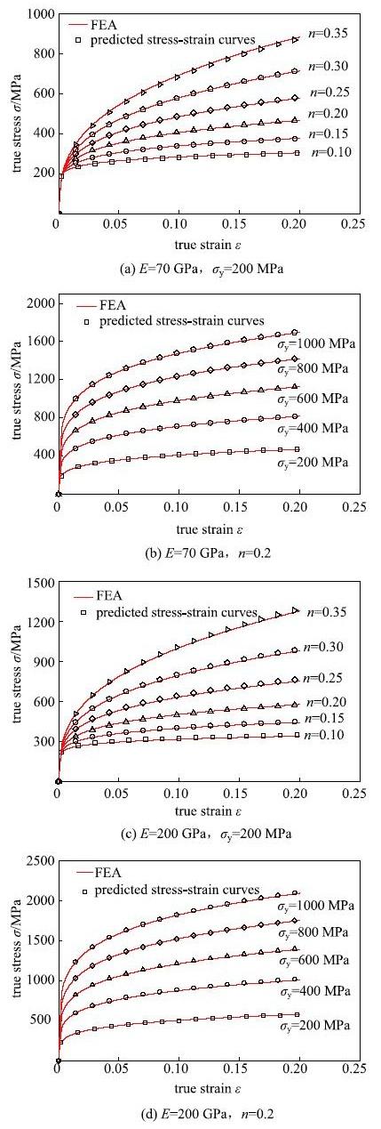 显示原图|下载原图ZIP|生成PPT
图9预测应力-应变关系与FEA结果比较...
-->Fig. 9Comparisons of predicted stress-strain curves and \\ those from FEA
-->
3.2 试验验证
3.2.1 SSI模型验证采用MMTI型压入仪,压头直径$D$=1.587 5mm的硬质钨钢球压头,试样要求表面平整光滑且光洁度$R_{a}$=0.8,厚度$B$$ \ge $2 mm. 试验相邻压点之间的距离不小于1.5mm,试验的加载速度为3 $\mu $m/s,压入深度$h$需达到70 $\mu$m以上,每种材料进行三次压入试验,由于系统误差的影响,第一次压入试验的载荷-深度曲线不作预测使用.
由于试验初始存在一段空载,需通过使用二次函数拟合初始1$\sim $5N的数据段确定出零点. 选取中间数据段,位移量$h \in $(15$\sim $70$\mu $m)的数据段,使用SSI型可对试验材料力学性能完成预测.试验测试的载荷-深度曲线如图10所示,SSI模型预测应力-应变关系曲线与单轴拉伸结果对比如图11所示.
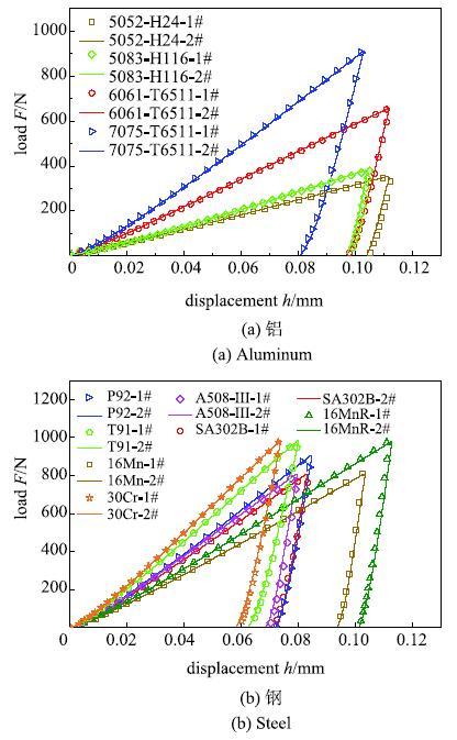 显示原图|下载原图ZIP|生成PPT
图10球压入试验载荷-深度曲线\\式中,$E_{i}$为球压头弹性模量,$E$为测试材料的弹性模量,$F$为压入载荷,$h_{p}$为塑性位移.
-->Fig. 10Load-depth curves of indentation test for \\ (a) aluminum and (b) steel
-->
 显示原图|下载原图ZIP|生成PPT
图11SSI模型测得应力-应变曲线与单轴拉伸对比...
-->Fig. 11Comparisons between predicted stress-strain curves and those from uniaxial tension for (a) aluminum and (b) steel
-->
3.2.2 与ABI球压测试方法对比验证
ABI球压测试方法[32]是根据赫兹接触理论,通过多次压入加卸载试验获得连续载荷-深度曲线(图12). 根据每次卸载段可求得一个应力-应变数据点,最终求得一系列离散的应力-应变点.
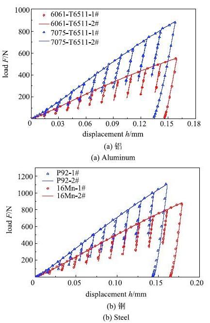 显示原图|下载原图ZIP|生成PPT
图12球压入试验载荷-深度曲线...
-->Fig. 12Load-depth curves of indentation test for \\ (a) aluminum and (b) steel
-->
真实塑性应变{$\varepsilon $}$_{p}$满足Tabor[33]表征应变表达式
\begin{equation}\label{eq22} \varepsilon _{ p} = 0.2\frac{d_{ p}}{D}\tag{22}\end{equation}
式中,$D$为球压头直径,塑性压痕直径$d_{p}$可根据赫兹接触理论计算
\begin{equation}\label{eq23} d_{ p} = \sqrt[3]{2.735FD\left(\frac{1}{E} +\frac{1}{E_{ i} }\right)\frac{h_{ p}^2 + 0.25d_{ p}^2}{h_{ p}^2 + 0.25d_{ p}^2-h_{ p} D}}\tag{23}\end{equation}
根据式(23)迭代计算得到$d_{ p}$后可计算出对应的真实应力值\begin{equation}\label{eq24} \sigma = 4F / \pi d_{ p} \delta\tag{24}\end{equation}式中,{$\delta $}为约束因子,{$\delta $}=2.87.
再将计算得到的$d_{p}$代入式(22)中求得真实塑性应变值{$\varepsilon $}$_{p}$,进一步求得真实应变{$\varepsilon $}
\begin{equation}\label{eq25} \varepsilon = \varepsilon _{ e} + \varepsilon_{ p} = \frac{\sigma }{E} + \varepsilon _{ p}\tag{25}\end{equation}
即可得到一个应力-应变数据点.多次重复上述步骤得到一系列离散的应力-应变数据点,即材料对应的单轴应力-应变关系.
试验采用MMTI型压入仪,压头为直径$D$=1mm的硬质钨钢球压头,试验材料为6061Al, 7075Al,16Mn与P92,4种延性金属材料.每次试验进行11级的等载荷间距加卸载,每种材料进行3次压入试验,由于系统误差的影响,第1次压入试验的载荷-深度曲线不作预测使用.4种材料的多级压入加卸载曲线如图12所示.
得到试验曲线后根据式(22)式(25)即可求得11个单轴应力-应变关系离散点.如图13所示,将ABI球压测试技术和SSI模型测试结果以及单轴拉伸结果进行对比.
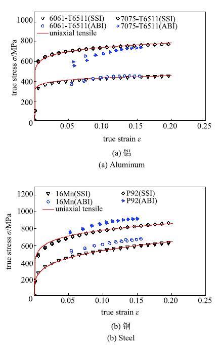 显示原图|下载原图ZIP|生成PPT
图13不同球压测试方法结果对比...
-->Fig. 13Result comparisons of different spherical indentation methods for (a) aluminum and (b) steel
-->
由图13可知,对于7075Al, 16Mn, P92,SSI模型预测的应力-应变关系相比ABI球压预测结果更接近拉伸试验结果;对于6061Al,两种球压测试方法预测结果都很接近拉伸试验结果.此外,ABI方法还存在以下不足:(1)只能得到有限的离散应力-应变数据点,无法得到连续的应力-应变关系曲线; (2)用于确定真应力的约束因子{$\delta$}与材料有关[34]; (3)式(23)中塑性压痕直径$d_{p}$的迭代收敛性难以有效 保证.
4 基于SSI模型的抗拉强度预测
使用SSI模型预测得到Hollomon模型参数$K$与$n$后,即可预测材料的工程抗拉强度$R_{m}$$^{ [35]\begin{equation}\label{eq26} R_{ m} = K\left(\frac{n}{{ e}}\right)^n\tag{26}\end{equation}式中e为自然底数.不同材料抗拉强度的预测结果如表4所示.可见球压入试验测得抗拉强度与单轴拉伸试验的相对误差大部分在3%以内,小部分在5%以内.而根据单轴拉伸试验的应力-应变关系参数,使用式(22)计算的工程抗拉强度与单轴拉伸试验结果误差也极小.这亦从侧面验证了压入试验测得的应力-应变关系与单轴拉伸试验结果具有良好的一致性.
Table 4
表4
表4不同材料抗拉强度的预测
Table 4Predictions of tensile strength for di_erent materials
| E/GPa | ^y/MPa | n | tensile results | spherical indentation | % | |
|---|---|---|---|---|---|---|
| 5052-H24 | 68.0 | 71.50 | 0.249 0 | 219.3 | 222.8 | 1.62 |
| 5083-H116 | 70.3 | 76.60 | 0.280 0 | 284 | 270.2 | 4.87 |
| 6061-T6511 | 71.1 | 351.7 | 0.071 0 | 394.4 | 387.4 | 1.79 |
| 7075-T6511 | 73.4 | 602.6 | 0.083 5 | 672.2 | 658.7 | 2.00 |
| P92 | 210 | 469.6 | 0.135 1 | 714.0 | 715.8 | 0.25 |
| 16Mn | 195 | 153.6 | 0.258 8 | 531.8 | 519.7 | 2.28 |
| 16MnR | 209 | 219.1 | 0.2146 | 553.6 | 555.8 | 0.41 |
| 30Cr | 197 | 740.0 | 0.085 1 | 886.1 | 891.5 | 0.61 |
| T91 | 195 | 625.0 | 0.1073 | 809.6 | 833.3 | 2.93 |
| SA302B | 215 | 431.2 | 0.1041 | 585.9 | 583.5 | 0.42 |
| A508-III | 211 | 376.1 | 0.165 7 | 675.5 | 672.4 | 0.46 |
新窗口打开
5 结论
(1)基于Oliver-Pharr模型,对于微米级金属材料压入,提出了压头系数{$\beta$}模型,预测弹性模量结果精准,通过大量压入结果和拉伸试验结果比对,验证了模型的有效性和准确度.(2)基于能量等效假定提出了通过球压入试验用于获取材料弹塑性应力-应变关系的SSI半解析模型,模型参数少,公式简单,预测结果精准;采用涵盖较大范围延性材料的有限元计算和针对11种金属材料的试验数据验证了模型的有效性和准确度.此外,针对4种材料,将本文所提SSI方法、ABI方法以及传统拉伸方法所测应力-应变关系进行了综合对比.结果显示,SSI球压方法预测的应力-应变曲线更接近拉伸试验结果.
(3)SSI模型方法简便、有效、实用性强;对于小尺寸结构、焊接部位以及在役设备等特种检测,该方法具有独特的优势.
The authors have declared that no competing interests exist.
参考文献 原文顺序
文献年度倒序
文中引用次数倒序
被引期刊影响因子
| [1] | . |
| [2] | |
| [3] | . |
| [4] | . |
| [5] | . . |
| [6] | . |
| [7] | . |
| [8] | . |
| [9] | . |
| [10] | |
| [11] | . |
| [12] | . |
| [13] | . |
| [14] | . . |
| [15] | . . |
| [16] | . . |
| [17] | . |
| [18] | . |
| [19] | . |
| [20] | . . |
| [21] | . |
| [22] | . |
| [23] | . |
| [24] | . |
| [25] | . |
| [26] | . |
| [27] | . |
| [28] | . . |
| [29] | |
| [30] | . . |
| [31] | . . |
| [32] | . |
| [33] | |
| [34] | . |
| [35] | . |
