楼文娟1,周为政1,张跃龙1,白航1,2,陈科技3
(1.浙江大学 建筑工程学院,杭州 310058;2.四川省建筑科学研究院,成都 610000; 3.国网浙江省电力有限公司 经济技术研究院,杭州310008)
摘要:
为降低输电线路跳线风偏带来的安全隐患,保证电力传输安全,需要准确估计其风偏动力响应。现有《电力工程高压送电线路设计手册》中的跳线风偏计算方法忽略了风荷载的脉动放大效应,以此设计的线路可能偏不安全。通过建立某高压输电线路有限元耦联模型,采用非线性有限元方法计算了直引、绕引跳线的风偏响应,并与手册计算方法进行了对比分析,指出了手册计算方法的不足。在此基础上,采用等效静力风荷载代替跳线水平风载,通过引入风荷载调整系数βc来考虑风载的脉动放大效应,对手册计算方法进行了修正。研究结果表明:手册计算方法忽略了脉动风荷载放大效应,会严重低估跳线风偏响应,与有限元仿真结果对比最大误差约37%;修正方法计算得到的跳线风偏响应与有限元结果非常接近。本文提出的修正方法可用于精细化估算跳线风偏响应。
关键词: 跳线风偏 数值模拟 手册计算方法 风荷载调整系数 修正方法
DOI:10.11918/202105117
分类号:TM726
文献标识码:A
基金项目:国家自然科学基金重点项目(51838012)
Wind-induced swing response analysis of jump line and modification of manual calculation method
LOU Wenjuan1,ZHOU Weizheng1,ZHANG Yuelong1,BAI Hang1,2,CHEN Keji3
(1.College of Civil Engineering and Architecture, Zhejiang University, Hangzhou 310058, China; 2.Sichuan Institute of Building Research, Chengdu 610000, China; 3.Economic Research Institute, State Grid Zhejiang Electric Power Co. Ltd., Hangzhou 310008, China)
Abstract:
To reduce the safety hazards caused by the wind-induced swing of transmission jump lines and to ensure the safety of power transmission, it is necessary to accurately estimate the dynamic response of the wind-induced swing. The current calculation method for wind-induced swing of jump lines in the Electric Power Engineering Design Manual of High Voltage Transmission Lineignores the pulsation amplification effect of the wind load, and the lines designed based on this method may be unsafe. A finite element coupling model of a high-voltage transmission line was established and the non-linear finite element method was used to calculate the wind-induced swing response of direct and circuitous jump lines. Meanwhile, comparison and analysis were carried out to figure out the shortcomings of the manual calculation method. On this basis, the equivalent static wind load was used to replace the horizontal wind load of the jump lines, and the wind load adjustment factor βc was introduced to give consideration to the pulsation amplification effect of the wind load for revising the calculation method of the manual. Research results show that the manual calculation method ignored the pulsation amplification effect of wind load, which would seriously underestimate the wind-induced swing response of the jump lines.The maximum error between the manual calculation method result and the finite element result was about 37%, while the wind-induced swing response of the jump line calculated by the correction method was very close to the finite element result. The correction method proposed in this paper can be used to finely estimate the wind-induced swing response of jump lines.
Key words: wind-induced swing of jump line numerical simulation manual calculation method adjustment factor of wind load correction method
楼文娟, 周为政, 张跃龙, 白航, 陈科技. 输电线路跳线风偏响应分析及手册计算方法修正[J]. 哈尔滨工业大学学报, 2021, 53(10): 79-84. DOI: 10.11918/202105117.

LOU Wenjuan, ZHOU Weizheng, ZHANG Yuelong, BAI Hang, CHEN Keji. Wind-induced swing response analysis of jump line and modification of manual calculation method[J]. Journal of Harbin Institute of Technology, 2021, 53(10): 79-84. DOI: 10.11918/202105117.

基金项目 国家自然科学基金重点项目(51838012) 作者简介 楼文娟(1963—),女,教授,博士生导师 通信作者 周为政,zwz1332913225@163.com 文章历史 收稿日期: 2021-05-24
Abstract Full text Figures/Tables PDF
输电线路跳线风偏响应分析及手册计算方法修正
楼文娟1, 周为政1

 , 张跃龙1, 白航1,2, 陈科技3
 1. 浙江大学 建筑工程学院,杭州 310058;
2. 四川省建筑科学研究院,成都 610000;
3. 国网浙江省电力有限公司 经济技术研究院,杭州 310008
收稿日期: 2021-05-24
基金项目: 国家自然科学基金重点项目(51838012)
作者简介: 楼文娟(1963—),女,教授,博士生导师
通信作者: 周为政,zwz1332913225@163.com
摘要: 为降低输电线路跳线风偏带来的安全隐患,保证电力传输安全,需要准确估计其风偏动力响应。现有《电力工程高压送电线路设计手册》中的跳线风偏计算方法忽略了风荷载的脉动放大效应,以此设计的线路可能偏不安全。通过建立某高压输电线路有限元耦联模型,采用非线性有限元方法计算了直引、绕引跳线的风偏响应,并与手册计算方法进行了对比分析,指出了手册计算方法的不足。在此基础上,采用等效静力风荷载代替跳线水平风载,通过引入风荷载调整系数βc来考虑风载的脉动放大效应,对手册计算方法进行了修正。研究结果表明:手册计算方法忽略了脉动风荷载放大效应,会严重低估跳线风偏响应,与有限元仿真结果对比最大误差约37%;修正方法计算得到的跳线风偏响应与有限元结果非常接近。本文提出的修正方法可用于精细化估算跳线风偏响应。
关键词: 跳线风偏 数值模拟 手册计算方法 风荷载调整系数 修正方法
Wind-induced swing response analysis of jump line and modification of manual calculation method
LOU Wenjuan1, ZHOU Weizheng1

 , ZHANG Yuelong1, BAI Hang1,2, CHEN Keji3
 1. College of Civil Engineering and Architecture, Zhejiang University, Hangzhou 310058, China;
2. Sichuan Institute of Building Research, Chengdu 610000, China;
3. Economic Research Institute, State Grid Zhejiang Electric Power Co. Ltd., Hangzhou 310008, China
Abstract: To reduce the safety hazards caused by the wind-induced swing of transmission jump lines and to ensure the safety of power transmission, it is necessary to accurately estimate the dynamic response of the wind-induced swing. The current calculation method for wind-induced swing of jump lines in the Electric Power Engineering Design Manual of High Voltage Transmission Line ignores the pulsation amplification effect of the wind load, and the lines designed based on this method may be unsafe. A finite element coupling model of a high-voltage transmission line was established and the non-linear finite element method was used to calculate the wind-induced swing response of direct and circuitous jump lines. Meanwhile, comparison and analysis were carried out to figure out the shortcomings of the manual calculation method. On this basis, the equivalent static wind load was used to replace the horizontal wind load of the jump lines, and the wind load adjustment factor βc was introduced to give consideration to the pulsation amplification effect of the wind load for revising the calculation method of the manual. Research results show that the manual calculation method ignored the pulsation amplification effect of wind load, which would seriously underestimate the wind-induced swing response of the jump lines.The maximum error between the manual calculation method result and the finite element result was about 37%, while the wind-induced swing response of the jump line calculated by the correction method was very close to the finite element result. The correction method proposed in this paper can be used to finely estimate the wind-induced swing response of jump lines.
Keywords: wind-induced swing of jump line numerical simulation manual calculation method adjustment factor of wind load correction method
跳线是连接耐张塔或转角塔两侧导线的引流线,跳线与导线风偏闪络一样会导致断电跳闸事故,且跳线相对于导线更为松弛,质量更轻,更容易发生大幅度风偏,危及电力系统安全。相关统计结果表明,跳线风偏闪络事故数量在近几年呈逐年增长趋势,是输电线路跳闸事故的主要原因之一[1-4]。因此,针对《电力工程高压送电线路设计手册》[5] (以下简称手册)中的跳线计算方法,指出其中的不足是有意义的。
跳线风偏响应的数值仿真方法可以得到跳线风偏的精细化结果。周超等[6]对某500 kV输电线路跳线风振响应进行分析,并与风洞试验对比,验证了有限元方法的可靠性;徐海巍等[3]用有限元方法分析了跳线风偏响应并对比了全输电线路模型、简化“2+2”模型和局部模型的计算结果,认为简化“2+2”模型能够保证计算精度并提高效率。可见有限元仿真计算体系已经能够很好地模拟输电线路跳线风偏,但是有限元方法建模困难,计算效率低,工作量大,难以大量在工程上展开。而计算手册则提供了简化的跳线风偏计算方法,更利于实际应用,但是手册方法只考虑了平均风荷载对跳线的作用,未考虑脉动风荷载的放大效应,使计算结果往往偏不安全。在2019年台风“利奇马”登陆期间,浙江某500 kV线路发生的4次跳闸事故全部为跳线风偏事故,220 kV线路发生的11次跳闸事故中有9次为跳线风偏事故。可见采用手册计算方法在部分线路地区存在一定的安全隐患,亟待改进。
本文通过将有限元仿真方法和手册计算方法进行对比分析,指出了手册计算方法的不足。并采用等效静力风荷载法的核心思想,引入风荷载调整系数βc来考虑脉动风荷载的放大效用,以此对手册方法进行修正,使手册方法能够更精细化地估算跳线风偏动力响应。
1 基于有限元方法的跳线风偏响应计算分析跳线风偏响应可以采用与计算导线风偏响应相似的有限元动态分析。与《电力工程高压送电线路设计手册》[5]给出的跳线风偏响应计算公式相比,精细的非线性有限元法引入了风场模拟结果、建立了与实际输电线路相符的有限元模型、耦合了跳线两端导线风偏的影响作用,能够得到更接近实际的分析结果。因此本文依照实际输电线路分布,按照“2+2”简化模型(即考虑转角塔左右各2档导线的计算模型)建立耦联模型,该模型在跳线风偏响应的计算上能准确替代完整的线路模型[3]。线路导线、绝缘子串参数见表 1~2。其中,等效单导线的阻力系数Cd由风洞试验得到,且Cd=0.95。
表 1
单导线 425.24 1.349 65
等效导线 1 700.96 5.396 65
注:A为导线截面积,ρ为线密度,E为弹性模量。
表 1 LGJ400/35四分裂导线及其等效单导线参数 Tab. 1 Parameters of four-bundled conductor LGJ400/35 and its equivalent conductor
表 2
56.00 0.35 67.00
表 2 XWP-240绝缘子串参数 Tab. 2 Parameters of insulator string XWP-240
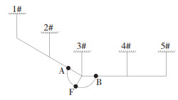
对某500 kV线路共11塔10档及耐张段之间的跳线体系进行了有限元建模,线路示意图如图 1所示,简化的“2+2”耦联模型见图 2。线路以跳线所处的3号耐张塔为界,分成两个夹角为30°19′耐张段。建模时采用等效单导线模拟实际四分裂导线[7-10],以LINK10单元模拟导线及耐张塔绝缘子串,以LINK8单元模拟悬垂绝缘子串,以MASS21单元模拟间隔棒质量。跳线由于初始应变小、找形困难、需要考虑分裂导线刚度等因素,采用BEAM188单元来模拟。由于本线路跨中垂跨比 < 0.1,故采用抛物线代替悬链线描述导线初始构型[11]。
Fig. 1
 图 1 线路示意(m) Fig. 1 Schematic diagram of the transmission line(m)
 Fig. 2
 图 2 “2+2”有限元耦联模型示意 Fig. 2 Schematic diagram of the "2+2" finite element coupling model
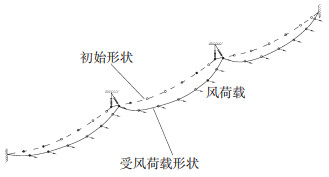
 风荷载方面,跳线和导线的多点同步风荷载采用Davenport风速谱[12],脉动风场特性,包含湍流度和湍流积分尺度、自功率谱函数、空间相关函数以及点相干函数,通过风洞试验获得。以此为基础构建山区地貌下输电线路沿线区域的脉动风速互功率谱矩阵,采用谱表示法[13]模拟山区地貌下输电线路沿线区域的三维脉动风场。时间间隔Δt取0.062 5 s,模拟时长T取2 048 s。线路处于B类地貌,基本风速U0=23.5 m/s,来流方向垂直于3#—4#线路走向。风荷载示意见图 3。
Fig. 3
 图 3 风荷载示意 Fig. 3 Schematic diagram of wind load
 跳线和导线在风荷载作用下多自由度方程为
$\boldsymbol{M} \ddot{\boldsymbol{\varDelta}}+\boldsymbol{C}_{\mathrm{S}} \dot{\boldsymbol{\varDelta}}+\boldsymbol{K}_{\mathrm{T}}(\boldsymbol{\varDelta}) \boldsymbol{\varDelta}=\boldsymbol{F}$ (1)
式中:M为结构质量矩阵,CS为结构阻尼矩阵,KT为考虑几何非线性的刚度矩阵,
$\begin{aligned}\boldsymbol{F}=& \frac{1}{2} \rho C_{\mathrm{d}} D\left(l_{1}\left(\overline{\boldsymbol{v}}_{\boldsymbol{z}, 1}+\boldsymbol{v}_{\boldsymbol{z}, 1}-\dot{\boldsymbol{\varDelta}}_{1}\right)^{2}, l_{2}\left(\overline{\boldsymbol{v}}_{\boldsymbol{z}, 2}+\boldsymbol{v}_{\boldsymbol{z}, 2}-\right.\right.\\&\left.\left.\dot{\boldsymbol{\varDelta}}_{2}\right)^{2}, \cdots, l_{n}\left(\overline{\boldsymbol{v}}_{z, n}+\boldsymbol{v}_{z, n}-\dot{\boldsymbol{\varDelta}}_{n}\right)^{2}\right)^{\mathrm{T}}\end{aligned}$ (2)
式中:ρ为空气密度,Cd、D同上文,li为第i段控制长度,vz, i为第i段z高度处平均风速,vz, i为第i段z高度处脉动风速,
有限元计算采用时域法,求解动力方程(1)采用无条件稳定的Newmark法,根据式(2)确定每个时间步的荷载项。本文分别对3#塔处跳线类型为直引跳线和绕引跳线的这两种情况进行了计算,并对计算结果进行了对比。对于这两种跳线,均以弧垂最低点F处的风偏位移来表征风偏响应,其中绕引跳线的弧垂最低点即为跳线绝缘子串夹点。跳线风偏位移方向与初始平面垂直,“2+2”耦联模型A、B、F点计算结果见表 3。
表 3
直引跳线 绕引跳线
A 平均值 0.36 0.36
均方根值 0.06 0.06
极值 0.50 0.50
B 平均值 0.39 0.39
均方根值 0.05 0.05
极值 0.50 0.50
F 平均值 2.55 1.89
均方根值 0.37 0.34
极值 3.48 2.74
表 3 直引、绕引跳线A、B、F点水平风偏位移结果 Tab. 3 Results of horizontal swing displacement of direct and circuitous jump lines at A, B and F points
2 手册计算方法手册中详细给出了直引、绕引跳线的风偏计算公式,公式忽略了跳线刚度对跳线的几何形状与风偏摆动的影响,假定跳线为柔软的抛物线或悬链线形状。
对于直引跳线,顺风向总风偏位移表示为[5]
$D_{\mathrm{H}}=D_{\mathrm{t}}+\Delta e_{\mathrm{cp}}$ (3)
式中:Dt为跳线自身水平风偏位移,可理解为跳线两端固支时的跳线风偏位移,即有限元方法中的局部模型[3];Δecp为跳线两侧悬挂点平均水平风偏位移。式(3)中Dt表示为:
$D_{\mathrm{t}}=f_{\mathrm{t}} \sin \varphi_{\mathrm{t}}$ (4)
$\varphi_{\mathrm{t}}=\tan ^{-1}\left(\frac{g_{4}}{g_{1}}\right)$ (5)
式中:ft为跳线弧垂,φt为跳线风偏角,g1为跳线单位长度重力荷载,g4为跳线单位长度风荷载。式(3)中Δecp表示为:
$\Delta e_{\mathrm{cp}}=e_{\mathrm{cp}}-e_{\mathrm{cp} 0}$ (6)
$e_{\mathrm{cp}}=\frac{1}{2}\left[\lambda_{\mathrm{A}} \cos \gamma_{\mathrm{A}} \sin \left(\frac{\psi}{2} \pm \eta_{\mathrm{A}}\right)+\lambda_{\mathrm{B}} \cos \gamma_{\mathrm{B}} \sin \left(\frac{\psi}{2} \pm \eta_{\mathrm{B}}\right)\right] $ (7)
$e_{\mathrm{cp} 0}=\frac{1}{2}\left(\lambda_{\mathrm{A}} \cos \gamma_{\mathrm{A} 0} \sin \frac{\psi}{2}+\lambda_{\mathrm{B}} \cos \gamma_{\mathrm{B} 0} \sin \frac{\psi}{2}\right) $ (8)
以A点为例:
$\gamma_{\mathrm{A}}=\tan ^{-1}\left(\frac{0.5 G_{\mathrm{V}}+W_{\mathrm{V}}}{T}\right) $ (9)
$\eta_{\mathrm{A}}=\tan ^{-1}\left(\frac{0.5 G_{\mathrm{H}}+W_{\mathrm{X}}}{T}\right)$ (10)
$G_{\mathrm{H}}=9.81 A_{1} \frac{v^{2}}{16}$ (11)
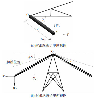
式中:ecp、ecp0分别为有、无风状态下两侧悬挂点平均水平位移;λA、λB、ηA、ηB分别为塔两侧连接导线的耐张绝缘子串长度和绝缘子串在水平面内的风偏角;γA、γA0、γB、γB0分别为有、无风状态下A、B两侧耐张绝缘子串与横担水平面间的夹角;ψ为线路转角;WV为导线重力荷载;WX为导线水平风荷载;GV为悬垂绝缘子串的自重荷载;GH为悬垂绝缘子串的水平风荷载;T为导线有风时的张力;A1为绝缘子串受风面积;v为平均风速。直引跳线风偏手册计算示意见图 4。
Fig. 4
 图 4 直引跳线风偏手册计算示意 Fig. 4 Schematic diagram of wind-induced swing calculation of direct jump line in the manual
 当杆塔有转角且加装跳线绝缘子串时,跳线为绕引跳线。手册计算绕引跳线,直接用悬垂绝缘子串的风偏角φt表示:
$\varphi_{\mathrm{t}}=\tan ^{-1}\left[\frac{T_{\mathrm{t}}\left(\cos \omega_{\mathrm{A}}+\cos \omega_{\mathrm{B}}\right)+0.5 G_{\mathrm{H}}+0.5 g_{4}\left(l_{\mathrm{HA}}+l_{\mathrm{HB}}\right)}{0.5 G_{\mathrm{H}}+0.5 g_{1}\left(l_{\mathrm{A}}+l_{\mathrm{B}}\right)+T_{\mathrm{t}}\left(\frac{h_{\mathrm{tA}}}{l_{\mathrm{A}}}+\frac{h_{\mathrm{tB}}}{l_{\mathrm{B}}}\right)}\right]$ (12)
$l_{\mathrm{HA}} \approx l_{\mathrm{A}} \sin \omega_{\mathrm{A}}$ (13)
$l_{\mathrm{HB}} \approx l_{\mathrm{B}} \sin \omega_{\mathrm{B}}$ (14)
式中:Tt为跳线有风状态下的张力;lA、lB分别为A、B侧跳线档距;ωA、ωB分别为A、B侧跳线档距与横担中线间的水平夹角;lHA、lHB分别为A、B侧跳线档距在垂直于风向方向上的投影长度;htA、htB分别为A、B两悬挂点与跳线绝缘子串线夹点之间的高差。绕引跳线风偏手册方法示意见图 5。考虑到实际工程中绕引跳线通常采用对称布置的形式,此时式(12)可简化为式(15)的形式:
$\varphi_{\mathrm{t}}=\tan ^{-1}\left(\frac{2 T_{\mathrm{t}} \cos \omega_{\mathrm{A}}+0.5 G_{\mathrm{H}}+g_{4} l_{\mathrm{HA}}}{0.5 G_{\mathrm{V}}+g_{1} l_{\mathrm{A}}+2 T_{\mathrm{t}} \frac{h_{\mathrm{tA}}}{l_{\mathrm{A}}}}\right)$ (15)
$T_{\mathrm{t}}=\sqrt{\frac{l_{\mathrm{A}}^{3} g_{6}^{2} \cos \beta}{24\left(L_{0}-l_{\mathrm{A}} / \cos \beta\right)}}$ (16)
$\beta=\tan ^{-1} \frac{h_{\mathrm{tA}}}{l_{\mathrm{A}}}$ (17)
Fig. 5
 图 5 绕引跳线风偏手册方法示意 Fig. 5 Schematic diagram of wind-induced swing calculation of circuitous jump line in the manual
 式中:L0为单侧跳线长;g6为跳线单位长度综合荷载。实际上由手册可知上式中的φt、ωA、lHA、htA等参数均与跳线风偏角φt有关,式(12)中的φt实际上是隐函数,因此在求解时通常先假定一个初始跳线风偏角φt0,然后采用迭代求解或试算的方法求解出φt。若同样以顺风向风偏位移DH来衡量绕引跳线的风偏响应,则有:
$D_{\mathrm{H}}=\lambda_{\mathrm{t}} \sin \varphi_{\mathrm{t}}$ (18)
式中λt为悬垂绝缘子串长度。
采用手册计算方法对直引、绕引跳线的顺风向风偏位移进行了计算,并与“2+2”耦联模型有限元结果进行对比,对比结果见表 4~5。
表 4
手册方法 0.33 2.38
有限元方法 均值 0.36 2.55
(min{A点,B点}) 极值 0.50 3.48
表 4 直引跳线手册方法与有限元计算结果对比 Tab. 4 Comparison between manual method results and finite element calculation results of direct jump line
表 5
手册方法 21.7 1.80
有限元方法 均值 22.9 1.90
(min{A点,B点}) 极值 34.5 2.75
表 5 绕引跳线手册方法与有限元计算结果对比 Tab. 5 Comparison between manual method results and finite element calculation results of circuitous jump line
由表 4~5可知,手册方法结果与有限元方法均值结果相差不大,最大误差为8%,但手册方法仍低估了平均风偏位移,这里认为此误差由手册方法的计算模型引起,因此称为模型误差,其对计算结果的影响较为有限。但手册计算的结果相对于有限元极值结果显著偏小,最大相差达到37%,根本原因是手册计算方法忽略了脉动风的放大效应,仅考虑平均风的影响,严重低估了跳线的风偏响应。
3 现有手册计算方法修正引入风荷载调整系数βc来考虑脉动风的放大效应,对手册计算方法中的静力风荷载进行修正,引入模型修正系数δ来使手册计算方法的结果更为准确。
采用文献[14]中基于阵风荷载包络线法(GLE)的等效静力风荷载计算方法来求解风荷载调整系数βc:
$\beta_{\mathrm{c}}=1+2 g B_{\mathrm{r}_{i}} I_{\mathrm{u}}$ (19)
$B_{\mathrm{r}_{i}}=\frac{\sqrt{\sum\limits_{j=1}^{N} \sum\limits_{k=1}^{N} \bar{\beta}_{\mathrm{r}_{i}, j} \bar{\beta}_{\mathrm{r}_{i}, k} \overline{f_{j} f_{k}}}}{\sum\limits_{j=1}^{N} \bar{\beta}_{\mathrm{r}_{i}, j} \sigma_{\mathrm{F}_{j}}}$ (20)
式中:Iu为导线或跳线有效高度处的湍流度;g为峰值因子,按中国荷载规范[15]取2.5;Bri为考虑脉动风荷载空间相关性的荷载折减系数;βri, j为导线或跳线平均风偏状态下脉动响应的影响系数,即在j节点作用单位力引起的i节点的响应;
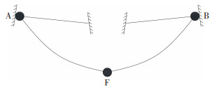
对直引跳线而言,为表示脉动风对直引跳线系统不同组成部分的影响,采用βcA、βcB和βcF来对手册方法中的静力风荷载进行放大,其中βcA以导线A点的顺风向位移为等效目标计算,βcB以导线B点的顺风向位移为等效目标计算,βcF以图 6所示的跳线局部模型中跳线弧垂最低点F处的顺风向位移为等效目标计算得到。βcA、βcB均用于式(10)中导线风荷载WX的放大,βcF用于修正式(5)中跳线单位长度风荷载g4。
Fig. 6
 图 6 跳线两端固支的局部模型 Fig. 6 Local model of jump line with fixed support at both ends
 以A侧耐张绝缘子串和F点为例,有:
$W_{\mathrm{X}, \mathrm{eq}} =\beta_{\mathrm{cA}} W_{\mathrm{X}} $ (21)
$g_{4, \mathrm{eq}} =\beta_{\mathrm{cF}} g_{4}$ (22)
式中:WX, eq和g4, eq分别为修正后的导线和跳线等效静力风荷载。以修正后的等效静力风荷载代替原静风荷载,仍以式(3)~(11)的手册计算方法可快速得到考虑一定保证率的跳线风偏位移峰值。在其余计算参数与上一节相同的条件下,直引跳线三个风荷载调整系数的取值见表 6。
表 6
1.442 1.337 1.734
表 6 直引跳线风荷载调整系数取值 Tab. 6 Values of adjustment factor of wind load of direct jump line
由表 6可知,βcA、βcB分别为1.442和1.337,与以往文献中导线的风荷载调整系数取值相近。βcF为1.734,明显大于βcA和βcB,这主要是因为跳线的跨度较小,跨度内脉动风荷载的空间相关性较强。
进一步考虑计算模型修正后的跳线风偏总位移,记为DH,若等效静力风荷载作用下的直引跳线风偏总位移为DH, eq,则DH, δ为
$D_{\mathrm{H}, \delta}=\delta D_{\mathrm{H}, \mathrm{eq}}$ (23)
直引跳线的模型修正系数δ在数值上等于表 4中有限元风偏位移均值与手册计算结果的比值,经计算为1.08。式(23)中DH, δ即为本文修正方法的计算结果。
以该修正后的直引跳线手册方法计算了图 2中直引跳线的风偏位移响应,并与有限元结果进行了对比,结果见表 7,表 7中下标eq表示该物理量是采用等效静力风荷载计算得到。可以看到,基于修正后手册方法计算的直引跳线风偏位移与有限元计算得到的风偏位移峰值非常接近,最大误差约为1.15%。
表 7
0.50 2.68 3.18 3.44 3.48 1.15
表 7 直引跳线修正方法结果 Tab. 7 Correction method results for direct jump line
该方法还可以进行进一步简化,考虑到跳线悬挂点的位移占跳线总风偏位移的比例较小,因此可用βcF代替βcA、βcB来对导线风荷载WX进行修正,此时计算过程中仅使用一个风荷载调整系数,记为βc,则上述修正方法的计算步骤将会被进一步简化。当以βc来计算图 2中直引跳线的风偏位移响应,表 7中的DH, eq和DH, δ会相应增大到3.23、3.48 m,此时修正方法的计算结果已与有限元结果高度接近。
采用同样的方法以绕引跳线绝缘子串线夹点F处的顺风向风偏位移为等效目标,采用GLE方法计算得到了用于修正绕引跳线手册计算方法的风荷载调整系数βc=1.63。计算时以βc来修正式(12)中跳线单位长度风荷载g4,此时得到的绕引跳线风偏位移即为考虑一定保证率的位移峰值。随后采用模型修正系数对该跳线风偏位移进行进一步的修正,即可得到本文修正方法的计算结果。由表 5可知绕引跳线的模型修正系数δ为1.05。
表 8给出了基于修正后的手册方法计算结果与有限元结果的对比。可以看到,基于修正后手册计算方法的绕引跳线风偏位移与有限元计算得到的风偏位移峰值相等,该方法的结果可以视为准确的,能够直接用于设计和校验。
表 8
32.7 2.62 2.75 2.75 0
表 8 绕引跳线修正方法结果 Tab. 8 Correction method results for circuitous jump line
由于修正后的手册计算方法能够快速、准确地计算直引跳线和绕引跳线的风偏角,因此该方法可视为跳线风偏响应的简化计算方法。
4 结论本文采用有限元方法基于某高压输电线路耦联模型精细化分析计算了直引跳线和绕引跳线的风偏响应;以手册方法计算了直引跳线和绕引跳线的风偏响应并分析了手册方法的误差来源;最后通过引入风荷载调整系数βc和模型修正系数δ对手册计算方法进行修正,提出了适用于工程设计和校验的简化计算方法。主要结论如下:
1) 有限元分析计算结果表明直引跳线的风偏位移在同等条件下大于绕引跳线的风偏位移,计算时应考虑跳线两端导线的耦合作用。
2) 由于未考虑脉动风的放大作用和客观存在的模型误差,现行手册计算方法得到的跳线风偏位移要明显小于有限元计算结果,最大相差37%。
3) 基于GLE等效静力风荷载理论得到的直引跳线和绕引跳线的风荷载调整系数分别为1.73和1.63,采用修正后的手册方法得到的跳线风偏响应与有限元计算的风偏响应峰值非常接近,可以满足设计和校验的需要。
参考文献
[1] 龚坚刚. 浙江电网跳线风偏跳闸的分析与措施[J]. 华东电力, 2007, 35(5): 112.
GONG Jiangang. Line trips in Zhejiang Power Grid due to windage yaw of jumper wires and relevant countermeasures[J]. East China Electric Power, 2007, 35(5): 112. DOI:10.3969/j.issn.1001-9529.2007.05.032
[2] 朱映洁, 林方新. 跳线风偏闪络原因分析及预防措施研究[J]. 南方能源建设, 2016, 3(2): 77.
ZHU Yingjie, LIN Fangxin. Research on flashover factors of jumper wires caused by windage yaw and its preventive measures[J]. Southern Energy Construction, 2016, 3(2): 77. DOI:10.16516/j.gedi.issn2095-8676.2016.02.015
[3] 徐海巍, 楼文娟, 李天昊, 等. 微地形下输电线路跳线的风偏分析[J]. 浙江大学学报(工学版), 2017, 51(2): 264.
XU Haiwei, LOU Wenjuan, LI Tianhao, et al. Wind-induced swing investigation on transmission line jumper wire under hilly terrain[J]. Journal of Zhejiang University(Engineering Science), 2017, 51(2): 264. DOI:10.3785/j.issn.1008-973X.2017.02.006
[4] 王柯. 耐张塔边相跳线和风偏闪络分析研究[J]. 贵州电力技术, 2017, 20(7): 6.
WANG Ke. Analysis and research of the side-phase jumper wires and windage yaw flashover of strain tower[J]. Power Systems and Big Data, 2017, 20(7): 6.
[5] 张殿生. 电力工程高压送电线路设计手册[M]. 2版. 北京: 中国电力出版社, 2002: 108.
ZHANG Diansheng. Electric power engineering design manual of high voltage transmission line[M]. 2nd ed. Beijing: China Electric Power Press, 2002: 108.
[6] 周超, 王阳, 芮晓明. 500 kV输电线路跳线风偏有限元分析与试验研究[J]. 工程设计学报, 2020, 27(6): 713.
ZHOU Chao, WANG Yang, RUI Xiaoming. Finite element analysis and experimental study on wind-induced swing of 500 kV transmission line jumper wire[J]. Chinese Journal of Engineering Design, 2020, 27(6): 713. DOI:10.3785/j.issn.1006-754X.2020.00.084
[7] 李天昊. 输电导线气动力特性及风偏计算研究[D]. 杭州: 浙江大学, 2016
LI Tianhao. Study on aerodynamic characteristics and wind-induced swing of transmission lines[D]. Hangzhou: Zhejiang University, 2016
[8] 楼文娟, 吴登国, 苏杰, 等. 超高压输电线路风偏闪络及导线风荷载取值讨论[J]. 高电压技术, 2019, 45(4): 1252.
LOU Wenjuan, WU Dengguo, SU Jie, et al. Discussion on wind-induced swing flashover and conductor wind load of EHV transmission lines[J]. High Voltage Engineering, 2019, 45(4): 1252. DOI:10.13336/j.1003-6520.hve.20190329022
[9] 吕中宾, 白航, 杨晓辉, 等. 某交流特高压线路风偏分析[J]. 高压电器, 2019, 55(1): 173.
Lü Zhongbin, BAI Hang, YANG Xiaohui, et al. Analysis of one UHVAC transmission line windage yaw[J]. High Voltage Apparatus, 2019, 55(1): 173. DOI:10.13296/j.1001-1609.hva.2019.01.026
[10] 楼文娟, 白航, 杨晓辉, 等. 特高压输电线路动态风偏响应及参数影响分析[J]. 土木工程学报, 2019, 52(3): 41.
LOU Wenjuan, BAI Hang, YANG Xiaohui, et al. Dynamic wind-induced swing response and parameters' influence analysis of UHV transmission lines[J]. China Civil Engineering Journal, 2019, 52(3): 41.
[11] 刘萌萌. 山地风场下输电线路风致响应研究[D]. 杭州: 浙江大学, 2017
LIU Mengmeng. Research of wind-induced response of transmission line under mountain wind field[D]. Hangzhou: Zhejiang University, 2017
[12] DAVENPORT A G. The relationship of wind structure to wind loading[C]//Proceedings of Symposium on Wind Effect on Building and Structures. London: National Physics Laboratory, 1965: 54
[13] SHINOZUKA M, JAN C M. Digital simulation of random processes and its applications[J]. Journal of Sound and Vibration, 1972, 25(1): 111. DOI:10.1016/0022-460X(72)90600-1
[14] 罗罡. 输电导线风偏精细化分析和等效静力风荷载研究[D]. 杭州: 浙江大学, 2017
LUO Gang. Refined analysis of wind-induced conductor swing and research of equivalent static wind loads on transmission lines[D]. Hangzhou: Zhejiang University, 2017
[15] 建筑结构荷载规范: GB 50009—2012[S]. 北京: 中国建筑工业出版社, 2012
Load code for the design of building structures: GB 50009—2012[S]. Beijing: China Construction Industry Press, 2012
