Author NameAffiliation
Yanwei Huang College of Electrical Engineering and Automation, Fuzhou University, Fuzhou 350116, China
Yuqing Xie College of Electrical Engineering and Automation, Fuzhou University, Fuzhou 350116, China
Wenchao Huang College of Electrical Engineering and Automation, Fuzhou University, Fuzhou 350116, China
Abstract:
A simple method is proposed to optimize the thickness parameter of the boundary layer of the saturation function in the Complementary Sliding Mode Control (CSMC). A pair of complementary sliding surfaces are constructed. And the Taylor series is used to estimate the steady-state error of CSMC system to optimize the parameter value for the boundary layer of the saturation function without artificial settings. This proposed CSMC strategy is applied to the speed regulation in permanent magnet synchronous motor with lump uncertainties. The experimental results show that the proposed CSMC strategy can obtain an optimal value for the boundary layer parameter, effectively suppressing the chattering, and keep an excellent system performance.
Key words: CSMC saturation function boundary layer parameter Taylor series speed regulation
DOI:10.11916/j.issn.1005-9113.17150
Clc Number:TP272
Fund:
Yanwei Huang, Yuqing Xie, Wenchao Huang. Complementary Sliding Mode Speed Control with Saturation Function Boundary Layer Optimization[J]. Journal of Harbin Institute of Technology (New Series), 2019, 26(5): 67-71. DOI: 10.11916/j.issn.1005-9113.17150

Fund Sponsored by the National Natural Science Foundation of China(Grant No.61174051), the Natural Science Foundation of Fujian Province(Grant No.2017J05101) and the Technology Project of Fujian Province(Grant No.2019H0007) Corresponding author Wenchao Huang, E-mail: sjtu_huanghao@fzu.edu.cn Article history Received: 2017-12-02
Contents Abstract Full text Figures/Tables PDF
Complementary Sliding Mode Speed Control with Saturation Function Boundary Layer Optimization
Yanwei Huang, Yuqing Xie, Wenchao Huang


College of Electrical Engineering and Automation, Fuzhou University, Fuzhou 350116, China
Received: 2017-12-02
Sponsored by the National Natural Science Foundation of China(Grant No.61174051), the Natural Science Foundation of Fujian Province(Grant No.2017J05101) and the Technology Project of Fujian Province(Grant No.2019H0007)
Corresponding author: Wenchao Huang, E-mail: sjtu_huanghao@fzu.edu.cn.
Abstract: A simple method is proposed to optimize the thickness parameter of the boundary layer of the saturation function in the Complementary Sliding Mode Control (CSMC). A pair of complementary sliding surfaces are constructed. And the Taylor series is used to estimate the steady-state error of CSMC system to optimize the parameter value for the boundary layer of the saturation function without artificial settings. This proposed CSMC strategy is applied to the speed regulation in permanent magnet synchronous motor with lump uncertainties. The experimental results show that the proposed CSMC strategy can obtain an optimal value for the boundary layer parameter, effectively suppressing the chattering, and keep an excellent system performance.
Keywords: CSMC saturation function boundary layer parameter Taylor series speed regulation
1 Introduction Complementary Sliding Mode Control (CSMC) by designing a pair of mutually compensating sliding surfaces to modify the Sliding Mode Control (SMC), the phase trajectory converges to the equilibrium point along the intersection of the pair of sliding surfaces[1]. Compared with SMC, the steady-state error is reduced by a half[2-3]. However, the control law of CSMC is still using the sign function to ensure the system robustness, it is inevitable to result in the high frequency chattering. The use of the saturation function to replace the sign function is an effective method to weaken the chattering, and the control precision of the system is also be ensured[4-6]. However, the introduction of the saturation function adds a boundary layer parameter, which needs artificial settings[7]. The boundary layer parameter being too large will reduce the system steady state accuracy while being too small will aggravate the chattering[8]. Therefore, the boundary layer parameter setting is very important to ensure the performance of CSMC system[9]. A fuzzy function is used to design an approximate saturation function for SMC to regulate the speed of the induction motor. The optimization of the boundary layer parameter can be adjusted by the fuzzy rules according to the uncertainty of the system [10]. A modification of the SMC is proposed to improve the speed accuracy with the saturation function boundary layer parameter designed by fuzzy rules[11]. The nonlinear control design tool of MATLAB toolbox is used to optimize the boundary layer parameter of the saturation function of SMC, and the direct thrust control of linear motor is implemented[12]. In this method, the four parameters: switching gain, sliding mode surface coefficient, convergence law coefficient and boundary layer parameters, are optimized simultaneously. However, this algorithm has too high computational complexity.
In the CSMC system, the joint action saturation function and its switching gain suppresses the high frequency chattering[13-15]. Here, an optimization method of boundary layer parameter of the saturation function is proposed for CSMC strategy. Firstly, the complementary sliding surfaces are constructed by generalized and complementary sliding surfaces. Then the relationship between the boundary layer parameter and the switching gain is obtained by using the Taylor series to expand speed error. The boundary layer parameter optimization is solved for the saturation function. Moreover, the CSMC speed regulation is applied in the Permanent Magnet Synchronous Motor (PMSM) platform. Experiments show that the CSMC strategy with the optimization of the saturation function boundary layer does not require artificial settings and the optimal speed performance can be obtained at the same time.
2 CSMC Control System 2.1 PMSM Mathematical Model Ignoring the effect of magnetic saturation, harmonic back electromotive force, hysteresis and eddy current loss, the mathematical model of the mechanical motion of the surface-type PMSM in the d-q-o synchronous rotating coordinate system is,
$J\dot w + Bw = {T_e} - {T_L} = {K_f}{i_q} - {T_L}$ (1)
where w is the rotor mechanical angular speed, J is the moment inertia, B is the viscous damping coefficient, Te is the motor electromagnetic torque, TL is the load torque, Kf is the electromagnetic torque coefficient, iq is the q-phase current in the d-q-o coordinate system.
In consideration of the parameters perturbation, friction coefficient and other uncertain factors, Eq.(1) can be described as,
$\dot w = {A_n}w + {B_n}{i_{\rm{q}}} + H$ (2)
where An=-Bo/Jo, Bn=Kfo/Jo, lump uncertainty H=
2.2 CSMC Speed Regulation CSMC is applied to a speed control for PMSM, the definition of tracking error e is,
$\mathit{\boldsymbol{e}} = {\mathit{\boldsymbol{w}}^*} - \mathit{\boldsymbol{w}}$ (3)
where w* is the given rotor angular speed.
The generalized sliding surface Sg is defined as[1],
${S_{\rm{g}}} = \left( {\frac{{\rm{d}}}{{{\rm{d}}t}} + \lambda } \right)\int_0^t {e\left( \tau \right){\rm{d}}\tau } $ (4)
where the coefficient λ>0.
Derivative of Eq.(4) is,
${{\dot S}_{\rm{g}}} = \dot e + \lambda e = {{\dot w}^*} - {A_n}w - {B_n}{i_{\rm{q}}} - H + \lambda e$ (5)
The complementary sliding surface Sc is,
${S_{\rm{c}}} = \left( {\frac{{\rm{d}}}{{{\rm{d}}t}} - \lambda } \right)\int_0^t {e\left( \tau \right){\rm{d}}\tau } $ (6)
The relationship between these two sliding surfaces is[1],
${{\dot S}_{\rm{g}}} = \lambda \left( {{S_{\rm{g}}} + {S_{\rm{c}}}} \right) + {{\dot S}_{\rm{c}}}$ (7)
According to Eq.(2) of the system, the tracking error converges to the boundary layer within a finite time. The robust control law of CSMC is designed as,
$i_{\rm{q}}^* = {i_{{\rm{eq}}}} + {i_{\rm{r}}}$ (8)
where ieq is an equivalent control component, ir is a robust control component.
${i_{{\rm{eq}}}} = \frac{1}{{{B_n}}}\left[ {{{\dot w}^*} - {A_n}w + \lambda \left( {e + {S_{\rm{g}}}} \right)} \right]$ (9)
${i_{\rm{r}}} = \frac{1}{{{B_n}}}\left[ {\rho \cdot {\rm{sat}}\left( {\frac{{{S_{\rm{g}}} + {S_{\rm{c}}}}}{\phi }} \right)} \right]$ (10)
where ρ is a gain parameter, ρ>0, ? is a saturation function boundary layer thickness parameter, ?> 0. The sat(·) is a saturation function as follows:
${\rm{sat}}\left( {\frac{{{S_{\rm{g}}} + {S_{\rm{c}}}}}{\phi }} \right) = \left\{ {\begin{array}{*{20}{l}}{{\rm{sgn}}\left( {{S_{\rm{g}}} + {S_{\rm{c}}}} \right),}&{\left| {{S_{\rm{g}}} + {S_{\rm{c}}}} \right| > \phi }\\{\frac{{{S_{\rm{g}}} + {S_{\rm{c}}}}}{\phi },}&{\left| {{S_{\rm{g}}} + {S_{\rm{c}}}} \right| \le \phi }\end{array}} \right.$ (11)
where sgn means the sign of the (Sg+Sc).
CSMC system stability proof.
Define the Lyapunov function is:
$V = \frac{1}{2}\left( {S_{\rm{g}}^2 + S_{\rm{c}}^2} \right)$
Derivative of Lyapunov function with Eq.(4), Eq.(7)-(8),
$\begin{array}{l}\dot V = {S_{\rm{g}}}{{\dot S}_{\rm{g}}} + {S_{\rm{c}}}{{\dot S}_{\rm{c}}} = \\\;\;\;\;\;\;\left( {{S_{\rm{g}}} + {S_{\rm{c}}}} \right)\left( {{{\dot S}_{\rm{g}}} - \lambda {S_{\rm{c}}}} \right) = \\\;\;\;\;\;\;\left( {{S_{\rm{g}}} + {S_{\rm{c}}}} \right)\left[ {{w^*} - \left( {{A_n}w + {B_n}{i_{\rm{q}}} + H} \right) + } \right.\\\;\;\;\;\;\;\left. {\lambda e - \lambda {S_{\rm{c}}}} \right] = - \lambda {\left( {{S_g} + {S_{\rm{c}}}} \right)^2} - \\\;\;\;\;\;\;H\left( {{S_{\rm{g}}} + {S_{\rm{c}}}} \right) + \left( {{S_{\rm{g}}} + {S_{\rm{c}}}} \right)\\\;\;\;\;\;\;\;\left[ { - \rho \cdot {\rm{sat}}\left( {\frac{{{S_{\rm{g}}} + {S_{\rm{c}}}}}{\phi }} \right)} \right] \le - \lambda {\left( {{S_{\rm{g}}} + {S_{\rm{c}}}} \right)^2} + \\\;\;\;\;\;\;\;\left| {{S_{\rm{g}}} + {S_{\rm{c}}}} \right|\left| H \right| + \left( {{S_{\rm{g}}} + {S_{\rm{c}}}} \right) \cdot \\\;\;\;\;\;\;\;\left[ { - \rho \cdot {\rm{sat}}\left( {\frac{{{S_{\rm{g}}} + {S_{\rm{c}}}}}{\phi }} \right)} \right]\end{array}$
When ρ≥ D ≥|H|, and |Sg + Sc|>?,
$\dot V = - \lambda {\left( {{S_{\rm{g}}} + {S_c}} \right)^2} + \left| {{S_{\rm{g}}} + {S_c}} \right|\left( {\left| H \right| - \rho } \right) < 0$
That indicates the CSMC system satisfies a large scale asymptotic stability. Therefore, the sliding modulus |Sg + Sc| will converge to the boundary layer of the saturation function in a finite time, that means |Sg + Sc|≤ ? From Eq.(4) and Eq.(6), it has,
$\left| {{S_{\rm{g}}} + {S_{\rm{c}}}} \right| = 2\left| e \right| \le \phi $ (12)
Then the boundary of system tracking error e is
$\left| e \right| \le \frac{\phi }{2}$ (13)
Eq.(13) indicates that the steady-state error of the system will enter into the boundary layer thickness of the saturation function when the CSMC system enters the sliding mode. Apparently, the saturation function replaces the sign function, adding a boundary layer parameter ? and the ? value is usually artificially setting. Moreover, ? has an important influence on the CSMC system performance. If the parameter ? value is too small, resulting in always |Sg + Sc|> ? the state trajectory cannot enter into the sliding mode and always stay at the boundary of the saturation function in turn, which result in the high frequency chattering. If the parameter ? value is too large, the CSMC system keeps in the thickness range of the boundary layer, which will lead to the increase of the system steady state error and reduce the robustness. So the optimization of the parameter ? is very necessary and important.
2.3 Parameter ? Optimization In the CSMC system, the boundary layer parameter ? of the saturation function is optimized. Derivative of Eq.(3) with Eq.(2) is,
$\dot e = {{\dot w}^*} - \dot w = {{\dot w}^*} - \left( {{A_n}w + {B_n}{i_{\rm{q}}} + H} \right)$
In CSMC system, iq is the control variable with Eq.(9),
$\begin{array}{*{20}{c}}{\dot e = - \lambda \left( {e + {S_{\rm{g}}}} \right) - \rho \cdot {\rm{sat}}\left( {\frac{{{S_{\rm{g}}} + {S_{\rm{c}}}}}{\phi }} \right) - H = }\\{\psi (t) - \rho \cdot {\rm{sat}}\left( {\frac{{{S_{\rm{g}}} + {S_{\rm{c}}}}}{\phi }} \right)}\end{array}$ (14)
where ψ(t)=-H-λ(e+Sg) is a bounded function with the time variable t. It means system uncertainties, and is assumed to be |ψ(t)|≤ψmax, ψmax is the maximum value. During the control proceeding of the CSMC system, it is assumed that always ρ≥ψmax, Eq.(14) can be described as follows. When (Sg + Sc)>?, the trajectory of CSMC is on the reach stage, which means system error e
$\left| {{S_g}(t) + {S_c}(t)} \right| = \left| {2e(t)} \right| \le \phi $ (15)
The sampling time of the control system is assumed to be T. When t=t1, the sliding modulus has |Sg(t1)+Sc(t1)|=|2e(t1)| and the sliding modulus |Sg(t1+T)+Sc(t1+T)|=|2e(t1+T)| for the next sampling time. The Taylor series is used to expand e(t1+T) to obtain,
$\begin{array}{l}e\left( {{t_1} + T} \right)\sim e\left( {{t_1}} \right) + \dot e\left( {{t_1}} \right) \cdot T = e\left( {{t_1}} \right) + \\\left[ {\psi \left( {{t_1}} \right) - \rho \cdot {\rm{sat}}\left( {\frac{{{S_g}\left( {{t_1}} \right) + {S_c}\left( {{t_1}} \right)}}{\phi }} \right)} \right] \cdot T\end{array}$ (16)
Since |ψ(t)|≤ρ, so
$\left| {\psi \left( {{t_1}} \right) - \rho \cdot {\rm{sat}}\left( {\frac{{{S_{\rm{g}}}\left( {{t_1}} \right) + {S_{\rm{c}}}\left( {{t_1}} \right)}}{\phi }} \right)} \right| \le 2\rho $ (17)
When ρ≥ψmax,|Sg(t1)+Sc(t1)|>?,
$\left| {{S_{\rm{g}}}\left( {{t_1} + T} \right) + {S_{\rm{c}}}\left( {{t_1} + T} \right)} \right| \le 4\rho T$ (18)
Let the |Sg(t1+T)+Sc(t1+T)|=|2e(t1+T)|≤? and maximize the accuracy of the system. The thickness parameter ? of the saturation function boundary layer is optimized as,
$\phi = 4\rho T$ (19)
Eq.(19) shows that the saturation function boundary layer ? in the CSMC method can be optimized to 4 ρT. It means the ? value is designed by the switching gain ρ and the sampling time of CSMC system, and does not need artificially setting.
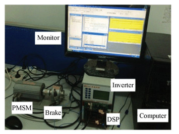
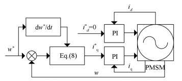
3 PMSM Experiments PMSM experimental servo platform is shown in Fig. 1, composed of four components: PMSM+magnetic brake, DSP control subsystem, power inverter and computer. PMSM model: 60CB020C, rated voltage: AC220V, rated power: 200 W, rated current: 1.27 A, rated speed: 3 000 r/min, pole pairs: np=4, rated torque: 0.64 N·m, stator resistance: Ro=13 Ω, inductance: Lqo=Ldo=Lo= 0.032H, flux linkage coefficient: Ψf =0.119 Wb, moment of inertia Jo=0.000 15 kg·m2, sliding friction coefficient Bo=0.000 1 N·m·s/rad. Magnetic brake model: CZ02, rated torque: 2 N·m, rated current: 0.5 A, slip power: 0.15 kW. Fig. 2 is the structure of PMSM system by CSMC with the magnetic field oriented control strategy. The speed loop by using CSMC and current loop by PI controller are cascade control. The speed loop sampling frequency is 1 kHz. The control parameters are: λ=8, ρ=15, from the Eq. (19) to get ?=0.03.
Fig.1
 Fig.1 PMSM experimental platform
 Fig.2
 Fig.2 Structure of CSMC system for PMSM
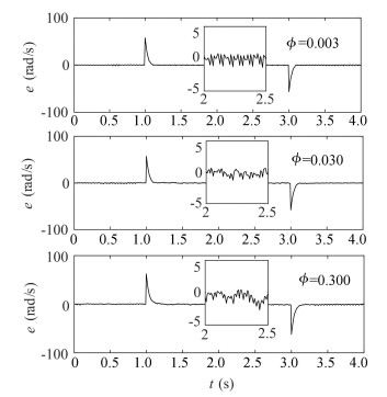
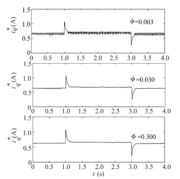
 In the experiments, the added load is 0.35 N·m, the speed reference input is: w*=40π rad/s when 0 < t < 1 s; w*=60π rad/s when 1 s < t < 3 s; w*=40π rad/s when 3 s < t < 4 s. Fig. 3 shows the system speed error e with different ? values. Fig. 4 shows iq* obtained by the CSMC method with the different ? values. Fig. 3 and Fig. 4 show that ?=0.003, iq* chatters seriously since this ? value is smaller than the uncertainties. The state trajectory of CSMC switches on the boundary ? in turn. This time, the system speed error e≤±2 rad/s; When ?=0.3, there is basically no high frequency chattering in iq*, since this ? value is larger than the uncertainties. The state trajectory is always stay on inside the boundary. The system speed error becomes a little larger, and reaches -3.0 rad/s; And the optimization value ?=0.03, iq* chattering is relatively small, but the system has a smallest stable state speed error, e≤±1.5 rad/s. Both figures indict that the larger the ? value is, the smaller the high frequency chattering is. The proposed method to optimize the parameter ? of the saturation function boundary layer does not need artificial setting. This optimization method for CSMC can obtain a compromise between the high frequency chattering of the system and ensure the system steady-state error.
Fig.3
 Fig.3 System speed error e with different ? values
 Fig.4
 Fig.4 Control variable iq* with different ? values
 4 Conclusions A parameter optimization method of the boundary layer of the saturation function is proposed to improve CSMC strategy. The boundary layer parameter is optimized as the expression of the switching gain and the sampling time, so as to avoid setting the boundary layer parameter artificially and improve the practicability of CSMC. The CSMC method is applied to the speed loop regulation in PMSM. The experimental results show that the boundary layer parameter optimization for the saturation function is effective for CSMC and can obtain a compromise between the high frequency chattering of the system and the system steady state error.
References
[1] Su J P, Wang C C. Complementary sliding control of non-linear system. International Journal of Control, 2002, 75(5): 360-368. DOI:10.1080/00207170110112250 (
 0)
0)[2] Zhang Xiaoyu, Su Hongye, Lu Renquan. Second-order integral sliding mode control for uncertain systems with control input time delay based on singular perturbation approach. IEEE Transactions on Automatic Control, 2015, 60(11): 3098-3100. DOI:10.1109/TAC.2015.2411991 (
 0)
0)[3] Ding Shihong, Wang Jiandian, Zheng Weixing. Second-order sliding mode control for nonlinear uncertain systems bounded by positive functions. IEEE Transactions on Industrial Electronics, 2015, 62(9): 5899-5909. DOI:10.1109/TIE.2015.2448064 (
 0)
0)[4] Liang C Y, Su J P. A new approach to the design of a fuzzy sliding mode controller. Fuzzy Sets & Systems, 2003, 139(1): 111-124. DOI:10.1016/S0165-0114(02)00480-3 (
 0)
0)[5] Sumantri Bambang, Naoki Uchiyama, Sano Shigenori. Least square based sliding mode control for a quad-rotor helicopter and energy saving by chattering reduction. Mechanical Systems and Signal Processing, 2016, 66-67: 769-784. DOI:10.1016/j.ymssp.2015.05.013 (
 0)
0)[6] Lin Faa-Jeng, Hwang Jonq-Chin, Chou Po-Huan, et al. FPGA-based intelligent-complementary sliding-mode control for PMLSM servo-drive system. IEEE Transactions on Power Electronics, 2010, 25(10): 2573-2587. DOI:10.1109/TPEL.2010.2050907 (
 0)
0)[7] Lianga Chi-Ying, Sub Juhng-Perng. A new approach to the design of a fuzzy sliding mode controller. Fuzzy Sets and Systems, 2003, 139(1): 111-124. DOI:10.1016/S0165-0114(02)00480-3 (
 0)
0)[8] Lian Ruey-Jing. Adaptive self-organizing fuzzy sliding-mode radial basis-function neural-network controller for robotic systems. IEEE Transactions on Industrial Electronics, 2014, 61(3): 1493-1503. DOI:10.1109/TIE.2013.2258299 (
 0)
0)[9] Huang Yi-Sheng, Sung Cheng-Chung. Function-based controller for linear motor control systems. IEEE Transactions on Industrial Electronics, 2010, 57(3): 1096-1105. DOI:10.1109/TIE.2009.2028290 (
 0)
0)[10] Gao Qing, Liu Lu, Feng Gang, et al. Universal fuzzy integral sliding-mode controllers for stochastic nonlinear systems. IEEE Transactions on Cybernetics, 2014, 44(12): 2658-2669. DOI:10.1109/TCYB.2014.2313028 (
 0)
0)[11] Saghafinia Ali, Ping Hew Wooi, Uddin Mohammad Nasir, et al. Adaptive fuzzy sliding-mode control into chattering-free IM drive. IEEE Transactions on Industry Applications, 2015, 51(1): 692-701. DOI:10.1109/TIA.2014.2328711 (
 0)
0)[12] Huang Y S, Sung C C. Implementation of sliding mode controller for linear synchronous motors based on direct thrust control theory. IET Control Theory Applications, 2010, 4(3): 326-338. DOI:10.1049/iet-cta.2008.0485 (
 0)
0)[13] Efimov Denis, Polyakov Andrey, Fridman Leonid, et al. Delayed sliding mode control. Automatica, 2016, 64: 37-43. DOI:10.1016/j.automatica.2015.10.055 (
 0)
0)[14] Patre B M, Londhe P S, Nagarale R M. Fuzzy sliding mode control for spatial control of large nuclear reactor. IEEE Transactions on Nuclear Science, 2015, 62(5): 2255-2265. DOI:10.1109/TNS.2015.2464677 (
 0)
0)[15] Chou Po-Huan, Lin Faa-Jeng, Chen Chin-Sheng, et al. DSP-based cross-coupled synchronous control for dual linear motors via intelligent complementary sliding mode control. IEEE Transactions on Industrial Electronics, 2012, 59(2): 1061-1073. DOI:10.1109/CHUSER.2012.6504322 (
 0)
0)