Author NameAffiliation
Yonghai Wang Beijing Institute of Space Long March Vehicle, China Academy of Launch Vehicle Technology , Beijing 100076, China
Gang Meng Beijing Institute of Space Long March Vehicle, China Academy of Launch Vehicle Technology , Beijing 100076, China
Jianlin Li Beijing Institute of Space Long March Vehicle, China Academy of Launch Vehicle Technology , Beijing 100076, China
Yongtao Shui Beijing Institute of Space Long March Vehicle, China Academy of Launch Vehicle Technology , Beijing 100076, China
Baogang Lu Beijing Institute of Space Long March Vehicle, China Academy of Launch Vehicle Technology , Beijing 100076, China
Abstract:
The attitude stability control of under-actuated spacecraft that used two reaction wheels in the presence of dynamic friction disturbance is handled. A novel improved control approach with a combination of a singular control law based on quaternion and extended state observer (ESO) is employed to establish a stabilization control so as to restrain the effect of friction. The corresponding simulation results demonstrate the highly stable accuracy and performance compensated dynamic friction. Furthermore, if there is a non-zero initial condition in under-actuated axis, the attitude stability can be enhanced with a magnetic torquer. Simulations for a nano-spacecraft denote a potential application value in pointing accuracy using two reaction wheels and a magnetic torquer.
Key words: nanospacecraft dynamic friction singular control linear extended state observer magnetic torquer
DOI:10.11916/j.issn.1005-9113.17152
Clc Number:TP273.2
Fund:
Yonghai Wang, Gang Meng, Jianlin Li, Yongtao Shui, Baogang Lu. An Improved Dynamic Friction Rejection Attitude Stability Control Strategy[J]. Journal of Harbin Institute of Technology (New Series), 2019, 26(5): 79-87. DOI: 10.11916/j.issn.1005-9113.17152

Corresponding author Baogang Lu, E-mail: lubaogang@163.com Article history Received: 2017-12-05
Contents Abstract Full text Figures/Tables PDF
An Improved Dynamic Friction Rejection Attitude Stability Control Strategy
Yonghai Wang, Gang Meng, Jianlin Li, Yongtao Shui, Baogang Lu


Beijing Institute of Space Long March Vehicle, China Academy of Launch Vehicle Technology, Beijing 100076, China
Received: 2017-12-05
Corresponding author: Baogang Lu, E-mail: lubaogang@163.com.
Abstract: The attitude stability control of under-actuated spacecraft that used two reaction wheels in the presence of dynamic friction disturbance is handled. A novel improved control approach with a combination of a singular control law based on quaternion and extended state observer (ESO) is employed to establish a stabilization control so as to restrain the effect of friction. The corresponding simulation results demonstrate the highly stable accuracy and performance compensated dynamic friction. Furthermore, if there is a non-zero initial condition in under-actuated axis, the attitude stability can be enhanced with a magnetic torquer. Simulations for a nano-spacecraft denote a potential application value in pointing accuracy using two reaction wheels and a magnetic torquer.
Keywords: nanospacecraft dynamic friction singular control linear extended state observer magnetic torquer
1 Introduction With the development of spacecraft technique in the modern, more and more requirements are proposed, such as higher reliability, lower cost, smaller size and so on. The attitude control techniques need to add some advanced capabilities including higher precision and agility, the much better performance of rejecting the uncertainty and disturbance, the capacity of keeping stabilization when some parts of the actuators lose effectiveness[1-2]. Recently, the attitude control of the under-actuated spacecraft exerts a tremendous fascination on researchers. The traditional attitude control normally assumes the spacecraft is full-actuated which means the number of control inputs is the same as the number of state variables[3]. The traditional attitude control normally assumes the spacecraft is full-actuated which is the number of control inputs equals to the number of the states[3]. However, under-actuated attitude control faces the challenge that the ability of control is insufficient. For this problem, more and more research literatures focus on the stabilization of the spacecraft with under-actuated conditions, such as attitude control with thrusters[4-5], control momentum gyroscopes[6-7], or two reaction wheels (RWs)[8-9]. Moreover, lots of theory researches have got a multitude of significant achievements, for instance, Mirshams[10-11] presented a tube-based predictive control strategy and applied it into the 3-axis stabilization attitude control of an asymmetric spacecraft which lacked control in one axes. Aiming at the cases where there are two available thrusters, the control laws are established for angular velocity and three-axis attitude stabilization utilizing the standard parameters of spacecraft attitude. In addition, the stability of the control laws proposed was proved employing Lyapunov stability criteria and LaSalle invariant theory strictly[12].
The full-state feedback control law and the inverse optimal attitude control areutilized to deal with the 3-axis attitude stabilization of a satellite equipped with two reaction wheels[13]. Moreover, the full-state feedback control law was validated to accomplish 3-axis stabilization just employing two control torques in-orbit test. As an improvement, a novel switching control law with bounded wheel speeds combing the generalized feedback linearization and a new saturated function was proposed to realize the attitude orientation control of spacecraft[14]. The extended control law was added with a new term to the control law presented by Horri and Palmer[13] and obtained the faster time responses and a lower steady state error[15].
However, the three control laws of the aforementioned method have not discussed the influence of the dynamic friction of the RWs and the external disturbance. In the practical application, the two types of disturbances cannot be neglected and have a negative effect on the attitude stabilization of under-actuated spacecraft. The extended state observer (ESO) technique proposed by Han was able to realize precise approximation for external bounded disturbance[16-17]. The linear and nonlinear ESO had been proved that the approximation error of ESO can converge into a small bounded neighborhood near the origin for the unknown disturbance[18-20]. Therefore, the novel improvement proposed in this paper combines a quaternion feedback control with ESO to develop a robust stabilization control law, which could avoid any potential complications caused by chattering.
In this paper, a quaternion feedback control combined with ESO is proposed to realize stabilization control which could restrain the effect of friction and bounded external disturbance while requiring no prior knowledge of them. Moreover, the ESO is used to approximate the dynamic friction disturbance. The asymptotic stability of closed-loop system is guaranteed which means the actual angular velocity and quaternion can be stabilized in the presence of friction. In Section 2, the attitude kinematics and dynamics of the under-actuated spacecraft in the presence of zero-total momentum and friction are formulated. Then, an attitude stability control strategy based on ESO subject to the effects of dynamic frictions and disturbance is proposed in Section 3. It is given the singular control law based on quaternion by the research of Horri and Palmer[13]. And it is proved that the estimation error of the linear ESO is bounded. Then a suitable Lyapunov function is proposed to prove the asymptotically stable of the closed-loop system. In Section 4, simulations based on a nano-spacecraft are performed to verify the robustness for the friction and external disturbance. The control method is shown to accurately slew and stabilize to a stable state with greater efficiency and pointing accuracy than existing controllers with the friction. It is also illustrated that the proposed control can significantly improve the convergence of stabilization state accuracy of a spacecraft subject to bounded square waves disturbance.
2 Attitude Kinematics and Dynamics for the Under-Actuated Spacecraft In this section, we just consider the spacecraft as a rigid body with two reaction wheels under the influence of dynamic friction and ignore the external unknown disturbance torques. Therefore, the attitude dynamics with the Euler's rotational equation is described by:
$\mathit{\boldsymbol{\dot H}} + \mathit{\boldsymbol{\omega }} \times \mathit{\boldsymbol{H}} = 0$ (1)
where ω =[ω1, ω2, ω3]T represents the angular velocity vector of the spacecraft in body fixed coordinate frame; H denotes the total angular momentum of the spacecraft including reaction wheels and is given by:
$\mathit{\boldsymbol{H}} = \mathit{\boldsymbol{J\omega }} + \mathit{\boldsymbol{h}}$ (2)
where J denotes inertia matrix of spacecraft, known positive definite and symmetric inertia tensor of spacecraft, h denotes the composite angular momentum of two reaction wheels.
In practical application, the reaction wheel model unavoidably exits the dynamic friction. It will be a disturbance form for the control torque of the reaction wheels. Consequently, it will be unreasonable in the absence of the friction. In this section, the influence of dynamic friction for attitude stability of the under-actuated spacecraft will be discussed. The differential equation that describes the motion which considers the dynamic friction[21] for reaction wheels is:
${\mathit{\boldsymbol{T}}_\mathit{\Omega }} = {\mathit{\boldsymbol{I}}_\mathit{\Omega }}\mathit{\boldsymbol{ \boldsymbol{\dot \varOmega} }} + b\mathit{\boldsymbol{ \boldsymbol{\varOmega} }} + c{\rm{sgn}}\left( \mathit{\boldsymbol{ \boldsymbol{\varOmega} }} \right)$ (3)
where TΩ=[TΩ1, TΩ2, TΩ3]T is the motor torque, IΩ=[IΩ1, IΩ2, IΩ3]T is the inertia matrix of the wheels. Ω=[Ω1, Ω2, Ω3]T represents the angular velocity of two wheels,
Combining Eq.(1), Eq.(2) and Eq.(3), the total control torque is provided by the reaction wheels, and consider
$\mathit{\boldsymbol{J\dot \omega }} = - \mathit{\boldsymbol{\omega }} \times \left( {\mathit{\boldsymbol{J\omega }} + \mathit{\boldsymbol{h}}} \right) + \mathit{\boldsymbol{u}} + {\mathit{\boldsymbol{d}}_f}$ (4)
where u =
It is well known that Euler angles may show singularity in use because the transformation from derivative of Euler angles to angular velocity is not defined globally. Considering the unit quaternions are globally defined in the attitude representation, they are popularly used for representing attitude of spacecraft in practice. Therefore, the kinematics of the spacecraft described in unit quaternion form as follows:
$\left\{ {\begin{array}{*{20}{l}}{\mathit{\boldsymbol{\dot q}} = \frac{1}{2}{q_4}\mathit{\boldsymbol{\omega }} - \mathit{\boldsymbol{\omega }} \times \mathit{\boldsymbol{q}}}\\{{{\dot q}_4} = - \frac{1}{2}{\mathit{\boldsymbol{\omega }}^{\rm{T}}}\mathit{\boldsymbol{q}}}\end{array}} \right.$ (5)
where the unit quaternion is q=[q1, q2, q3, q4]T, which is expressed as q=[qT, q4]T with q= [q1, q2, q3]T. q satisfies the relationship qTq +q42=1.
In this note, we mainly discuss the attitude stability of the under-actuated spacecraft with two reaction wheels. Hence, the zero-total angular momentum is applied in this case since it had been explained as emphasized in Ref.[13]. The zero-total angular momentum condition as:
$\mathit{\boldsymbol{J\omega }} + \mathit{\boldsymbol{h}} = 0$ (6)
In order to simplify the model concerned in this note, let us give some assumptions: J =diag(J1, J2, J3), two reaction wheels are set x-axis and y-axis of the body frame separately and the wheel on z-axis has lost effectiveness, leading h3=0, ω3=0.
Moreover, the dynamics by Eq.(4) and the kinematics by Eq.(5) can besimplified as:
$\left[ {\begin{array}{*{20}{c}}{{{\dot q}_1}}\\{{{\dot q}_2}}\\{{{\dot q}_3}}\\{{{\dot q}_4}}\end{array}} \right] = \frac{1}{2}\left[ {\begin{array}{*{20}{r}}{{q_4}}&{ - {q_3}}\\{{q_2}}&{{q_4}}\\{{q_1}}&{ - {q_2}}\\{ - {q_1}}&{ - {q_2}}\end{array}} \right]\left[ {\begin{array}{*{20}{l}}{{\omega _1}}\\{{\omega _2}}\end{array}} \right]$ (7)
$\left[ {\begin{array}{*{20}{c}}{{J_1}{{\dot \omega }_1}}\\{{J_2}{{\dot \omega }_2}}\end{array}} \right] = \left[ {\begin{array}{*{20}{l}}{{u_1}}\\{{u_2}}\end{array}} \right] + \left[ {\begin{array}{*{20}{l}}{{d_1}}\\{{d_2}}\end{array}} \right]$ (8)
where
3 Dynamic Friction Rejection Attitude Stability Control Strategy In this section, in order to handle the 3-axis attitude stability control just equipped with two reaction wheels, we take the system of spacecraft into two loops: 1) quaternion stability loop, called outer-loop. For this loop, a singular control law will be considered based on quaternion model to obtain the desired angular velocity which should achieve the attitude quaternion to be stable; 2) angular velocity tracking loop, called inner-loop. In this part, it should not only guarantee to track the desired angular velocity output from outer-loop, but also reject the dynamic friction. For the angular velocity tracking, feedback control law was proposed by Horri and Palmer[13], to address the problem. However, how to reject the friction of the wheels does not discuss in their research, indeed, there is rarely literature to concern this problem. In this note, the extended state observer (ESO) will be used to deal with the friction rejection.
3.1 Singular Control Law Based on Quaternion For this problem, a singular controller was considered in Ref.[13] in the case of an under-actuated spacecraft with two reaction wheels based on quaternion modeling. Therefore, the same control law is adopted as follows:
$\left\{ {\begin{array}{*{20}{l}}{{\omega _{d1}} = - k{q_1} + g\frac{{{q_2}{q_3}}}{{q_1^2 + q_2^2}}}\\{{\omega _{d2}} = - k{q_2} - g\frac{{{q_1}{q_3}}}{{q_1^2 + q_2^2}}}\end{array}} \right.$ (9)
where k>0 and g>0 are constants, ωd1 and ωd2 denote the desired angular velocity.
In Eq.(9), the fraction terms may become infinite when q1→0 and q2→0. Hence, in practical application, we can utilize the saturated function to solve the problem. Indeed, the angular nonlinear control law translates to:
$\left\{ {\begin{array}{*{20}{l}}{{\omega _{d1}} = - k{q_1} + g{\rm{sat}}\left( {\frac{{{q_2}{q_3}}}{{q_1^2 + q_2^2}},{\alpha _1}} \right)}\\{{\omega _{d2}} = - k{q_2} - g{\rm{sat}}\left( {\frac{{{q_1}{q_3}}}{{q_1^2 + q_2^2}},{\alpha _2}} \right)}\end{array}} \right.$ (10)
where sat(x, α) denotes the saturation function, α1>0, α2>0 are constant saturation limits.
${\rm{sat}}(x,\alpha ) = \left\{ {\begin{array}{*{20}{c}}{ - \alpha ,}&{x > \alpha }\\{x,}&{ - \alpha < x < \alpha }\\{ - \alpha ,}&{x < - \alpha }\end{array}} \right.$
3.2 Angular Velocity Tracking Control Based on ESO and Stability Proof For the inner-loop control problem, it should not only guarantee to track the desired angular velocity output fromouter-loop, but also reject the dynamic friction. A simple feedback law combined with the linear ESO technique will address this problem.
Assuming the dynamic friction function is differentiable and
$\left\{ {\begin{array}{*{20}{l}}{\underline {\mathit{\boldsymbol{\dot \omega }}} = \mathit{\boldsymbol{\underline u}} + \mathit{\boldsymbol{\underline d}} }\\{\underline {\mathit{\boldsymbol{\dot d}}} = \mathit{\boldsymbol{\chi }}}\end{array}} \right.$ (11)
where,
In this paper, a linear ESO is employed to approximate dynamic friction and analyse the convergence of its estimation error in the case of the model of friction is unknown. Since the actual angular velocity of wheels should be required bounded, in other words, Ω ≤ Ωmax, the dynamic friction is bounded. Therefore, the χ is also bounded and let
For Eq.(13), the corresponding linear ESO is given by:
$\left\{ {\begin{array}{*{20}{l}}{\underline {\mathit{\boldsymbol{\dot {\hat \omega} }}} = \underline {\mathit{\boldsymbol{\hat d}}} + {\beta _1}\left( {\mathit{\boldsymbol{\underline \omega }} - \underline {\mathit{\boldsymbol{\hat \omega }}} } \right) + \mathit{\boldsymbol{\underline u}} }\\{\underline {\mathit{\boldsymbol{\dot {\hat d}}}} = {\beta _2}\left( {\mathit{\boldsymbol{\underline \omega }} - \underline {\mathit{\boldsymbol{\hat \omega }}} } \right)}\end{array}} \right.$ (12)
where
Define the estimated errors
$\left\{ {\begin{array}{*{20}{l}}{\underline {\mathit{\boldsymbol{\dot {\tilde \omega} }}} = \underline {\mathit{\boldsymbol{\tilde d}}} - {\beta _1}\underline {\mathit{\boldsymbol{\tilde \omega }}} + \mathit{\boldsymbol{\underline u}} }\\{\underline {\mathit{\boldsymbol{\dot {\tilde d}}}} = \mathit{\boldsymbol{X}} - {\beta _2}\underline {\mathit{\boldsymbol{\tilde \omega }}} }\end{array}} \right.$ (13)
In Ref.[22], the performance has been proved. If the tuning parameter is suitable, the estimation error will be limited to the tiny and bounded region. Therefore, it can range the influence of the friction by adding into the control law. The tracking control law based on the linear ESO for angular velocity tracking is given as:
$\mathit{\boldsymbol{\underline u}} = - \mathit{\boldsymbol{\kappa }}\left( {\mathit{\boldsymbol{\underline \omega }} - {{\mathit{\boldsymbol{\underline \omega }} }_d}} \right) + {\underline {\mathit{\boldsymbol{\dot \omega }}} _d} - \underline {\mathit{\boldsymbol{\hat d}}} $ (14)
where
Theorem 1? Assumed
Proof? Choose a general Lyapunov function as:
$V = 2k\left( {1 - {q_4}} \right) + \frac{1}{2}\left\langle {\left( {\underline{\mathit{\boldsymbol{ \omega }}} - {{\underline{\mathit{\boldsymbol{ \omega }} }}_d}} \right),\left( {{\underline{\mathit{\boldsymbol{ \omega }}}} - {{\underline {\mathit{\boldsymbol{\omega }} }}_d}} \right)} \right\rangle $ (15)
where 〈, 〉 denotes the inner product and k>0 is aforementioned. Since the definition of the quaternion, the |q4| ≤1. Therefore, the V≥0 and the only equilibrium point is q4=1 and
The time derivative of this Lyapunov function is represented as:
$\dot V = - 2k{{\dot q}_4} + \left\langle {\left( {\underline{\mathit{\boldsymbol{ \omega }}} - {{\underline{\mathit{\boldsymbol{ \omega }} }}_d}} \right),\left( {\underline {\mathit{\boldsymbol{\dot \omega }}} - {{\underline {\mathit{\boldsymbol{\dot \omega }}} }_d}} \right)} \right\rangle $ (16)
Considering the attitude kinematics
${{\dot q}_4} = \frac{1}{2}k\left( {q_1^2 + q_2^2} \right) \ge 0$ (17)
Substituting the under-actuated attitude dynamics expressed by Eq.(11), the angular velocity tracking control law based the linear ESO indicated by Eq.(14) and the Eq.(17) into the Eq.(16), the time derivative of Lyapunov function develops into:
$\begin{array}{l}\dot V = - k\left( {q_1^2 + q_2^2} \right) + \left\langle {\left( {{\underline{\mathit{\boldsymbol{ \omega }}}} - {{{\underline{\mathit{\boldsymbol{ \omega }}}} }_d}} \right), - \kappa \left( {{\underline{\mathit{\boldsymbol{ \omega }}}} - {{{\underline{\mathit{\boldsymbol{ \omega }}}} }_d}} \right) + } \right.\\\;\;\;\;\;\left. {{\underline{\mathit{\boldsymbol{ d }}}} - \underline {\mathit{\boldsymbol{\hat d}}} } \right\rangle = - k\left( {q_1^2 + q_2^2} \right) - \kappa \left\langle {\left( {{\underline{\mathit{\boldsymbol{ \omega }}}} - {{{\underline{\mathit{\boldsymbol{ \omega }}}} }_d}} \right),} \right.\\\;\;\;\;\;\left. {\left( {{\underline{\mathit{\boldsymbol{ \omega }}}} - {{{\underline{\mathit{\boldsymbol{ \omega }}}} }_d}} \right)} \right\rangle + \left\langle {\left( {{\underline{\mathit{\boldsymbol{ \omega }}}} - {{{\underline{\mathit{\boldsymbol{ \omega }}}} }_d}} \right),\left( {{\underline{\mathit{\boldsymbol{ d }}}} - \underline {\mathit{\boldsymbol{\hat d}}} } \right)} \right\rangle \end{array}$ (18)
It reflects that the estimation error of the friction
4 Simulation and Analysis In this section, the feasibility of the control law will be now demonstrated by a numerical simulation using attitude dynamics and kinematics and proposed controller in Section 3. The simulation takes into two parts: the first and foremost, it demonstrates the controller derived with the model of spacecraft which only considers the friction. Secondly, it is shown that there is a sinusoidal disturbance as an external disturbance in the simulation to verify the proposed control to be the capability of rejecting the friction and external disturbance at the same time. It can illustrate effectively the robustness and practicability of the proposed control method. All of the simulations compare with a proportional feedback control law which is classical and distinguished.
The inertia matrix of the spacecraft in the simulations is given by
$\mathit{\boldsymbol{J}} = {\rm{diag}}\left( {0.1521,0.1521,0.0375} \right){\rm{kg}} \cdot {{\rm{m}}^2}$
and theinertia matrix of the reaction wheels is
${\mathit{\boldsymbol{I}}_\mathit{\Omega }} = {\rm{diag}}\left( {0.0015,0.0015,0.0015} \right){\rm{kg}} \cdot {{\rm{m}}^2}$
Friction parameter
$b = 5.16 \times {10^{ - 6}}{\rm{N}} \cdot {\rm{ms}},c = 8.795 \times {10^{ - 5}}{\rm{N}} \cdot {\rm{m}}$
The initial conditions: the initial attitude quaternion
$\mathit{\boldsymbol{\bar q}} = {\left[ {0.2236,0.2236, - 0.2236,0.9220} \right]^{\rm{T}}}$
and angular velocity ω =[0.1, 0.1]T rad/s.
The parameters of the linear ESO: β1=20, β2=40. The tuning parameters of the controller: k=0.16, g=0.32, κ =diag(1, 1) and the maximum torque umax=0.001 N·m. [Z1, Z2]T denotes the estimation of friction or external disturbance [d1, d2]T.
4.1 Simulations of Rejecting the Dynamic Friction In this part, a simple proportional feedback control law is shown as a comparison:
${\mathit{\boldsymbol{u}}_P} = \underline J \left[ { - \mathit{\boldsymbol{\kappa }}\left( {{\underline{\mathit{\boldsymbol{ \omega }}}} - {{\underline{{\mathit{\boldsymbol{ \omega }} }}}_d}} \right) + {{\underline {\mathit{\boldsymbol{\dot \omega }}} }_d}} \right]$ (19)
where J =diag (J1, J2).
The stability error for quaternion of the feedback control law based the linear ESO technique rejected the dynamic friction and the comparison control method with angular velocity feedback are demonstrated in Fig. 1. It is obvious that the tracking error of quaternion utilizing comparison control is stabilized to 5×10⁻³. However, the stability error of the method presented is much smaller, which has been converged to 1×10⁻⁴ order of magnitude. The compared result reflects that the proposed control has higher stabilization precision because of rejecting the friction by the linear ESO technique. The corresponding comparisons for angular velocity and control torque illustrate separately in Fig. 2 and Fig. 3. It demonstrates the estimation of the friction by the linear ESO in Fig. 4 and Fig. 5.
Fig.1
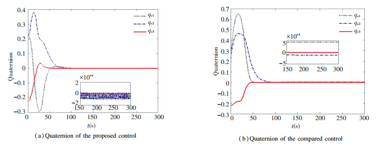 Fig.1 Quaternion error comparison with the friction
 Fig.2
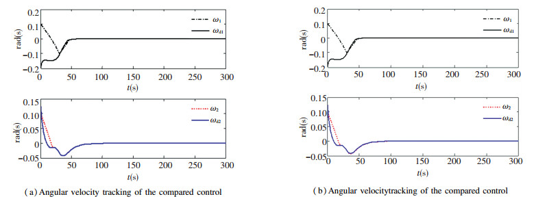 Fig.2 Angular velocity comparison with the friction
 Fig.3
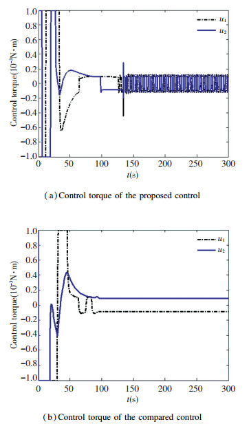 Fig.3 Control torque comparison with the friction
 Fig.4
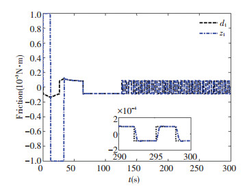 Fig.4 Estimation of the friction d1
 Fig.5
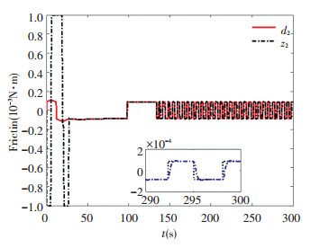 Fig.5 Estimation of the friction d2
 4.2 Simulations of Rejecting the External Disturbance In this part, we choose the square waves signal as the external disturbance. Let T=10 s is the switch period of the square waves. The model is described as:
$d = \left\{ {\begin{array}{*{20}{l}}{{{\left[ {\begin{array}{*{20}{c}}5&3\end{array}} \right]}^{\rm{T}}} \times {{10}^{ - 4}}{\rm{N}} \cdot {\rm{m}},\quad 2kT < t < (2k + 1)T}\\{ - {{[5\quad 3]}^{\rm{T}}} \times {{10}^{ - 4}}{\rm{N}} \cdot {\rm{m}},(2k + 1)T < t < (2k + 2)T}\end{array}} \right.$ (20)
The quaternion stability error of proposed control and the comparison method with the square wave disturbance are denoted in Fig. 6.
Fig.6
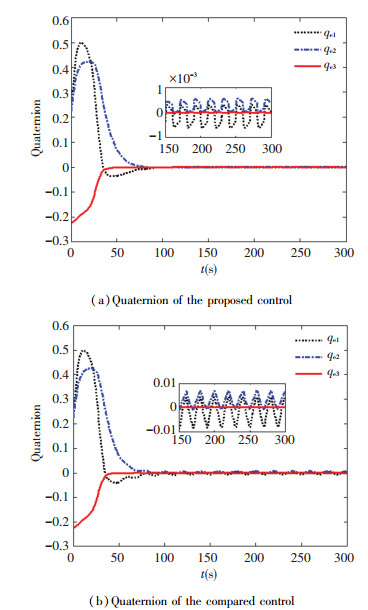 Fig.6 Quaternion error comparison with the friction
 The stabilization accuracy of the comparison control has been extremely bad, which is much bigger than the proposed control. However, the error of the proposed control maintains in a small region which is about 5×10⁻⁴ at the switch points and much smaller during the stable-state. The comparison of the angular is shown in the Fig. 7, it reflects that the angular velocity converges into zero except some switch points. It has been shown that the control torque of the proposed control is much smoother than the compared method in the Fig. 8. It has demonstrated that the estimated value of the external unknown disturbance by linear ESO approached the actual value in the Fig. 9 and Fig. 10.
Fig.7
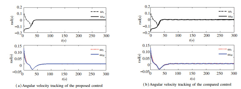 Fig.7 Angular velocity comparison with the friction
 Fig.8
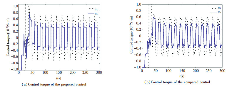 Fig.8 Control torque comparison with the friction
 Fig.9
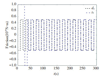 Fig.9 Estimation of the friction d1
 Fig.10
 Fig.10 Estimation of the friction d2
 5 Conclusions An improved dynamic friction rejection attitude stability control strategy, which including the singular control based on the quaternion and the angular velocity tracking control based on the linear ESO, is proposed in this paper. There is a significant improvement in convergence accuracy and control robustness with the effects of these uncertainties in comparison to a conventional control algorithm. Simulations have demonstrated that this control strategy can effectively stabilize a given state subject to external environmental disturbances and RWs friction. Furthermore, the control method proposed has the extremely excellent capacity to estimate the unknown disturbance with the linear ESO technique.
References
[1] Han Yu, Biggs James D, Cui Naigang. Adaptive fault-tolerant control of spacecraft attitude dynamics with actuator failures. Journal of Guidance Control and Dynamics, 2015, 38(10): 2033-2040. DOI:10.2514/1.G000921 (
 0)
0)[2] Ding Yibo, Guan Yinzi, Cui Naigang, et al. Robust disturbance rejection guidance law for autonomous rendezvous with tumbling non-cooperative spacecraft. Proceedings of the 2017 29th Chinese Control and Decision Conference. Piscataway: IEEE, 2017. 5346-5351. DOI: 10.1109/CCDC.2017.7979447. (
 0)
0)[3] Li Huiping, Yan Weisheng, Shi Yang. Continuous-time model predictive control of under-actuated spacecraft with bounded control torques. Automatica, 2017, 75: 144-153. DOI:10.1016/j.automatica.2016.09.024 (
 0)
0)[4] Godard, Kumar Krishna Dev, Zou An-Min. A novel single thruster control strategy for spacecraft attitude stabilization. Acta Astronautica, 2013, 86: 55-67. DOI:10.1016/j.actaastro.2012.12.018 (
 0)
0)[5] Zou An-min, Kumar Krishna Dev, de Ruiter Anton H J. Spacecraft attitude control using two control torques. Information Sciences, 2017, 408: 23-40. DOI:10.1016/j.ins.2017.04.032 (
 0)
0)[6] Kasai Shinya, Kojima Hirohisa, Satoh Mitsunori. Spacecraft attitude maneuver using two single-gimbal control moment gyros. Acta Astronautica, 2013, 84(3): 88-98. DOI:10.1016/j.actaastro.2012.07.035 (
 0)
0)[7] Gui Haichao, Vukovich George, Xu Shijie. Attitude stabilization of a spacecraft with two parallel control moment gyroscopes. Journal of Guidance, Control, and Dynamics, 2016, 39(3): 728-735. DOI:10.2514/1.G000982 (
 0)
0)[8] Han Congying, Guo Jian, Pecheva Alexandre. Nonlinear H∞ based underactuated attitude control for small satellites with two reaction wheels. Acta Astronautica, 2014, 104(1): 159-172. DOI:10.1016/j.actaastro.2014.07.036 (
 0)
0)[9] Kim Sungpil, Kim Youdan. Spin-axis stabilization of a rigid spacecraft using two reaction wheels. Journal of Guidance, Control, and Dynamics, 2001, 24(5): 1046-1049. DOI:10.2514/2.4818 (
 0)
0)[10] Mirshams M, Khosrojerdi M. Attitude control of an underactuated spacecraft using tube-based MPC approach. Aerospace Science and Technology, 2016, 48: 140-145. DOI:10.1016/j.ast.2015.09.018 (
 0)
0)[11] Mirshams M, Khosrojerdi M. Attitude control of an underactuated spacecraft using quaternion feedback regulator and tube-based MPC. Acta Astronautica, 2017, 132: 143-149. DOI:10.1016/j.actaastro.2016.11.033 (
 0)
0)[12] Wang Dongxia, Jia Yinghong, Jin Lei, et al. Control analysis of an underactuated spacecraft under disturbance. Acta Astronautica, 2013, 83: 44-53. DOI:10.1016/j.actaastro.2012.10.029 (
 0)
0)[13] Horri Nadjim M, Palmer Phil, Hodgart Stephen. Practical implementation of attitude control algorithms for an underactuated satellite. Journal of Guidance, Control, and Dynamics, 2012, 35(1): 40-45. DOI:10.2514/1.54075 (
 0)
0)[14] Gui Haichao, Jin Lei, Xu Shijie. Attitude maneuver control of a two-wheeled spacecraft with bounded wheel speeds. Acta Astronautica, 2013, 88: 98-107. DOI:10.1016/j.actaastro.2013.03.006 (
 0)
0)[15] Chaurais Jefferson R, Ferreira Henrique C, Ishihara Joao Y, et al. Attitude control of an underactuated satellite using two reaction wheels. Journal of Guidance, Control, and Dynamics, 2015, 38(10): 2010-2018. DOI:10.2514/1.G000145 (
 0)
0)[16] Han Jingqing. From PID to active disturbance rejection control. IEEE Transactions on Industrial Electronics, 2009, 56(3): 900-906. DOI:10.1109/TIE.2008.2011621 (
 0)
0)[17] Xia Yuanqing, Fu Mengyin, Li Chunming, et al. Active disturbance rejection control for active suspension system of tracked vehicles with gun. IEEE Transactions on Industrial Electronics, 2018, 65(5): 4051-4060. DOI:10.1109/TIE.2017.2772182 (
 0)
0)[18] Gao Z Q, Hu S H, Jiang F J. A novel motion control design approach based on active disturbance rejection. Proceedings of the 40th IEEE Conference on Decision and Control. Piscataway: IEEE, 2001. 4898-4907. DOI: 10.1109/CDC.2001.980980. (
 0)
0)[19] Xia Yuanqing, Zhu Zheng, Fu Mengyin, et al. Attitude tracking of rigid spacecraft with bounded disturbances. IEEE Transactions on Industrial Electronics, 2011, 58(2): 647-659. DOI:10.1109/TIE.2010.2046611 (
 0)
0)[20] Guo Baozhu, Zhao Zhiliang. On the convergence of an extended state observer for nonlinear systems with uncertainty. Systems & Control Letters, 2011, 60(6): 420-430. DOI:10.1016/j.sysconle.2011.03.008 (
 0)
0)[21] Cao Xibin, Wu Baolin. Indirect adaptive control for attitude tracking of spacecraft with unknown reaction wheel friction. Aerospace Science and Technology, 2015, 47: 493-500. DOI:10.1016/j.ast.2015.10.017 (
 0)
0)[22] Zheng Qing, Gaol Linda Q, Gao Zhiqiang. On stability analysis of active disturbance rejection control for nonlinear time-varying plants with unknown dynamics. Proceedings of the 46th IEEE Conference on Decision and Control. Piscataway: IEEE, 2007. 3501-3506. DOI: 10.1109/CDC.2007.4434676. (
 0)
0)