张成,王浩,江坤
(南京理工大学 能源与动力工程学院, 南京 210094)
摘要:
为研究机载布撒器囊式抛撒系统中气囊的抛撒性能,以初始为扁平结构的薄壁金属(304不锈钢)气囊为研究对象,采用流固耦合的方法对其膨胀抛弹过程展开数值仿真分析,得到囊内的流场特性和囊壁的应力响应,计算结果与试验吻合较好.分析了入口边界条件及气囊结构对抛撒结果的影响, 计算结果表明:气囊入口直径和入口边界条件是影响子弹分离速度和过载的关键因素,装药量、入口直径越大,子弹过载越大;一定装药量下,气囊入口直径不同时,子弹存在极限分离速度;气囊初始面积对子弹分离速度影响很小(仅4%),主要影响囊内的燃气压力,初始面积越大囊压越小,有利于降低囊壁的应力值.计算结果可为气囊结构的优化设计与工程实际应用提供重要参考.
关键词: 机载布撒器 扁平结构 薄壁金属气囊 流固耦合 抛撒
DOI:10.11918/j.issn.0367-6234.201611067
分类号:O354; V214.4
文献标识码:A
基金项目:
Analysis of the dispersing performance of a thin-walled metal gasbag based on fluid-structure interaction method
ZHANG Cheng,WANG Hao,JIANG Kun
(School of Energy and Power Engineering, Nanjing University of Science and Technology, Nanjing 210094, China)
Abstract:
To research the performance of gasbag used in bladder-type dispersal system, the fluid-structure interaction (FSI) model is established to simulate the inflating process of the metal gasbag (304 stainless steel) with a initially flat form. Then the dynamic response of bag's deformation and the changing law of internal flow field are acquired, and the results show a good agreement with the experimental results. Besides, the performances of gasbag with the change of its geometry and inlet conditions are investigated. The results show that the inlet diameter of gasbag and the inlet conditions are the key factor influencing the bullet's separating speed and overload. The larger the inlet diameter or the charge weight is, the greater the bullet's overload is. And when the bag's inlet diameter is different, there is an existence of the extreme separation speed of bullet with a certain amount of charge. The bag's initial area has a small impact on the change of speed (the difference is only 4%), while it affects the magnitude of the pressure of gas in the gasbag obviously. The larger the area, the smaller the pressure presents, which is beneficial to reducing the stress level of the wall of gasbag. So the calculation results can provide a mainly reference for the optimal design and engineering application of gasbag.
Key words: airborne dispenser flat form thin-walled metal gasbag fluid-structure interaction dispersion
张成, 王浩, 江坤. 薄壁金属气囊抛撒性能流固耦合分析[J]. 哈尔滨工业大学学报, 2018, 50(1): 121-126. DOI: 10.11918/j.issn.0367-6234.201611067.

ZHANG Cheng, WANG Hao, JIANG Kun. Analysis of the dispersing performance of a thin-walled metal gasbag based on fluid-structure interaction method[J]. Journal of Harbin Institute of Technology, 2018, 50(1): 121-126. DOI: 10.11918/j.issn.0367-6234.201611067.

作者简介 张成(1988—), 男, 博士研究生;
王浩(1961—), 男, 研究员, 博士生导师 通信作者 江坤, jk616@aliyun.com 文章历史 收稿日期: 2016-11-15
Contents -->Abstract Full text Figures/Tables PDF
薄壁金属气囊抛撒性能流固耦合分析
张成, 王浩, 江坤


南京理工大学 能源与动力工程学院, 南京 210094
收稿日期: 2016-11-15
作者简介: 张成(1988—), 男, 博士研究生;
王浩(1961—), 男, 研究员, 博士生导师
通信作者: 江坤, jk616@aliyun.com
摘要: 为研究机载布撒器囊式抛撒系统中气囊的抛撒性能,以初始为扁平结构的薄壁金属(304不锈钢)气囊为研究对象,采用流固耦合的方法对其膨胀抛弹过程展开数值仿真分析,得到囊内的流场特性和囊壁的应力响应,计算结果与试验吻合较好.分析了入口边界条件及气囊结构对抛撒结果的影响, 计算结果表明:气囊入口直径和入口边界条件是影响子弹分离速度和过载的关键因素,装药量、入口直径越大,子弹过载越大;一定装药量下,气囊入口直径不同时,子弹存在极限分离速度;气囊初始面积对子弹分离速度影响很小(仅4%),主要影响囊内的燃气压力,初始面积越大囊压越小,有利于降低囊壁的应力值.计算结果可为气囊结构的优化设计与工程实际应用提供重要参考.
关键词: 机载布撒器 扁平结构 薄壁金属气囊 流固耦合 抛撒
Analysis of the dispersing performance of a thin-walled metal gasbag based on fluid-structure interaction method
ZHANG Cheng, WANG Hao, JIANG Kun


School of Energy and Power Engineering, Nanjing University of Science and Technology, Nanjing 210094, China
Abstract: To research the performance of gasbag used in bladder-type dispersal system, the fluid-structure interaction (FSI) model is established to simulate the inflating process of the metal gasbag (304 stainless steel) with a initially flat form. Then the dynamic response of bag's deformation and the changing law of internal flow field are acquired, and the results show a good agreement with the experimental results. Besides, the performances of gasbag with the change of its geometry and inlet conditions are investigated. The results show that the inlet diameter of gasbag and the inlet conditions are the key factor influencing the bullet's separating speed and overload. The larger the inlet diameter or the charge weight is, the greater the bullet's overload is. And when the bag's inlet diameter is different, there is an existence of the extreme separation speed of bullet with a certain amount of charge. The bag's initial area has a small impact on the change of speed (the difference is only 4%), while it affects the magnitude of the pressure of gas in the gasbag obviously. The larger the area, the smaller the pressure presents, which is beneficial to reducing the stress level of the wall of gasbag. So the calculation results can provide a mainly reference for the optimal design and engineering application of gasbag.
Key words: airborne dispenser flat form thin-walled metal gasbag fluid-structure interaction dispersion
作为一种在敌方地面防区外发射的模块化多用途空对地武器,机载布撒器以快速、远程、精确打击的优良性能逐渐成为摧毁或封锁机场、导弹发射架(井)、港口、装甲编队等目标的有效武器,是世界各军事大国广泛重视并应用的先进面毁伤武器.布撒系统是布撒器中抛撒子弹药对目标实施攻击的关键子系统, 其结构及子弹药布撒技术是决定布撒器攻击效能的关键因素之一.燃气囊式抛撒技术相对其他常用动力源(电液、电磁)以功率-质量比大,可靠性高,结构简单,系统体积小、重量轻,成本低,使用维护方便等优点被广泛地采用[1].
目前,国内外对囊式抛撒技术开展了大量研究,王浩、徐文旭、陶如意等[2-4]分别基于集总参数法建立了内燃式气囊抛撒子弹过程的内弹道数学模型, 并对比了试验结果, 验证了模型的有效性,计算结果表明采用内燃式气囊抛撒技术,子弹药具有较高的分离速度,同时过载较大(>2 000g);张博孜[5-6]采用CE/SE算法建立了二维两相流内弹道模型,研究了内燃式抛撒装置内燃气流场的流动特性和压力分布规律,并分析设置扰流板对燃气流场的影响,以研究对子弹翻转角速度的控制技术.相比内燃式抛撒技术,外燃式抛撒方式由燃气分配器向囊内充气,通过对分配器的调节可以实现子弹对不同分离速度的要求,同时具有较低的过载(< 1 000 g).王帅[7]通过静态承压试验和动态抛撒试验对橡胶/芳纶复合材料气囊的抛撒性能进行了较全面的研究,结果表明该外燃式抛撒气囊承压能力较强, 抛撒弹道稳定且过载较小(350g左右);为降低囊内压力峰值和抛撒过载,房玉军等[8]采用氮气发生剂作为抛撒药进行抛撒实验,并研究子弹抛撒速度、气囊压力与药量之间的关系, 以及母弹舱体结构强度与气囊强度对子弹抛撒速度的影响;Dreher等[9-10]实验研究了低压气囊直径与囊内压力峰值、子弹加速度间的影响关系,同时基于气体动力学理论研究了抛撒过程中气囊的动态响应.可见,对囊式抛撒技术的研究工作仍以通过动态抛撒试验和抛撒内弹道的计算获得子弹分离状态为主,对膨胀过程中囊内流场的形成和发展研究较少,研究和掌握囊内的流场变化以及气囊的结构响应将对实际的工程应用具有重要意义.
本文以初始扁平结构的薄壁金属(304不锈钢)气囊(外燃式)为研究对象,通过承压试验已验证其承压强度>2.2 MPa,比相同尺寸的橡胶/芳纶气囊承压强度提高了50%,动态抛撒试验结果表明, 采用平面抛撒的方式, 囊体能保持完整性,为子弹药提供足够的分离速度.为进一步掌握薄壁金属气囊的动态抛撒性能,揭示囊内流场的发展规律,分析燃气压力下囊壁经历大变形的应力响应,以及气囊结构参数对抛撒过程的影响,本文基于ADINA有限元分析软件对薄壁金属气囊膨胀抛弹的流固耦合过程进行仿真与分析.
1 流固耦合控制方程 1.1 流体域薄壁金属气囊膨胀抛弹过程中,囊壁作为流固耦合的边界将经历较大的变形,流体域N-S方程的任意拉格朗日欧拉(ALE)描述如下:
$\frac{\partial }{{\partial t}}{\smallint _V}\mathit{\boldsymbol{U}}{\rm{d}}V + {\smallint _V}\mathit{\boldsymbol{w}} \cdot \nabla \mathit{\boldsymbol{U}}{\rm{d}}V + {\oint _S}\left( {\mathit{\boldsymbol{F}} + \mathit{\boldsymbol{G}}} \right) \cdot \mathit{\boldsymbol{n}}{\rm{d}}S = {\smallint _V}\mathit{\boldsymbol{Q}}{\rm{d}}V,$ (1)
$\left\{ \begin{array}{l}\mathit{\boldsymbol{U = }}\left[ {\begin{array}{*{20}{c}}{{\rho _{\rm{f}}}}\\{{\rho _{\rm{f}}}\mathit{\boldsymbol{v}}}\\{{\rho _{\rm{f}}}E}\end{array}} \right],\mathit{\boldsymbol{F}} = \mathit{\boldsymbol{vU}} + \left[ {\begin{array}{*{20}{c}}\mathit{\pmb{0}}\\{p\mathit{\boldsymbol{I}}}\\{\mathit{\boldsymbol{v}}p}\end{array}} \right],\\\mathit{\boldsymbol{G}} = \left[ {\begin{array}{*{20}{c}}\mathit{\pmb{0}}\\{ - \mathit{\boldsymbol{\sigma }}}\\{ - \mathit{\boldsymbol{\sigma }} \cdot \mathit{\boldsymbol{v}} + \mathit{\boldsymbol{q}}}\end{array}} \right],\mathit{\boldsymbol{Q}} = \left[ {\begin{array}{*{20}{c}}\mathit{\pmb{0}}\\{{\mathit{\boldsymbol{f}}_{\rm{b}}}}\\{{\mathit{\boldsymbol{f}}_{\rm{b}}} \cdot \mathit{\boldsymbol{v + }}{\rho _{\rm{f}}}{q_{\rm{b}}}}\end{array}} \right],\end{array} \right.$ (2)
$p = {\rho _{\rm{f}}}\left({{C_p} -{C_V}} \right)\theta.$ (3)
式中:v和w分别为流体的绝对速度和相对于网格移动的速度,ρf为流体密度,T为温度, fb和qb分别为流体所受体力和单位体积产热量,q为外部传热热量.流体本构方程表示为τ =-pI+σ,其中σ =2μe+λ▽· vI,μ和λ分别为第1、2黏性系数.
采用基于Petrov-Galerkin变分法的FCBI单元法对方程(1)~(3)进行如下离散:
${f_\mathit{\Omega }}\mathit{\boldsymbol{Y}}\left[ {\frac{{\partial \mathit{\boldsymbol{U'}}}}{{\partial t}} + \mathit{\boldsymbol{w}} \cdot \nabla \mathit{\boldsymbol{U'}}{\rm{ + }}\nabla \cdot \left( {\mathit{\boldsymbol{F'}}{\rm{ + }}\mathit{\boldsymbol{G'}}} \right) - \mathit{\boldsymbol{Q'}}} \right]{\rm{d}}\mathit{\Omega }{\rm{ = }}\mathit{\pmb{0}},$
$\mathit{\boldsymbol{Y = }}\left[ {\begin{array}{*{20}{c}}q\\w\\w\end{array}} \right],\mathit{\boldsymbol{U'}}{\rm{ = }}\left[ {\begin{array}{*{20}{c}}\rho \\{\rho \mathit{\boldsymbol{u}}}\\{\rho {C_V}\theta }\end{array}} \right],$
$F' = \left[ {\begin{array}{*{20}{c}}{\rho + \mathit{\pmb{0}}}\\{\rho \mathit{\boldsymbol{uv}}{\rm{ + }}p\mathit{\boldsymbol{I}}}\\{\rho {C_V}\mathit{\boldsymbol{u}}\phi {\rm{ + }}\mathit{\boldsymbol{u}}p}\end{array}} \right],\mathit{\boldsymbol{G' = }}\left[ {\begin{array}{*{20}{c}}\mathit{\pmb{0}}\\{ - \mathit{\boldsymbol{\sigma }}}\\{ - \mathit{\boldsymbol{\sigma }} \cdot \mathit{\boldsymbol{u}}{\rm{ + }}\mathit{\boldsymbol{q}}}\end{array}} \right],$
$\mathit{\boldsymbol{Q' = }}\left[ {\begin{array}{*{20}{c}}\mathit{\pmb{0}}\\{{\mathit{\boldsymbol{f}}_{\rm{b}}}}\\{{\mathit{\boldsymbol{f}}_{\rm{b}}} \cdot \mathit{\boldsymbol{u}}{\rm{ + }}{\rho _{\rm{f}}}{q_{\rm{b}}}}\end{array}} \right].$
FCBI单元算法[11-14]采用Galerkin法对非对流项进行插值函数离散,为避免对流项在高Reynolds数和高Peclet数下的不稳定性,基于当地Reynolds数和Peclet数建立权函数.
1.2 结构域结构域平衡方程为
${\rho _{\rm{s}}}\frac{{{{\rm{d}}^2}{\mathit{\boldsymbol{u}}_{\rm{s}}}}}{{{\rm{d}}{t^2}}} + \eta \frac{{{\rm{d}}{\mathit{\boldsymbol{u}}_{\rm{s}}}}}{{{\rm{d}}t}} = \nabla \cdot {\mathit{\boldsymbol{\sigma }}_{\rm{s}}} + {\rho _{\rm{s}}}{\mathit{\boldsymbol{f}}_{\rm{s}}},$
材料模型为双线性本构,增量形式的表述为
$\Delta {\mathit{\boldsymbol{\sigma }}_{\rm{s}}} = {\mathit{\boldsymbol{D}}_{{\rm{ep}}}}\left( {^t\mathit{\boldsymbol{\sigma }}{,^t}E} \right)\Delta {\mathit{\boldsymbol{\varepsilon }}_{\rm{s}}},$
接触方程为
$^t{\mathit{\boldsymbol{F}}^{\rm{B}}} = { - ^t}{\mathit{\boldsymbol{F}}^{\rm{A}}}.$
式中:us为位移变量,ρs为结构密度,η为阻尼系数,fs为单位体积所受体力,Δσs和Δεs分别为应力、应变增量,Dep(tσ, tE)为t时刻的弹性矩阵. tFB和FA分别为t时刻主、从接触点的受力.
1.3 耦合条件在流固耦合边界
$\underline {{\mathit{\boldsymbol{d}}_{\rm{f}}}} = \underline {{\mathit{\boldsymbol{d}}_{\rm{s}}}} ,\underline {{\mathit{\boldsymbol{f}}_{\rm{f}}}} = \underline {{\mathit{\boldsymbol{f}}_{\rm{s}}}} .$
式中:d、f分别为
耦合方程表述为
$\mathit{\boldsymbol{F}}\left[ \mathit{\boldsymbol{X}} \right] = \left( {\begin{array}{*{20}{c}}{{\mathit{\boldsymbol{F}}_{\rm{f}}}\left[ {{\mathit{\boldsymbol{X}}_{\rm{f}}},\underline {{\mathit{\boldsymbol{d}}_{\rm{s}}}} \left( {{\mathit{\boldsymbol{X}}_{\rm{s}}}} \right)} \right]}\\{{\mathit{\boldsymbol{F}}_{\rm{s}}}\left[ {{\mathit{\boldsymbol{X}}_{\rm{s}}},\underline {{\mathit{\boldsymbol{f}}_{\rm{f}}}} \left( {{\mathit{\boldsymbol{X}}_{\rm{f}}}} \right)} \right]}\end{array}} \right) = 0.$
式中:Xf和Xs分别为流体域和固体域解向量.采用Euler法对耦合方程进行时间积分,每个时间步内为Newton-Raphson迭代.
2 抛撒过程流固耦合分析 2.1 有限元模型流体域如(图 1(a))所示,入口的边界为燃气压力和温度(图 2所示).固体域(图 1(b))中,将填充物、子弹和背板考虑为刚性材料,采用实体单元离散,囊壁和弹箍材料为304不锈钢,采用双线性弹塑性本构描述,厚度分别为0.2 mm和1.0 mm,采用壳单元离散.求解域的物性参数分别如表 1所示.
Figure 1
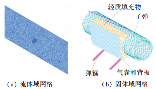 图 1 抛撒有限元模型 Figure 1 The model of the gasbag inflating to disperse bomblets
 Figure 2
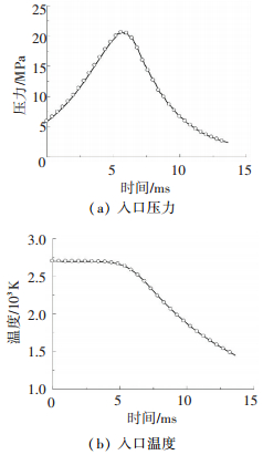 图 2 入口边界条件 Figure 2 Inlet conditions of the gasbag
 表 1
(J·kg-1·K-1) 燃气热导率/
(W·m-1·K-1) 燃气黏性系数/
(Pa·s) 囊壁弹性模量/
GPa 泊松比 囊壁屈服强度/
GPa 囊壁硬化模量/
GPa
1.24 1 847 0.167 8.13e-5 193 0.3 0.224 1.62
表 1 薄壁金属气囊抛撒系统的材料参数 Table 1 Material properties of the dispersing system
2.2 结果分析图 3给出了囊内流场动边界上测压孔处的压力变化曲线,及与试验结果的对比,二者吻合较好,表明本文建立的流固耦合模型可以有效地描述薄壁金属气囊的抛撒过程.
Figure 3
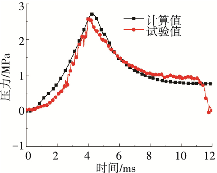 图 3 囊内压力计算值与试验的对比 Figure 3 The calculated pressure in contrast with experimental data
 2.2.1 囊内流场分析图 4给出了抛撒过程中囊内流场的形成与发展过程.图中显示燃气射流高速流出冲击上层囊壁,并在气囊嘴出口周围形成了轴对称的涡流结构,射流影响区主要受上层囊壁的位移及入口边界条件的影响. 6 ms之前,上层囊壁位移较小,正对气囊嘴位置存在较大的逆压梯度,涡流核心被挤压靠近下层囊壁, 强度较小;随着位移的增加,射流距离增大,射流核心马赫数增大,两侧涡流影响区增大,对囊壁的冲击明显减弱,射流区外压力分布较为均匀;抛撒末期,囊内压力分布相对均匀,入口压力与囊内压力差较小,使射流效果减弱,上层囊壁不再受到射流的冲击影响,两侧涡流强度较弱,且囊壁的回弹使两侧燃气出现了回流现象.
Figure 4
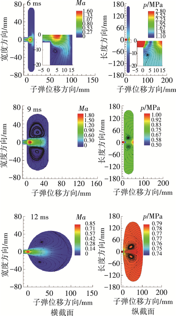 图 4 囊内流场马赫数、压力分布及流线图 Figure 4 Changes of Mach number, pressure distribution and streamline in the gasbag
 图 5显示了子弹运动不同位移时,上层囊壁沿长度方向(即子弹轴向)的压力分布呈现中间较高并向两端递减的趋势.当位移<36 mm时,上层囊壁受燃气射流冲击明显,位移越小射流影响区越大,位移>65 mm后,冲击效应不明显,囊壁上压力分布较为均匀.
Figure 5
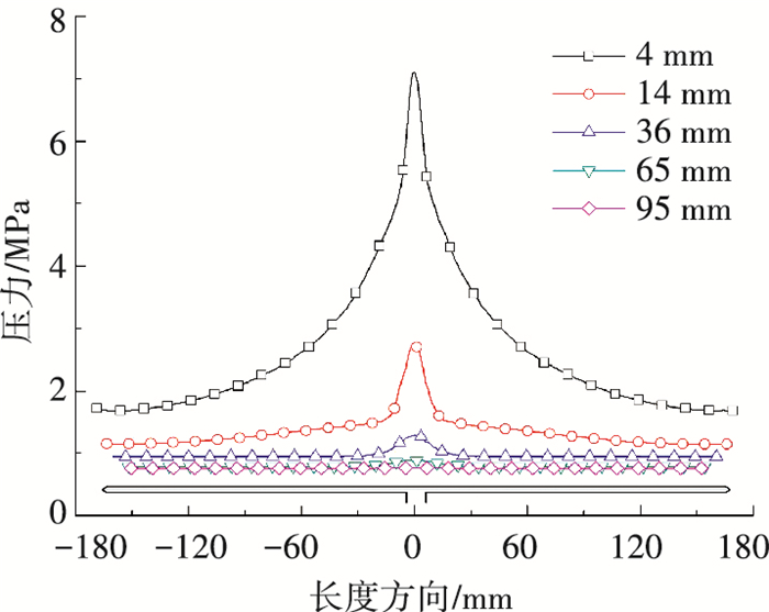 图 5 压力沿气囊长度方向的分布 Figure 5 Pressure distribution along the length direction
 2.2.2 囊壁应力分析图 6为囊壁上应力分布图,显示应力主要集中于气囊长边的中部位置. 图 7为该处的应力变化曲线,显示该位置应力随时间呈增长的趋势,在抛撒结束时刻应力值达到最大,为482 MPa,因此需要对薄壁金属气囊进行必要的加工工艺设计,以保证长边具有足够的焊缝强度
Figure 6
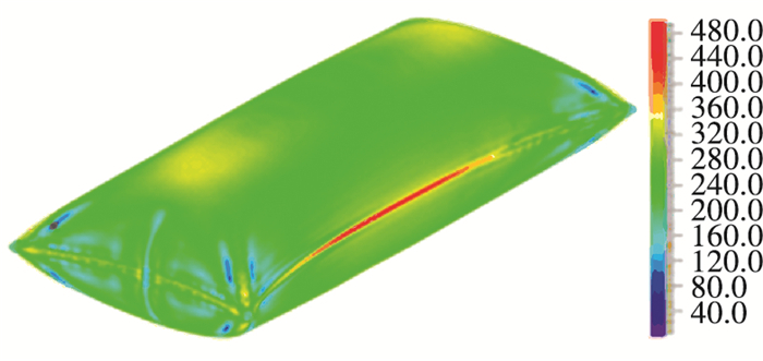 图 6 囊壁应力分布 Figure 6 The stress distribution on the gasbag wall
 Figure 7
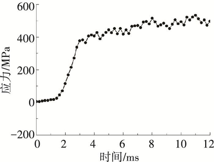 图 7 应力变化曲线 Figure 7 The stress changing history
 2.3 气囊结构参数对抛撒结果的影响为进一步掌握薄壁金属气囊的抛撒性能,下面分析入口边界条件及气囊结构参数对抛撒结果的影响.入口边界条件根据不同装药量(5、6、7 g)下的内弹道[15]计算得到.
2.3.1 气囊入口直径d图 8给出了气囊不同入口直径对子弹分离速度、过载、最大平均压力pmax、抛撒结束时刻压力pfinal以及囊壁内最大应力σ的影响.
Figure 8
 图 8 气囊入口直径对抛撒结果的影响 Figure 8 The effect of inlet diameter on the results
 由图 8(a)、(b)可知,d < 14 mm时,装药量、入口直径越大,子弹分离速度和过载随之增大,这是因为装药量和入口直径决定了流入囊内的燃气总能,总能量越大,通过气囊转化成的子弹抛撒动能越大;相同药量下,子弹分离速度和过载的增长率随入口直径的增大而减小.当d >14 mm时,6、7 g装药量下的分离速度增加幅度仅在2%以内,而5 g装药量下的分离速度出现了下降的趋势,这是因为采用过大的入口直径时入口压力较低,减少了流入囊内的燃气总量;因此说明一定装药量下,气囊入口直径不同时,子弹存在极限分离速度.
图 8(c)中入口直径与囊内压力的关系表明同等装药量下,囊内压力随入口直径d的增加而增大,其中pmax的增大较为显著,pfinal增加较小且当d≥12 mm后几乎不再增加.其中5 g装药量下,d=16 mm时,流入囊内燃气总量的减少使pfinal有所下降.由于囊壁最大应力σ出现在抛撒结束时刻,其大小将受到pfinal影响,图 8(d)显示不同装药量和入口直径下,σ的变化趋势和图 8(c)中的pfinal相近.
综上,同等装药量下,入口直径过小将限制流入囊内的燃气流量,降低子弹的分离速度;过大的入口直径对提高分离速度贡献较小,甚至会使其下降,同时增加了对子弹的过载.
2.3.2 气囊长度L气囊初始形态为扁平结构,初始面积s0决定了膨胀过程中对子弹的推力面积s和囊内容积V的大小,为分析s0对抛撒结果的影响,取d=10 mm进行分析.考虑气囊宽度受到弹径的限制,s0的变化通过气囊长度L的改变实现,图 9给出了计算结果.
Figure 9
 图 9 气囊长度对抛撒结果的影响 Figure 9 The effect of gasbag length on the results
 气囊对子弹药做的功为W=∫pn·sdl,l为子弹药运动方向上的位移.装药量和气嘴面积一定的条件下,进入囊内的燃气总能基本不变,pn和V接近反比关系(如图 9(c)所示),W变化较小,因此气囊初始面积对子弹分离速度的影响较小,差异仅在4%以内,如图 9(a)所示.
图 9(b)为装药量和气嘴面积一定的条件下,子弹过载随气囊面积s0增大而增大,但增加幅度不大且增长率随之减小;药量的增加会增大过载.
图 9(d)为气囊长L对囊壁最大应力值的影响.过小的L明显提高了囊内压力,囊壁应力显著增加,其中7 g药量下囊壁应力已经超过了材料的极限值,在抛撒结束前发生破裂,将会降低子弹抛撒弹道的可靠性和稳定性.同样装药条件下初始面积越大囊压越小,最大应力值越小,有利于降低囊壁的应力值,避免囊壁的提前破坏.
3 结论1) 建立金属薄壳气囊抛撒过程的流固耦合模型,通过与试验结果的对比验证了模型的有效性,揭示了囊内流场结构的形成和发展过程,以及上层囊壁上的压力分布和囊壁的应力分布规律.
2) 分析得到了抛撒药量和气囊结构参数(入口直径和气囊长度)对抛撒过程中囊内压力、分离速度、子弹过载及囊壁最大应力等重要参数的影响规律,为该结构气囊的工程应用提供了重要参考.
3) 本文主要对抛撒后子弹无翻转角速度的情况进行了分析,后续将进行气囊为子弹提供出舱姿态角和翻转角速度方面的研究工作.
参考文献
[1]王在成, 姜春兰, 蔡汉文. 机载布撒器子弹药抛撒系统总体技术研究[J].战术导弹技术, 2000(2): 23-30.
WANG Zaicheng, JIANG Chunlan, CAI Hanwen. Study of the submunition dispensing system of airborne dispenser[J].Tactical Missile Technology, 2000(2): 23-30.DOI: 10.16358/j.issn.1009-1300.2000.02.005
[2]王浩. 子母弹内燃式气囊抛撒模型及计算机仿真[J].兵工学报, 2001, 22(2): 178-181.
WANG Hao. A model for the firing process of the internal-combustion gasbag submunition and its simunitation[J].Acta Armamenttarii, 2001, 22(2): 178-181.DOI: 10.3321/j.issn:1000-1093.2001.02.009
[3]徐文旭, 张靖, 齐占元, 等. 子母弹抛撒内弹道建模及仿真[J].兵工学报, 2006, 27(5): 797-801.
XU Wenxu, ZHANG Jing, QI Zhanyuan, et al. The modeling and simulation of interior trajectory for cluster munition dispersing[J].Acta Armamenttarii, 2006, 27(5): 797-801.DOI: 10.3321/j.issn:1000-1093.2006.05.007
[4]陶如意, 叶涛, 吴艳滨, 等. 波纹管式抛撒机构抛撒过程建模及仿真[J].南京理工大学学报, 2014(2): 205-209.
TAO Ruyi, YE Tao, WU Yanbin, et al. Model and simulation of dispersing process of steel bag dispersal mechanism[J].Journal of Nanjing University of Science and Technology, 2014(2): 205-209.DOI: 10.3969/j.issn.1005-9830.2014.02.004
[5]张博孜. 子母弹中心燃气式抛撒内弹道过程研究[D]. 南京: 南京理工大学, 2015.
ZHANG Bozi. Study of the interior ballistic process of central-gas submunition dispersal research[D]. Nanjing: Nanjing University of Science and Technology, 2015.http://www.wanfangdata.com.cn/details/detail.do?_type=degree&id=Y2976453
[6]张博孜, 王浩, 王珊珊. 含扰流装置的中心燃气式抛撒内弹道过程的数值模拟[J].爆炸与冲击, 2015, 35(2): 208-214.
ZHANG Bozi, WANG Hao, WANG Shanshan. Numerical simulation on interior ballistic of central combustion gas dispersing system with spoiler[J].Explosion and Shock Waves, 2015, 35(2): 208-214.DOI: 10.11883/1001-1455(2015)02-0208-07
[7]王帅. 子母战斗部囊式抛撒系统实验研究及数值仿真[D]. 南京: 南京理工大学, 2013.
WANG Shuai. Experimental and simulation study on the explosive cluster warhead dispersion system[D]. Nanjing: Nanjing University of Science and Technology, 2013: 33-51.http://cdmd.cnki.com.cn/article/cdmd-10288-1013354357.htm
[8]房玉军, 蒋建伟, 万丽珍, 等. 采用氮气发生剂的子弹药气囊抛撒实验研究[J].兵工学报, 2006, 27(5): 883-886.
FANG Yujun, JIANG Jianwei, WAN Lizhen, et al. Experimental study on submunition dispenser with gasbag and nitrogen generant[J].Acta Armamenttarii, 2006, 27(5): 883-886.DOI: 10.3321/j.issn:1000-1093.2006.05.025
[9] DREHER P, CANFIELD R, MAPLE R. Experimental dynamic response of a solid object to various diameter low pressure airsbags[C]//47th AIAA/ASME/ASCE/AHS/ASC Structures, Structural Dynamics and Materials Conference. Reston: AIAA, 2006: AIAA-2006-1658. DOI: 10.2514/6.2006-1658.
[10] DREHER P, CANFIELD R, MAPLE R. Dynamic response of a munition to a low pressure airbag[C]//46th AIAA/ ASME/ASCE/AHS/ASC Structures, Structural Dynamics and Materials Confe-rence. Reston: AIAA, 2005: AIAA-2005-2031. DOI: 10.2514/6.2005-2031.
[11]KOHNO H, BATHE K J. A flow condition based interpolation finite element procedure for triangular grids[J].International Journal for Numerical Methods in Fluids, 2006, 51(6): 673-699.DOI: 10.1002/fld.1246
[12]BATHE K J, PONTAZA J P. A flow-condition-based interpolation mixed finite element procedure for higher reynolds number fluid flow[J].Mathematical Models and Methods in Applied Sciences, 2002, 12(4): 525-539.DOI: 10.1142/S0218202502001775
[13] BATHE K J. Finite element procedures[M]. 2nd ed. Upper Saddle River: Prentice Hall, 2006: 677-691.
[14]ZHANG Cheng, NING Huijun, JIANG Kun, et al. The dynamical fsi simulation for bellows inflating to disperse bomblets[J].Journal of Harbin Institute of Technology (New Series), 2016, 23(2): 51-58.DOI: 10.11916/j.issn.1005-9113.2016.02.008
[15]金志明. 枪炮内弹道学[M]. 北京: 北京理工大学出版社, 2004: 293-297.
JIN Zhiming. Interior Ballistics of Guns[M]. Beijing: Beijing Institute of Technology Press, 2004: 293-297.
