王家序1,2,胡如康1,周广武1,张振华1,裴欣1
(1.四川大学 空天科学与工程学院,成都 610065;2.机械传动国家重点实验室(重庆大学),重庆 400044)
摘要:
为了给轮齿啮合区的加速寿命试验提供理论依据,更好地指导产品优化设计,以某型号谐波减速器为分析对象,基于包络理论求出柔轮与刚轮的齿廓方程,分析了啮合点的曲率半径、卷吸速度以及啮合区受载情况,综合考虑啮合区的宏观几何、真实表面粗糙度等因素,建立了柔轮与刚轮啮合区的混合润滑模型,通过分析润滑区膜厚比、摩擦因数等参数,定量研究了转速和温度对润滑性能的影响.结果表明:转速越高,平均油膜厚度和膜厚比越大,接触载荷比和接触面积比越小,润滑性能越好.当转速高于2 200 r/min时,啮合区由边界润滑变为混合润滑,接触载荷比和接触面积比较50 r/min时减小90%以上,摩擦因数减小一半以上,将转速控制在2 200 r/min以上有利于改善润滑状况;随着啮合区温度的升高,平均油膜厚度和膜厚比逐渐减小,接触载荷比和接触面积比逐渐增大,润滑状况逐渐变差.温度为60 ℃时,摩擦因数较10 ℃增加一倍以上,接触载荷比和接触面积比增加一倍以上,需严格控制谐波减速器工作温度在60 ℃以下.
关键词: 谐波减速器 双圆弧齿廓 共轭区域 表面接触 混合润滑
DOI:10.11918/j.issn.0367-6234.201709160
分类号:TH117.2
文献标识码:A
基金项目:国家高技术研究发展计划(863计划)资助(2015AA043001)
Analysis on mixed lubrication at the conjugate meshing domain of harmonic gear with double-circular-arc tooth profile
WANG Jiaxu1,2,HU Rukang1,ZHOU Guangwu1,ZHANG Zhenhua1,PEI Xin1
(1. School of Aeronautics and Astronautics, Sichuan University, Chengdu 610065, China; 2. State Key Laboratory of Mechanical Transmissions (Chongqing University), Chongqing 400044, China)
Abstract:
To provide a theoretical basis for accelerated life test and support for product optimization design, the tooth profile equation of the flexible wheel and rigid wheel is derived based on envelope theory. The load condition, curvature radius and volume absorption speed of the meshing area are analyzed. Considering the macroscopic geometry of contact area and the real surface roughness of meshing area, a mixed lubrication model of the flexible wheel and rigid wheel was established. The influence of speed and temperature on lubrication performance was studied by analyzing the film thickness ratio, friction coefficient and other related affecting factors. The results show that, when the speed is higher, the average film thickness and film thickness ratio are greater, the contact load ratio and the contact area ratio are smaller and the lubrication performance is better. When the speed is higher than 2 200 r/min, the meshing zone turns from boundary lubrication to mixed lubrication, the contact load ratio and the contact area ratio are reduced by more than 90%, the friction coefficient is reduced by more than half compared to 50 r/min. Controlling the speed over 2 200 r/min is helpful to improve the lubrication condition. When the temperature of the meshing zone increases, the average film thickness and film thickness ratio decrease and the contact load ratio and the contact area ratio increase, the lubrication condition deteriorates. When the temperature is at 60 ℃, the friction coefficient, contact load ratio and contact area ratio are more than doubled compared to that at 10 ℃. The harmonic reducer's working temperature should be controlled below 60 ℃ strictly.
Key words: Harmonic drive double-circular-arc tooth profile conjugate area surface contact mixed lubrication
王家序, 胡如康, 周广武, 张振华, 裴欣. 双圆弧谐波减速器共轭啮合区混合润滑分析[J]. 哈尔滨工业大学学报, 2018, 50(7): 169-176. DOI: 10.11918/j.issn.0367-6234.201709160.

WANG Jiaxu, HU Rukang, ZHOU Guangwu, ZHANG Zhenhua, PEI Xin. Analysis on mixed lubrication at the conjugate meshing domain of harmonic gear with double-circular-arc tooth profile[J]. Journal of Harbin Institute of Technology, 2018, 50(7): 169-176. DOI: 10.11918/j.issn.0367-6234.201709160.

基金项目 国家高技术研究发展计划(863计划)资助(2015AA043001) 作者简介 王家序(1954—),男,教授 通信作者 周广武, gwzhou@scu.edu.cn 文章历史 收稿日期: 2017-09-30
Contents -->Abstract Full text Figures/Tables PDF
双圆弧谐波减速器共轭啮合区混合润滑分析
王家序1,2, 胡如康1, 周广武1

 , 张振华1, 裴欣1
 1. 四川大学 空天科学与工程学院,成都 610065;
2. 机械传动国家重点实验室(重庆大学),重庆 400044
收稿日期: 2017-09-30
基金项目: 国家高技术研究发展计划(863计划)资助(2015AA043001)
作者简介: 王家序(1954—),男,教授
通信作者: 周广武, gwzhou@scu.edu.cn
摘要: 为了给轮齿啮合区的加速寿命试验提供理论依据,更好地指导产品优化设计,以某型号谐波减速器为分析对象,基于包络理论求出柔轮与刚轮的齿廓方程,分析了啮合点的曲率半径、卷吸速度以及啮合区受载情况,综合考虑啮合区的宏观几何、真实表面粗糙度等因素,建立了柔轮与刚轮啮合区的混合润滑模型,通过分析润滑区膜厚比、摩擦因数等参数,定量研究了转速和温度对润滑性能的影响.结果表明:转速越高,平均油膜厚度和膜厚比越大,接触载荷比和接触面积比越小,润滑性能越好.当转速高于2 200 r/min时,啮合区由边界润滑变为混合润滑,接触载荷比和接触面积比较50 r/min时减小90%以上,摩擦因数减小一半以上,将转速控制在2 200 r/min以上有利于改善润滑状况;随着啮合区温度的升高,平均油膜厚度和膜厚比逐渐减小,接触载荷比和接触面积比逐渐增大,润滑状况逐渐变差.温度为60 ℃时,摩擦因数较10 ℃增加一倍以上,接触载荷比和接触面积比增加一倍以上,需严格控制谐波减速器工作温度在60 ℃以下.
关键词: 谐波减速器 双圆弧齿廓 共轭区域 表面接触 混合润滑
Analysis on mixed lubrication at the conjugate meshing domain of harmonic gear with double-circular-arc tooth profile
WANG Jiaxu1,2, HU Rukang1, ZHOU Guangwu1

 , ZHANG Zhenhua1, PEI Xin1
 1. School of Aeronautics and Astronautics, Sichuan University, Chengdu 610065, China;
2. State Key Laboratory of Mechanical Transmissions (Chongqing University), Chongqing 400044, China
Abstract: To provide a theoretical basis for accelerated life test and support for product optimization design, the tooth profile equation of the flexible wheel and rigid wheel is derived based on envelope theory. The load condition, curvature radius and volume absorption speed of the meshing area are analyzed. Considering the macroscopic geometry of contact area and the real surface roughness of meshing area, a mixed lubrication model of the flexible wheel and rigid wheel was established. The influence of speed and temperature on lubrication performance was studied by analyzing the film thickness ratio, friction coefficient and other related affecting factors. The results show that, when the speed is higher, the average film thickness and film thickness ratio are greater, the contact load ratio and the contact area ratio are smaller and the lubrication performance is better. When the speed is higher than 2 200 r/min, the meshing zone turns from boundary lubrication to mixed lubrication, the contact load ratio and the contact area ratio are reduced by more than 90%, the friction coefficient is reduced by more than half compared to 50 r/min. Controlling the speed over 2 200 r/min is helpful to improve the lubrication condition. When the temperature of the meshing zone increases, the average film thickness and film thickness ratio decrease and the contact load ratio and the contact area ratio increase, the lubrication condition deteriorates. When the temperature is at 60 ℃, the friction coefficient, contact load ratio and contact area ratio are more than doubled compared to that at 10 ℃. The harmonic reducer's working temperature should be controlled below 60 ℃ strictly.
Key words: Harmonic drive double-circular-arc tooth profile conjugate area surface contact mixed lubrication
谐波减速器因具有结构简单、传动效率高、传动精度高、传动速比大等优点,在工业机器人、航空航天装备、精密医疗器械等领域用途普遍[1].谐波减速器在运行过程中承受较大的交变载荷,柔轮与刚轮之间的传动磨损降低了谐波传动的精度和效率,同时会导致噪声和振动的发生,甚至对柔轮造成破坏[2].柔轮的失效将导致整个谐波传动的失效,降低了减速器的寿命.目前,国内的谐波减速器寿命普遍在3 000 h以内,主要失效形式表现为齿轮磨损后精度严重下降,但是国外则高达7 000 h,主要为柔性轴承失效,而不是齿轮副失效[3].因此,深入研究谐波减速器齿轮副的摩擦磨损特性,建立合理的润滑模型,对谐波减速器的性能改善、可靠性提高、寿命延长等具有重要意义.
目前针对谐波减速器柔轮的探索已取得一些可观的进展.杨勇等[4]针对啮合区间,运用一种增大“双共轭”区间的方法,对柔轮齿廓进行了优化设计.吴伟国等[5]以慢走丝线切割工艺加工出具有倾角的刚轮齿廓,并验证了其对谐波传动刚度的提高的可行性.吴继强等[6]建立了综合考虑各项因素的谐波传动轮齿啮合区润滑模型,并进一步探讨了齿廓形状对啮合区润滑性能的影响. SCHAFER等[7]在热真空环境下进行试验,对比分析了两种润滑脂在不同工况下对谐波减速器的润滑性能. OSTAPSKI等[8-9]建立并分析了柔轮的有限元模型,并在此基础上探讨了柔轮的应力分布和失效形式.李俊阳等[10]建立了在空间环境下谐波减速器在接触区的损坏模型,并进行了混合润滑数值分析,探讨了在不同工况下的加速寿命模型.严锋等[11]在瞬态分析的基础上讨论了柔轮疲劳寿命模型,得出了柔轮损伤的位置分布.
关于谐波减速器摩擦特性的定量研究和失效规律还有待深入,轮齿啮合区的加速寿命实验理论还有待进一步完善.鉴于此,本文采用某型号谐波减速器,运用包络理论得到了柔轮和刚轮的齿廓模型,并在此基础上计算出各轮齿所受载荷,啮合区的曲率半径和卷吸速度,建立了柔轮轮齿与刚轮轮齿啮合区的混合润滑模型,定量分析了转速与温度对润滑性能的影响.
1 谐波传动啮合理论 1.1 柔轮齿廓模型谐波减速器柔轮齿廓如图 1所示.以右侧齿廓为例,其基本形状由凸圆弧齿廓ab段、公切线bc段和凹圆弧齿廓cd段三部分组成. 图 1中各参数分别为:模数m;半齿距πm/2;齿顶高ha;齿根高hf;全齿高h;公切线纵向长度h1;公切线倾角γ;凸圆弧齿廓压力角β;凹圆弧齿廓压力角α;齿根圆与中性层距离t;凸圆弧齿廓半径ρa;凹圆弧齿廓半径ρf;齿根过渡圆弧半径R;凸齿圆心移距量Xa;凸齿圆心偏移量Ya;凹齿圆心移距量Xf;凹齿圆心偏移量Yf.
Figure 1
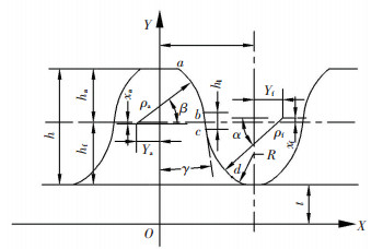 图 1 柔轮齿廓模型 Figure 1 Tooth profile of flexspline
 柔轮凸圆弧ab段齿廓方程:
$\left\{ \begin{array}{l}{X_{ab}} = {\rho _{\rm{a}}}\cos \beta - {Y_{\rm{a}}},\\{Y_{ab}} = {\rho _{\rm{a}}}\sin \beta + {h_{\rm{f}}} + t/2 - {X_{\rm{a}}},\\{\beta _b} < \beta < {\beta _a}.\end{array} \right.$ (1)
柔轮直线bc段齿廓方程:
$\left\{ \begin{array}{l}{X_{bc}} = t,\\{Y_{bc}} = kt + b,\\{\rho _{\rm{a}}}\cos {\beta _b} - {Y_{\rm{a}}} < t < {\rm{ \mathsf{ π} }}m/2 + {Y_{\rm{f}}} - {\rho _{\rm{f}}}\cos {\alpha _c}.\end{array} \right.$ (2)
柔轮凹圆弧cd段齿廓方程:
$\left\{ \begin{array}{l}{X_{cd}} = {\rm{ \mathsf{ π} }}m/2 + {Y_{\rm{f}}} - {\rho _{\rm{f}}}\cos \alpha ,\\{Y_{cd}} = {X_{\rm{f}}} + {h_{\rm{f}}} + t/2 - {\rho _{\rm{f}}}\sin \alpha ,\\{\alpha _c} < \alpha < {\alpha _d}.\end{array} \right.$ (3)
由于直线部分与凸圆弧和凹圆弧分别相切,可得以下约束条件:
$\left\{ \begin{array}{l}{\alpha _c} = {\rm{ \mathsf{ π} }} + {\beta _b},\\k = - \cot {\beta _b},\\k\left( {{\rho _{\rm{a}}}\cos {\beta _b} - {Y_{\rm{a}}}} \right) + b = {\rho _{\rm{a}}}\sin {\beta _b} + {h_{\rm{f}}} + t/2 - {X_{\rm{a}}},\\k\left( {{\rm{ \mathsf{ π} }}m/2 + {Y_{\rm{f}}} - {\rho _{\rm{f}}}\cos {\alpha _c}} \right) + b = {X_{\rm{f}}} + {h_{\rm{f}}} + \\\;\;\;\;\;\;\;t/2 - {\rho _{\rm{f}}}\sin {\alpha _c}.\end{array} \right.$ (4)
1.2 共轭齿廓坐标系建立不妨设波发生器与定坐标系(XOY)固连,波发生器长轴方向设为Y;柔轮与动坐标系(X1O1Y1)固连,柔轮齿对称线方向设为Y1;刚轮与动坐标系(X2O2Y2)固连,齿槽对称轴方向设为Y2.三个坐标系的相互关系如图 2所示.
Figure 2
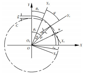 图 2 共轭区域坐标系 Figure 2 Conjugate regional coordinates
 图 2中,θ1是柔轮的转角,θ2是刚轮的转角,η是柔轮与刚轮的转角之差,φ是Y1轴与Y2轴之间的夹角,μ是Y1轴相对于矢径ρ转过的角度,W0是柔轮在径向的最大变形量,u是柔轮径向上的变形位移.原始曲线的等距曲线极坐标方程[12]为
$\rho \left( \theta \right) = {r_{\rm{m}}} + \omega \left( \theta \right).$
式中:ρ(θ)是C曲线等距曲线极半径,ω(θ)为中线上的点在柔轮发生径向变形后的位移,θ为柔轮未变形处的转角,rm为柔轮变形前的中线半径.
1.3 刚轮齿廓方程在柔轮发生径向和切向变形时,以中线不伸长为前提,柔轮的对称线会以矢径ρ为基准旋转一个角度μ,因为角度极小,故做如下简化:
$\mu = \mu \left( \theta \right) = \arctan \left| {\frac{{\rho '}}{\rho }} \right| = \arctan \frac{{\rho '}}{{{r_{\rm{m}}} + \omega }} \approx \frac{1}{{{r_{\rm{m}}}}}\frac{{{\rm{d}}\omega }}{{{\rm{d}}\theta }},$
其中ρ′为ρ对θ的导数.
根据谐波传动包络理论[13]求得刚轮齿廓的公式如下:
$\left\{ \begin{array}{l}{X_2}\left( {u,\theta } \right) = {X_1}\cos \varphi + {Y_1}\sin \varphi + \rho \sin \eta ,\\{Y_2}\left( {u,\theta } \right) = - {X_1}\sin \varphi + {Y_1}\cos \varphi + \rho \sin \eta ,\\\frac{{\partial {X_2}}}{{\partial u}} \cdot \frac{{\partial {Y_2}}}{{\partial \theta }} - \frac{{\partial {X_2}}}{{\partial \theta }} \cdot \frac{{\partial {Y_2}}}{{\partial u}} = 0.\end{array} \right.$ (5)
将式(1)代入式(5)中求出与柔轮凸齿廓共轭的刚轮齿廓:
$\left\{ \begin{array}{l}{X_2} = \left( {{\rho _{\rm{a}}}\cos \beta + {X_{ab}}} \right)\cos \varphi + \left( {{\rho _{\rm{a}}}\sin \beta + } \right.\\\;\;\;\;\;\;\;\;\;\left. {{Y_{ab}}} \right)\sin \varphi + \left( {{r_{\rm{m}}} + \omega \cos \theta } \right)\sin \eta ,\\{Y_2} = - \left( {{\rho _{\rm{a}}}\cos \beta + {X_{ab}}} \right)\sin \varphi + \\\;\;\;\;\;\;\left( {{\rho _{\rm{a}}}\sin \beta + {Y_{ab}}} \right)\cos \varphi + \left( {{r_{\rm{m}}} + \omega \cos \theta } \right)\cos \eta ,\\\left( {{X_{ab}}\sin \beta - {Y_{ab}}\cos \beta } \right)\left( {\frac{2}{{{z_2}}} - \frac{{5\omega }}{{{r_{\rm{m}}}}}} \right)\cos 2\theta + \\\;\;\;\;\;\;\;\sin \left( {\varphi - \beta - \eta } \right)\left( { - 2\omega \sin 2\theta } \right) - \\\;\;\;\;\;\;\;\rho \cos \left( {\varphi - \beta - \eta } \right)\left( {\frac{2}{{{z_2}}} - \frac{\omega }{{{r_{\rm{m}}}}}\cos 2\theta } \right) = 0.\end{array} \right.$ (6)
将式(2)代入式(5)中求出与柔轮直线段齿廓共轭的刚轮齿廓:
$\left\{ \begin{array}{l}{X_2} = t\cos \varphi + \left( {kt + b} \right)\sin \varphi + \left( {{r_{\rm{m}}} + \omega \cos \theta } \right)\sin \eta ,\\{Y_2} = - t\sin \varphi + \left( {kt + b} \right)\cos \varphi + \left( {{r_{\rm{m}}} + \omega \cos \theta } \right)\cos \eta .\end{array} \right.$ (7)
将式(3)代入式(5)中求出与柔轮凹齿廓共轭的刚轮齿廓:
$\left\{ \begin{array}{l}{X_2} = \left( {{X_{cd}} - {\rho _{\rm{f}}}\cos \alpha } \right)\cos \varphi + \\\;\;\;\;\;\;\;\;\left( {{Y_{cd}} - {\rho _{\rm{f}}}\sin \alpha } \right)\sin \varphi + \\\;\;\;\;\;\;\;\;\left( {{r_{\rm{m}}} - \omega \cos \theta } \right)\sin \eta ,\\{Y_2} = - \left( {{X_{cd}} - {\rho _{\rm{f}}}\cos \alpha } \right)\sin \varphi + \\\;\;\;\;\;\;\;\;\left( {{Y_{cd}} - {\rho _{\rm{f}}}\sin \alpha } \right)\cos \varphi + \\\;\;\;\;\;\;\;\;\left( {{r_{\rm{m}}} + \omega \cos \theta } \right)\cos \eta ,\\\left( {{X_{cd}}\sin \alpha - {Y_{cd}}\cos \alpha } \right)\left( {\frac{2}{{{z_2}}} - \frac{\omega }{{{r_{\rm{m}}}}}\cos 2\theta } \right) + \\\;\;\;\;\;\;\;\sin \left( {\varphi - \alpha - \eta } \right)\left( { - 2\omega \sin 2\theta } \right) - \\\;\;\;\;\;\;\;\rho \sin \left( {\varphi - \alpha - \eta } \right)\left( {\frac{2}{{{z_2}}} - \frac{\omega }{{{r_{\rm{m}}}}}\cos 2\theta } \right) = 0.\end{array} \right.$ (8)
具体设计过程可参照文献[14].
2 运动和受力分析 2.1 啮合速度和曲率半径柔轮轮齿的运动可分解为柔轮自身绕轴转动和柔轮中线的变形运动两部分,如图 3所示.柔轮上接触点K的运动速度可等效为刚体转动的牵连速度和弹性变形运动的相对速度的合成.
Figure 3
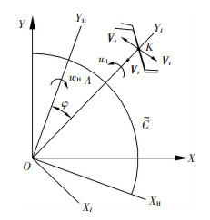 图 3 速度求解图 Figure 3 Velocity diagram
 图 3中,
${{\vec V}_K} = {{\vec V}_{\rm{e}}} + {{\vec V}_{\rm{r}}} + {{\vec V}_{\rm{t}}}.$
式中:Ve为啮合点K的牵连速度;Vr为啮合点的径向弹性变形速度;Vt为啮合点的切向变形速度.
当刚轮固定不动时,VK就是啮合点相对运动速度,取其沿齿廓切向的分量即为润滑计算时的表面速度.
柔轮与刚轮可以简化为半径分别为R1、R2的圆柱体滚子的内接触,R1、R2分别为柔轮、刚轮在啮合点的曲率半径.对于处于共轭啮合状态的双圆弧谐波减速器,啮合点的曲率半径R1为ρ1a,R2为ρ2f,综合曲率半径R为R2R1/(R2-R1).
2.2 柔轮载荷分析柔轮齿上的受载情况十分复杂,受到多种因素的影响,目前主要根据实验来得到啮合力的分布情况. 图 4为实验近似曲线[16],φ1为对称轴CC′和波发生器长轴AA′的夹角;φ2、φ3为啮合区,双圆弧齿廓一般根据实验近似取φ2=φ3=40°;qt为切向载荷;qr为径向载荷;α1为压力角.
Figure 4
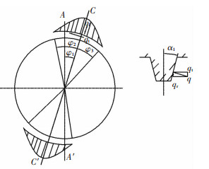 图 4 柔轮载荷分布图 Figure 4 The flexible wheel load distribution diagram
 如果柔轮受到的转矩为T,则
$T = 4\int_{{\varphi _1}}^{{\varphi _2}} {b{{\left( {d/2} \right)}^2}{q_{{\rm{tmax}}}}\cos \left[ {{\rm{ \mathsf{ π} }}\left( {\varphi - {\varphi _1}} \right)/\left( {2{\varphi _2}} \right)} \right]{\rm{d}}\varphi } ,$
于是,切向最大载荷qtmax为πT/(2φ2d2b),其中b为柔轮齿圈宽度;d为节圆直径.
为求出每个轮齿上的力,需对啮合区进行分段积分.假设一个齿距的两端对应的角度分别为φk、φk+1,作用在每个齿上的切向力为
${f_{\rm{t}}} = \int_{{\varphi _k}}^{{\varphi _{k + 1}}} {b\left( {d/2} \right){q_{{\rm{tmax}}}}\cos \left[ {{\rm{ \mathsf{ π} }}\left( {\varphi - {\varphi _1}} \right)/\left( {2{\varphi _2}} \right)} \right]{\rm{d}}\varphi } ,$
法向力fr为ft·tan α1.
3 混合润滑模型设卷吸速度方向为y方向,则谐波传动齿轮共轭啮合区的Reynolds方程为
$\begin{array}{l}\frac{\partial }{{\partial x}}\left( {\frac{\rho }{{12{\eta ^ * }}}{h^3}\frac{{\partial p}}{{\partial x}}} \right) + \frac{\partial }{{\partial y}}\left( {\frac{\rho }{{12{\eta ^ * }}}{h^3}\frac{{\partial p}}{{\partial y}}} \right) = \\U\frac{{\partial \left( {\rho h} \right)}}{{\partial x}} + \frac{{\partial \left( {\rho h} \right)}}{{\partial t}}.\end{array}$ (9)
式中:p为油膜压力;h为油膜厚度;ρ为润滑剂密度;U为卷吸速率;η*为润滑剂的有效黏度.
考虑润滑剂非牛顿润滑行为的剪切力为
$\frac{1}{{{\eta ^ * }}} = \frac{1}{\eta }\frac{{{\tau _0}}}{{{\tau _1}}}\sinh \left( {\frac{{{\tau _1}}}{{{\tau _0}}}} \right).$ (10)
式中:η表示润滑剂黏度,τ0表示参考剪应力,τ1表示作用于下表面的剪应力.
膜厚方程:
$\begin{array}{l}h = {h_0}\left( t \right) + 0.5{x^2}/R + {\delta _1}\left( {x,y,t} \right) + {\delta _2}\left( {x,y,t} \right) + \\\;\;\;\;\;V\left( {x,y,t} \right).\end{array}$ (11)
式中:h0(t)表示名义膜厚值;0.5x2/R表示柔轮与刚轮接触表面的初始间隙;δ1、δ2表示原始粗糙度幅值;V表示压力引起的表面弹性变形,有
$V\left( {x,y,t} \right) = \frac{2}{{\mathsf{ π}E'}}\iint\limits_\mathit{\Omega } {\frac{{{p_{\text{c}}}\left( {\xi ,\zeta } \right)}}{{\sqrt {{{\left( {x - \xi } \right)}^2} + {{\left( {y - \zeta } \right)}^2}} }}{\text{d}}\xi {\text{d}}\zeta }.$ (12)
式中,E′为综合弹性模量,Pc(ξ, ζ)为求解域内的压力.
黏压方程:
$\eta = {\eta _0}\exp \left\{ {\left( {\ln {\eta _0} + 9.67} \right)\left[ {{{\left( {1 + 5.1 \times {{10}^{ - 9}}p} \right)}^z} - 1} \right]} \right\},$ (13)
式中η0为大气压下(p=0)的黏度.
黏温方程:
$\lg \left( {\lg \left( {\eta + 0.6} \right)} \right) = b + m\lg T,$ (14)
式中,T表示温度;b、m为常数.
密压方程:
$\rho = {\rho _0}\left( {1 + \frac{{0.6 \times {{10}^{ - 9}}p}}{{1 + 1.7 \times {{10}^{ - 9}}p}}} \right),$ (15)
式中ρ0为大气压下(p=0)润滑剂的密度.
载荷平衡方程:
${f_{\text{r}}} = \iint\limits_\Omega {p\left( {x,y,t} \right){\text{d}}x{\text{d}}y}.$ (16)
以上式(9)~(16)中,润滑油黏度、弹性变形和密度都是压力的函数,将其与Reynolds方程合并为一个微分方程组,用复合迭代法[17-19]求解.为了减少计算量,需要将微分方程组离散化,通过二阶中心差分方程左边两项,再通过一阶向后差分方程右边两项来实现.用最初的压力值计算出弹性变形原始值,根据膜厚方程,用代入的初始间隙求出初始膜厚,接着再将其代入Reynolds方程中求出全部节点的压力.以此压力值作为新的压力代入方程求出新的弹性变形和膜厚,在下一步迭代中又重新获得压力分布,重复以上过程,直到压力
4 结果与讨论 4.1 基本参数柔轮齿廓参数如表 1所示.
表 1
0.5 0.45 0.525 0.45 8.175 0.975
ρa/mm ρf/mm Xa/mm Ya/mm Xf/mm Yf/mm
0.574 0.654 0 0.196 0.036 0.253
表 1 柔轮齿形参数 Table 1 Flexible wheel tooth profile parameters
根据包络法拟合出的共轭刚轮齿廓相关参数为:凸圆弧齿廓半径ρa为0.62 mm,凹圆弧齿廓半径ρf为0.588 2 mm.其余润滑基本参数如下:柔轮齿数z1为200,刚轮齿数z2为202;模数m为0.5;传动比i为100;压力角α为20°;波发生器名义输入转速nH为3 000 r/min,输出转矩T为650 N·m;柔轮材料密度7.83×10⁻³ g/mm3,弹性模量201 GPa,泊松比0.3;刚轮材料密度7.81×10⁻³g/mm3,弹性模量201 GPa,泊松比0.3;柔轮和刚轮的表面粗糙度值采用BRUKER公司的Contour GT-K光学轮廓仪实测得到,如图 5所示,其表面均方根分别为0.347 2和0.351 5 μm;边界摩擦系数为0.15.
Figure 5
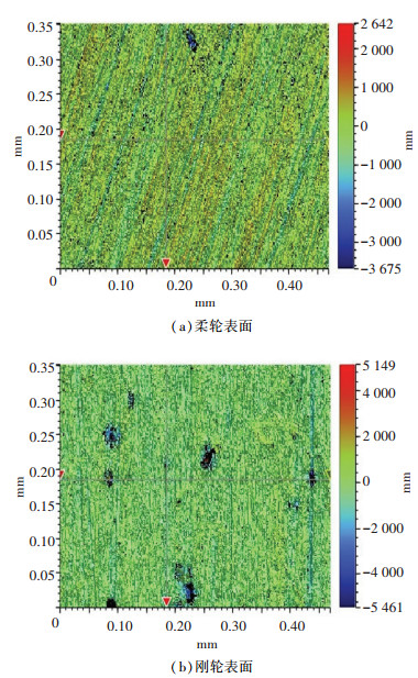 图 5 柔轮与刚轮表面 Figure 5 The surface of flexible wheel and rigid wheel
 选用两组润滑剂作为对比,第一组为特高级黏度指数润滑剂,它具有黏温曲线变化平缓的特点,其黏度特性如下:在40 ℃时的黏度为105.5 cSt,在100 ℃时的黏度为27.8 cSt,密度为0.88 g/cm3,根据黏温公式算出b为0.78,m为-0.3.第二组为高黏度指数润滑剂,相较于特高级黏度指数润滑剂,其黏温曲线要更陡一些,对温度也更敏感,其黏度特性如下:在40 ℃时的黏度为220 cSt,在100 ℃时的黏度为19.3 cSt,密度为0.907 g/cm3,算出b为1.41,m为-0.65.
4.2 转速对润滑性能的影响在温度40 ℃时,共设计9组不同的转速,考察了不同转速下啮合区的润滑性能,分析得到了接触区的摩擦因数f,膜厚比λ,接触载荷比Wc和接触面积比Ac等润滑参数,如图 6~8所示.
Figure 6
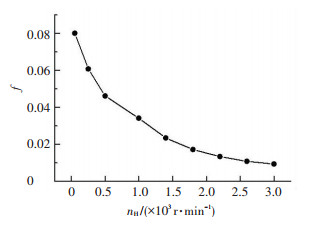 图 6 摩擦系数随转速的变化 Figure 6 The coefficient of friction changes with the rotation speed
 Figure 7
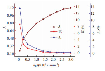 图 7 主要润滑参数随转速的变化 Figure 7 The main lubrication parameters change with the rotational speed
 Figure 8
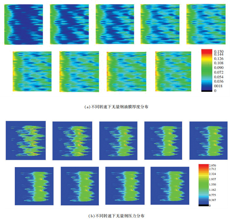 图 8 不同转速下油膜厚度和压力云图 Figure 8 Film thickness and pressure cloud diagram at different speeds
 由图 6可知,接触区的摩擦因数随着转速的增加而逐渐减小,润滑性能逐渐提高.当转速为50 r/min时,此时的摩擦因数为0.080 1;当转速达到2 200 r/min时,此时的摩擦因数为0.013 4,同比减小了83.3%,接触状况得到大幅改善.
由图 7可以看出,接触载荷比和接触面积比都随着转速的升高而减小,并且当转速大于2 200 r/min时,减小的速度明显变缓.当转速由50 r/min上升到2 200 r/min时,膜厚比由0.2增加到1,接触区由边界润滑转变为混合润滑,此时接触载荷比Wc为0.11%,接触面积比Ac为0.36%,较50 r/min时Wc为8.64%,Ac为13.65%分别减小了98.7%和97.4%,润滑性能得到改善.
从图 8也可看出,随着转速增大,粗糙峰接触面积迅速减小,油膜越来越厚,接触区的压力也随着降低.结合图 7可知,当转速大于2 200 r/min时,接触区几乎被油膜覆盖,Wc和Ac趋于最低值.因此,在较低转速下(小于2 200 r/min),转速对润滑性能的影响较为明显.
对比文献[7]和文献[20]中的实验数据可以看出,转速越高,接触区的润滑性能越好,谐波减速器的寿命越高,对柔轮越有利,与本文结果基本相同,证明了本文模型的正确性.
4.3 温度对润滑性能的影响保持转速与载荷等其他参数不变的情况下,改变两组润滑剂的温度来研究温度对啮合区润滑性能的影响,得到的结果如图 9~11所示.
Figure 9
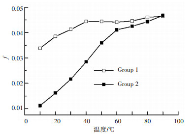 图 9 摩擦系数随温度的变化 Figure 9 The coefficient of friction changes with temperaturec
 Figure 10
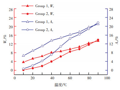 图 10 载荷比和面积比随温度的变化 Figure 10 The contact load ratio and contact area ratio change with temperature
 Figure 11
 图 11 不同温度下油膜厚度和压力云图 Figure 11 Film thickness and pressure cloud diagram at different temperatures
 从图 9可以看出,在温度为10 ℃时,使用第一组润滑剂的接触区摩擦因数为0.0338,大于第二组的0.0111.当温度上升到40 ℃时,第一、二组的摩擦因数分别升高到0.0443和0.0285,分别增加了31.1%和156.7%.随着温度继续升高,第一组润滑剂的摩擦因数不再有明显的变化.当温度达到60 ℃时,第二组润滑剂的摩擦因数为0.0411,相比10 ℃时增加了270.3%,相比40 ℃时增加了44.2%.当温度大于60 ℃时,两组的摩擦因数的升高都趋于平稳,并且越来越接近.
从图 10可知,随着温度升高,两组的接触载荷比和接触面积比都逐渐升高,并且趋势相似.取第一组来分析,在10 ℃时,其接触载荷比和接触面积比分别为3.69%和6.63%.在60 ℃时,接触载荷比和接触面积比分别为9.59%和16.15%,分别增加了159.9%和143.6%.当温度大于60 ℃时,上升趋于平缓,在90 ℃时,较60 ℃只分别增加了38.9%和30.1%,并且一、二两组之间的差距也在不断缩小.
如图 11所示,油膜厚度随着温度的升高而减小,微凸体接触面积逐渐变小,因油膜减小,压力逐渐增大.在温度大于60 ℃时,油膜厚度和压力变化不大,因此在温度小于60 ℃时,温度对润滑状态的作用较明显,合理地控制温度有利于油膜的形成.
5 结论1) 综合考虑共轭啮合区的宏观几何、真实表面粗糙度、接触载荷等因素,建立了柔轮与刚轮的混合润滑模型,定量分析了转速和温度对谐波减速器混合润滑特性的影响规律,揭示了齿轮副承载与润滑机理,为进一步研究谐波减速器加速寿命试验方法提供理论指导,为指导产品优化设计提供支撑.
2) 转速越高,平均油膜厚度和膜厚比越大,接触载荷比和接触面积比越小,润滑性能越好.当转速由50 r/min升高到2 200 r/min时,啮合区由边界润滑变为混合润滑,摩擦因数减小一半以上,接触载荷比和接触面积比减小90%以上.因此,将转速控制在2200 r/min以上有利于改善润滑状况.
3) 随着啮合区温度的升高,平均油膜厚度和膜厚比逐渐减小,接触载荷比和接触面积比逐渐增大,润滑状况逐渐变差.当温度由10 ℃升高到60 ℃时,摩擦因数提高了一倍以上,膜厚比迅速降低,接触载荷比和接触面积比升高一倍以上,润滑状况明显恶化.因此,需严格控制谐波减速器的工作温度在60 ℃以内.
参考文献
[1] 丰飞, 王炜, 唐丽娜, 等. 空间高精度谐波减速器的应用及其发展趋势[J]. 机械传动, 2014, 38(10): 98-107.
FENG Fei, WANG Wei, TANG Lina, et al. Application and development trends of the space harmonic reducer with high precision[J]. Mechanical transmission, 2014, 38(10): 98-107.
[2] 夏田, 江鹏, 马超, 等. 谐波减速器柔轮摩擦磨损及失效机理研究进展[J]. 机械传动, 2016, 40(1): 173-176.
XIA Tian, JIANG Peng, MA Chao, et al. Research advance of the failure mechanism and friction wear of flexible wheel of harmonic reducer[J]. Mechanical Transmission, 2016, 40(1): 173-176. DOI:10.16578/j.issn.1004.2539.2016.01.041
[3] Harmonic Driver Systems Inc. Support & Downloads[EB/OL]. [2016-11-20]. http://www.harmonicdrive.net.cn/DownList.aspx.
[4] 杨勇, 王家序, 周青华, 等. 双圆弧谐波齿轮传动柔轮齿廓参数的优化设计[J]. 四川大学学报(工程科学版), 2016, 48(1): 186-193.
YANG Yong, WANG Jiaxu, ZHOU Qinghua, et al. Optimization design for flexspline tooth profile parameters of double-circular-arc harmonic drives[J]. Journal of Sichuan University (Engineering Science Edition), 2016, 48(1): 186-193. DOI:10.15961/j.jsuese.2016.01,028
[5] 吴伟国, 于鹏飞, 侯月阳. 短筒柔轮谐波齿轮传动新设计新工艺与实验[J]. 哈尔滨工业大学学报, 2014, 46(1): 40-46.
WU Weiguo, YU Pengfei, HOU Yueyang. New design, new process of harmonic drive with short flexspline and its experiment[J]. Journal of Harbin Institute of Technology, 2014, 46(1): 40-46.
[6] 吴继强, 王家序, 蒲伟, 等. 齿廓形状对谐波齿轮共轭啮合区润滑性的影响[J]. 华中科技大学学报(自然科学版), 2017, 45(4): 29-33.
WU Jiqiang, WANG Jiaxu, PU Wei, et al. Effect of tooth profile on lubrication performance at the conjugate meshing domain of harmonic gear[J]. Journal of Huazhong Univ. of Sci. & Tech. (Natural Science Edition), 2017, 45(4): 29-33. DOI:10.13245/j.hust.170406
[7] SCHAFER I, BOURLIER P, HANTSCHACK F, et al. Space lubrication and performance of harmonic drive gears[C]// Proceedings of the 11th European Space Mechanisms and Tribology Symposium, ESMATS 2005. Lucerne: European Space Agency, 2005: 65-72.
[8] OSTAPSKI W. Analysis of the stress state in the harmonic drive generator-flexspline system in relation to selected structural parameters and manufacturing deviations[J]. Bulletin of the Polish Academy of Sciences Technical Sciences, 2010, 58(4): 683-698. DOI:10.2478/v10175-010-0073-8
[9] OSTAPSKI W, MUKHA I. Stress state analysis of harmonic drive elements by FEM[J]. Bullet in of the Polish Academy of Sciences Technical Sciences, 2007, 55(1): 115-123.
[10] 李俊阳, 王家序, 范凯杰, 等. 谐波减速器黏着磨损失效加速寿命模型研究[J]. 摩擦学学报, 2016, 36(3): 297-303.
LI Junyang, WANG Jiaxu, FAN Kaijie, et al. Accelerated life model for harmonic drive under adhesive wear[J]. Tribology, 2016, 36(3): 297-303. DOI:10.16078/j.tribology.2016.03.005
[11] 严锋, 杨为, 段成财, 等. 谐波减速器柔轮的疲劳寿命分析[J]. 现代制造工程, 2013(10): 17-19.
YAN Feng, YANG Wei, DUAN Chengcai, et al. Fatigue life analysis of harmonic reducer flexspline[J]. Modern Manufacturing Engineering, 2013(10): 17-19. DOI:10.3969/j.issn.1671-3133.2013.10.004
[12] CHEN X, LIU Y, XING J, et al. The parametric design of double-circular-arc tooth profile and its influence on the functional backlash of harmonic drive[J]. Mechanism & Machine Theory, 2014, 73(2): 1-24.
[13] 林森. 双圆弧短筒谐波减速器设计[D]. 南京: 南京信息工程大学, 2016.
LIN Sen. Design of short harmonic drive with double-circular-arc tooth profile[D]. Naning: Nanjing University of Information Engineering, 2016. http://cdmd.cnki.com.cn/Article/CDMD-10300-1016198045.htm
[14] 辛洪兵. 双圆弧谐波齿轮传动基本齿廓设计[J]. 中国机械工程, 2011, 22(6): 656-662.
XIN Hongbing. Design for basic rack of harmonic drive with double-circular-arc tooth profile[J]. Chinese Mechanical Engineering, 2011, 22(6): 656-662.
[15] 鞠永青, 孔宪梅, 胡元中. 谐波齿轮传动轮齿润滑研究[J]. 机械传动, 1992(3): 29-34.
JU Yongqing, KONG Xianmei, HU Yuanzhong. The research of harmonic gear wheel gear lubrication.[J]. MechanicalTransmission, 1992(3): 29-34.
[16] KAYABASI O, ERZINCANLI F. Shape optimization of tooth profile of a flexspline for a harmonic drive by finite element modelling[J]. Materials & Design, 2007, 28(2): 441-447. DOI:10.1016/J.MATDES.2005.09.009
[17] ZHU D, HU Y Z. The study of transition from full film elastohydrodynamic to mixed and boundary lubrication[C]// Proceedings of the 1999, STLE/ASME HS Cheng Tribology Surveillance. Park Ridge: STLE, 1999: 150-156.
[18] HU Y Z, ZHU D. A full numerical solution to the mixed lubrication in point contacts[J]. Journal of Tribology, 2000, 122(1): 1-9. DOI:10.1115/1.555322
[19] ZHU D, WANG Q J, REN N. Pitting life prediction based on a 3D line contact mixed EHL analysis and subsurface von mises stress calculation[J]. Journal of Tribology, 2009, 131(4): 178-179. DOI:10.1115/1.3195040
[20] ZHANG C, WANG S P, WANG Z M, et al. An accelerated life test model for harmonic drives under a segmental stress history and its parameter optimization[J]. Chinese Journal of Aeronautics, 2015, 28(6): 1758-1765. DOI:10.1016/j.cja.2015.07.003
