Wenfeng Bian1 , Weiyi Shao1and Baoming Wang2
(1.Department of Civil Engineering,Harbin Institute of Technology,Weihai 264209,Shandong,China;2. Weihai Guangwei Composities Co., Ltd.,Weihai 264209,Shandong,China)
Abstract:
Carbon Fiber Reinforced Polymer (CFRP) has such characteristics as light weight, high strength and corrosion resistance, so it is suitable for corrosive environment and large-span structures. This study investigated the stability of CFRP slender column, whose slenderness is greater than Euler's critical load. The columns in this study were formed by a two-step process and the fiber direction was along the same direction of column axis. Firstly, we obtained the basic mechanical properties of the material by tensile experiment. Then, we studied the critical force of 10 CFRP columns with different lengths and widths by axial compression test. Finally, by comparing Euler's formula with the modified Euler formula and combining with existing literature and experimental result of this paper, we proposed a modified Perry formula which could well predict the critical force of unidirectional CFRP extruded column and could be used for CFRP extruded column research and engineering design.
Key words: unidirectional CFRP slender column critical force stability factor modified Perry formula
DOI:10.11916/j.issn.1005-9113.18058
Clc Number:TN957.51
Fund:
Wenfeng Bian, Weiyi Shao, Baoming Wang. Analysis on Critical Force of Unidirectional CFRP Slender Column[J]. Journal of Harbin Institute of Technology (New Series), 2019, 26(4): 25-31. DOI: 10.11916/j.issn.1005-9113.18058.

Fund Sponsored by the Shandong Provincial Natural Science Foundation, China (Grant No. ZR2018MA029) Corresponding author Wenfeng Bian, E-mail: bianwf@163.com Article history Received: 2018-05-24
Contents Abstract Full text Figures/Tables PDF
Analysis on Critical Force of Unidirectional CFRP Slender Column
Wenfeng Bian1

 , Weiyi Shao1, Baoming Wang2
 1. Department of Civil Engineering, Harbin Institute of Technology, Weihai 264209, Shandong, China;
2. Weihai Guangwei Composities Co., Ltd., Weihai 264209, Shandong, China
Received: 2018-05-24
Sponsored by the Shandong Provincial Natural Science Foundation, China (Grant No. ZR2018MA029)
Corresponding author: Wenfeng Bian, E-mail: bianwf@163.com
Abstract: Carbon Fiber Reinforced Polymer (CFRP) has such characteristics as light weight, high strength and corrosion resistance, so it is suitable for corrosive environment and large-span structures. This study investigated the stability of CFRP slender column, whose slenderness is greater than Euler's critical load. The columns in this study were formed by a two-step process and the fiber direction was along the same direction of column axis. Firstly, we obtained the basic mechanical properties of the material by tensile experiment. Then, we studied the critical force of 10 CFRP columns with different lengths and widths by axial compression test. Finally, by comparing Euler's formula with the modified Euler formula and combining with existing literature and experimental result of this paper, we proposed a modified Perry formula which could well predict the critical force of unidirectional CFRP extruded column and could be used for CFRP extruded column research and engineering design.
Keywords: unidirectional CFRP slender column critical force stability factor modified Perry formula
1 Introduction The macroscopic mechanical properties of CFRP are determined by the properties of fiber and resin. CFRP has many advantages such as high specific strength, high specific stiffness, anti-fatigue, vibration reduction, high temperature resistance, and designability, so it has been widely used in many fields such as aerospace.
Qian Peng et al.[1] did axial stress test on three sets of CFRP tubes, analyzed causes of different failure situations and proposed theoretical formulae of four different failure modes. Zhang Liangquan et al.[2-4] used filament winding process to make two sizes of orthogonal symmetric layered CFRP round columns and did compression experiment on them. The result showed that compression failure is a linear elastic process. The main phenomenon is fiber breakage and matrix cracking and the hoop strain is much smaller than the axial strain. Nan Bo et al. [5] used pultruded CFRP tubes in axial compression test to analyze their critical forces and failure form, then compared the results with that of finite element model (considering the Hashin criterion and the initial defect). They focused on the influence of slenderness ration on stability factor and got a quantitative relationship. Xue Xiaomin et al.[6] tested the mechanical properties and stability of glass fiber reinforced polymer (GFRP) and compared test results with Euler formula, Perry formula, and a modified Perry formula proposed in the paper. It is found that Euler formula is not suitable for composite components, but the modified Perry formula can predict better the result. Hou Wei et al. [7] did axial compression tests on 50 GFRP round and L-section columns with different slenderness, analyzed their deformation failure, and proposed a stability factor formula. Experimental result is that GFRP shows linear elasticity before instability. Instability failure is extreme point failure and the stability factor formula calculation is closed to experimental result. Correia et al. [8] discussed the buckling behavior and failure of hybrid fiber-reduced polymer pultruded short columns. The strength and stiffness can be increased by adding carbon fiber into GFRP materials. They used orthotropic plate theory based solution to predict the critical buckling loads and found both numerical and analytical results are close to the experimental data. Results obtained show that with the introduction of CFRP sheets in the flanges of the GFRP profile, the critical load, ultimate load and axial stiffness considerably increase. Sivakumar, Kakogiannis et al.[9-10] applied finite element analysis and axial dynamic compression experiment on pultruded GFRP column. They tested three different loading conditions and two different end failure modes and studied their influence on compressive bearing capacity and failure mode. P Qiao et al. [11] analyzed local buckling of discrete laminated FRP plates, proposed analytical method under different boundary conditions and elastic restraints, and obtained simplified expressions for predictions of plate buckling stress resultants. Explicit expressions for the coefficients of restraint for I- and box-sections are given. It is shown that actual cases lie between simply supported and fully restrained (clamped) conditions. The theoretical predictions show good agreement with experimental data and finite-element eigenvalue analyses for local buckling of FRP columns. P Qiao et al. [12] analyzed local buckling of rectangular FRP plates, proposed a variational formula of the Ritz method which satisfy all the restrained boundary conditions, and the explicit solution of plate local buckling coefficients is obtained. The explicit formulas for local buckling strength of orthotropic plates are simplified to the cases of isotropic plates. The theoretical predictions are in good agreement with experimental results. The present explicit formulation can be applied to determine local buckling capacities of composite plates with elastic restraints along the unloaded edges and can be further used to predict the local buckling strength of FRP shapes. A Lane et al. [13] did an experimental investigation concerning the buckling behavior of pultruded fiber-reinforced plastic (PFRP) columns. Test were performed on wide-flange pultruded members across a range of lengths where local, global, and combined buckling modes were expected. Great care was taken during the experiments to ensure that the applied load was truly concentric, so that any interaction would be due to column imperfections alone. The experimental results will be used in future to prepare guidance for code writers and designers. P Qiao et al. [14] did finite-element analyses for local buckling of FRP wide-flange columns. By considering an interpolation function of the RF buckling, a variational formulation of the Ritz method is used to establish an eigenvalue problem and a flange critical local buckling coefficient is determined. The explicit predictions are in good agreements with experimental data, and can facilitate the local buckling analysis and design of open FRP structural profiles (e.g., I and channel shapes). N K Hassan et al.[15] investigated on the buckling behavior of concentrically loaded thin-walled pultruded fiber reinforced polymer (PFRP) composite columns. Both open- and closed-web columns were evaluated. Finite element (FE) analysis and theoretical predictions are presented and correlated with experimental data. Good agreement between theoretical, analytical, and experimental results was achieved. The paper also presents design guidelines to determine the bending stiffness and the critical buckling load for pultruded composite columns. In addition, a discussion on the axial strength of unidirectional PFRP columns and identification of different modes of failure are presented. L P Kollar et al.[16] did a local buckling analysis of FRP composite open and closed thin-walled section of box-, I-, C-, Z-, and L-members. These simple, explicit formulas contain the width and the bending stiffness of each wall segment. Analysis shows that this method is very practical.
At present, most researches on critical force of composite columns are about GFRP, there are few studies on CFRP columns and evenfewer studies on CFRP pultruded by two-step process. Thus in this paper we studied CFRP slender column pultruded by two-step process and proposed an empirical formula suitable for this kind of materials.
2 Mechanical Properties Experiment of CFRP Material The critical force of the column is the minimum pressure at which the column maintains a slight bending balance. In stability study of columns, the mechanical properties such as bending elastic modulus and ratio limit of the material are required. Our group has been engaged in research of different FRP for a long time. The properties of some CFRP are listed in Table 1.
表 1
CCF300 142 130 120
T700 126 120 110
M40J 230 220 200
Table 1 Test modulus of some common epoxy-based CFRP
Table 1 shows that the tensile modulus, compression modulus, and flexural modulus of the CFRP material pultruded by two-step process are quite the same. Therefore, the mechanical properties of the unidirectional CFRP material were measured by a tensile test. It is considered that the tensile modulus is the same as the compression modulus.
2.1 Test Piece Preparation and Testing The experimental material is T300 carbon fiber wire and epoxy resin matrix provided by Weihai Guangwei Composite Material Co., Ltd. Its resin content is 33%. The main material properties are shown in Table 2.
表 2
Carbon fiber (T300) 3 800 235 1.8
Epoxy resin 85 3 1.1
Table 2 Material properties
The test piece underwent a two-step pressure forming process: firstly, we dried a single layer of continuous carbon fiber impregnated with resin glue to make it a dry or a slightly sticky prepreg sheet; then, we laid multi-layers and placed them in an autoclave to be molded with heat and pressure according to design requirements. This process can ensure the stable dimensions and excellent performance of the material.
Test piece size design according to GB/T1447-2005 is shown in Fig. 1.
Fig.1
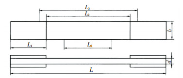 Fig.1 Schematic design of the test piece
 Total length L=250 mm, gauge segment length L0=100 mm, distance between the reinforcing plates L2 =150 mm, width of the test piece is 20 mm and thickness is 2 mm. Five test pieces were produced, as shown in Fig. 2.
Fig.2
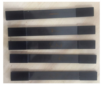 Fig.2 Standard CFRP test pieces
 The tensile test was performed on a WDW-100 electronic universal experimental machine and the strain was measured by an extensometer, as shown in Fig. 3. Experimental load includes preload and official load according to the regulations of GB/T 1447-2005.
Fig.3
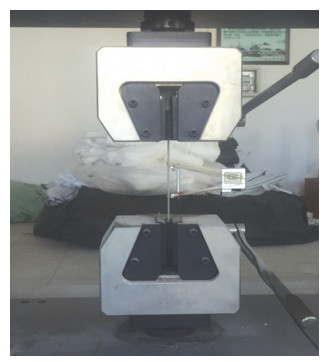 Fig.3 CFRP tensile test
 2.2 Analysis of Tensile Test Results The stress-strain curve measured by experiment is shown in Fig. 4.
Fig.4
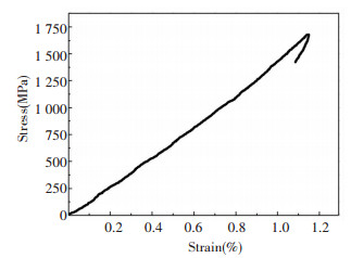 Fig.4 Stress-strain curve
 The curve shows that the stress and strain of CFRP materials manifest obvious linear elasticity and the material failure occurs suddenly (brittle failure). The average of CFRP material elastic modulus measured in experiment is 131.1 GPa and the ratio limit σp is 1 700 MPa.
According to the composite material mixing rate model, the basic parameters of each content in the material are brought into Eq.(1), then the theoretical prediction of the elastic modulus is
$E_{1}=E_{\mathrm{f}} v_{\mathrm{f}}+E_{\mathrm{m}} v_{\mathrm{m}}$ (1)
where Ef and Em are elastic modulus of fiber and matrix; vf and vm are volume content of fiber and matrix. Ef=235 GPa, Em=3 GPa, vf=55%, vm=45%, then E1=130.6 GPa.
The predicted theoretical values are in good agreement with the experimental data.
3 Critical Force Test of CFRP Slender Column 3.1 Test Overview The materials used to make columns and tensile test pieces are the same, and two sets of rectangular cross-section columns specimens were produced, whose cross-sectional dimensions are 20 mm×2 mm and 20 mm×1.2 mm, and whose lengths are 364, 309, 254, 199, 144 mm, respectively.
The test was realized on XL3410S multi-functional column stabilizing experimental device. In order to better perform the test, the upper and lower supports of the experimental device were both hinged and fixed, which could be freely combined. For short piece test, the base of the device can be lifted with thread lifting module, as shown in Fig. 5.
Fig.5
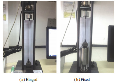 Fig.5 Loading device
 For each length dimension, three test pieces were prepared to ensure the accuracy of the test results and each test piece was tested three times. The average of nine test values was used as the final value of the critical force measured in experiment. The lengths of columns were also different on the raison of different boundary conditions such as fixed at one end and hinged at the other end, hinged at both ends and fixed at both ends.
3.2 Test Results and Analysis Two types of curves appeared during the loading test, as shown in Fig. 6. Solid line is the curve of the ideal state of the stability test. The load rises to a high level at first, and then drops back to Pcr. However, in the experiment, because of inevitable initial curvature, non-uniformality of the material, load eccentricity, etc., when the load was less than Pcr, the column also had a slight bending deformation; when close to Pcr, the bending deformation suddenly increased and lost stability, as shown by dotted line in Fig. 6. The critical force measured by the test is shown in Tables 3-5.
Fig.6
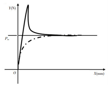 Fig.6 Curve of CFRP column stability test
 表 3
199×20×2 232 401 9.47 3.51
254×20×2 287 497 5.78 2.62
309×20×2 342 592 3.97 1.41
364×20×2 397 687 2.71 5.46
144×20×1.2 177 506 5.14 1.04
199×20×1.2 232 663 2.58 3.04
254×20×1.2 287 820 1.38 6.10
309×20×1.2 342 977 0.94 4.32
364×20×1.2 397 1 134 0.58 5.15
Table 3 Experimental critical force of hinge supports at both ends
表 4
364×20×2 369 447 6.45 6.30
309×20×2 314 381 9.46 2.82
254×20×2 259 314 13.44 1.73
199×20×2 204 247 22.50 4.96
364×20×1.2 369 760 1.87 4.42
309×20×1.2 314 646 2.46 2.31
254×20×1.2 259 533 4.16 7.30
199×20×1.2 204 420 7.73 5.44
144×20×1.2 149 307 15.06 3.02
Table 4 Experimental critical force of supports hinged at one end and fixed at the other end
表 5
364×20×2 334 289 13.24 1.45
309×20×2 279 241 19.83 3.59
254×20×2 224 193 30.41 3.04
364×20×1.2 334 491 4.74 5.30
309×20×1.2 279 410 7.45 7.50
254×20×1.2 224 329 10.82 5.86
199×20×1.2 169 248 22.80 4.91
144×20×1.2 114 168 49.25 7.12
Table 5 Experimental critical force of fixed supports at both ends
3.3 Column Critical Force Calculation The Euler formula for the stability analysis of slender column is shown as
$\sigma_{\mathrm{cr}}=\frac{\mathsf{π}^{2} E}{\lambda^{2}} \leqslant \sigma_{\mathrm{p}}$ (2)
The critical slenderness in Euler formula of CFRP used in this paper is 27.6. Compared with the slenderness of columns in Tables 3-5, all CFRP columns studied in this paper are large slenderness slender column and their critical force can be calculated by Euler formula for slender column stability analysis.
However, due to the anisotropy of the composite material, previous studies have found that there are errors when Euler formula is used to calculate the critical force of the slender column of composite materials, so Zureik [17] proposed a modified Euler formula that considers the shear deformation factors. For a column with any supports, the critical force of the column considering shear deformation can be expressed by the following formula:
$\sigma_{\mathrm{sh}}=\frac{\sigma_{\mathrm{er}}}{1+\frac{\sigma_{\mathrm{cr}} \beta}{G}}$ (3)
where G is the shear modulus of the material; the material in this paper is 4.7 GPa; β is the cross-section shear shape coefficient, for rectangular cross-section is 1.2.
However, the research results of Scott[18] show that the shear effect of composite columns has no obvious influence on stability, generally less than 5%. At present, the calculation method for the critical force of the composite column is not yet perfect and there is still no common calculation method. At the same time, the failure mode of the composite material is brittle failure, so the instability failure of the elastic phase should be mainly considered. Thus, this paper compares the experimental results by Euler's formula and that by the modified Euler's formula which considers the shear deformation correction. The results of the analysis are shown in Fig. 7.
Fig.7
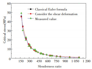 Fig.7 Experimental and theoretical critical force of CFRP columns
 It can be seen from the curves that the average error between the predicted Euler formula, the modified Euler formula, and the experimental result is not large, which is about 10%, but the comparison results show that partial column experimental critical forces are higher than the predicted values of Eqs.(2) and (3), and the critical forces of the other part of columns are lower than the predicted value of the two Euler formulas, which is unfavorable for the design. At the same time, although Euler's formula considering shear deformation improves prediction accuracy, it is very limited and only increases about 1%.
In practice, component with axial compression cannot avoid initial bending during manufacture, and initial eccentricity may occur during loading. These geometric defects will cause bending moments, thereby reducing the critical force. Based on this, this paper firstly proposed to fit the equivalent relative initial bending ε0, and then used the modified Perry formula[19] to calculate the critical force of the column, as shown in
$\varphi=\frac{1}{2 \lambda_{n}^{2}}\left[\left(1+\varepsilon_{0}+\lambda_{n}^{2}\right)-\right.\sqrt{\left(1+\varepsilon_{0}+\lambda_{n}^{2}\right)^{2}-4 \lambda_{n}^{2}}]$ (4)
where φ is the stability coefficient of the column; λn=
Referring to the technical specification of cold-formed thin-walled steel structures in China[20], the expression of initial relative eccentricity is taken as
$\varepsilon_{0}=a+b \lambda_{n}^{2}$ (5)
Combining the literature[18] with the experimental results, we get a=0.42, b=0.06. Substituting these values into Eq.(4), we have
$\begin{aligned} \varphi=& \frac{1}{2 \lambda_{n}^{2}}\left[\left(1.42+1.06 \lambda_{n}^{2}\right)-\right.\\ &\sqrt{\left(1.42+1.06 \lambda_{n}^{2}\right)^{2}-4 \lambda_{n}^{2}}] \end{aligned}$ (6)
Considering the safety of actual structure, a reduction factor of 0.85 is taken, so the modified Perry formula is given by Eq.(7):
$\sigma \leqslant \varphi_{{\rm c}} \varphi \sigma_{\mathrm{p}}$ (7)
The experimental results and the modified Perry formula are plotted in Fig. 8.
Fig.8
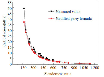 Fig.8 Comparison of predicted results by modified Perry formula with experimental results
 It can be seen from the curve that the modified Perry formula is close to the experimental results, and the prediction result is lower than the experimental results, which is conducive to the actual production design.This formula is suitable for unidirectional slender rectangular CFRP columns.
4 Conclusions 1) In tensile test, the CFRP columns showed a significant linear elasticity, and the failure occurred abruptly, which is brittle failure.
2) According to the axial compression test comparison of unidirectional CFRP columns with different slenderness, there are errors in critical forces between the experiment and Euler formula. The prediction of Euler formula is inaccurate. Considering shear deformation, the prediction accuracy could be improved, but influence is little.
3) By studying the experimental regularity and the experimental results, the modified Perry formula is proposed to improve the calculation precision of the critical force of unidirectional CFRP column. The formula can be used in practical engineering design and is suitable for unidirectional slender rectangular CFRP column. The formula ensures the accuracy and the calculation result is lower than the experimental value, which is conducive to design safety.
References
[1] Qian Peng, Ye Lieping, Weng Guanqun. Experimental study on axial force performance of CFRP tube. Industrial Architecture, 2004, 34(4): 11-14. (
 0)
0)[2] Zhang Liangquan, Li Hui, Ou Jinping. Experimental study and numerical simulation of the mechanical properties of fiber-wound CFRP tubes. China Civil Engineering Journal, 2009(8): 50-56. (
 0)
0)[3] Zhang Liangquan, Li Hui. Experimental study on mechanical properties of fiber-wound CFRP pipe. Industrial Construction, 2009, 39(8): 76-79. (
 0)
0)[4] Zhang Liangquan, Li Hui, Ou Jinping. Study on strength properties of fiber-wound CFRP circular tubes. Journal of Shenyang Jianzhu University Natural Science, 2010, 26(3): 409-415. (
 0)
0)[5] Nan Bo, Wu Yue, Sun Haotian. Axial compression performance of pultruded CFRP tube. Journal of Harbin Engineering University, 2015(6): 779-783. (
 0)
0)[6] Xue Xiaomin, Sun Qing, Wang Huchang, et al. Experimental study and theoretical study on the stability of compressed pipe fittings made of glass fiber reinforced epoxy resin composites. Engineering Mechanics, 2013, 30(9): 251-258. (
 0)
0)[7] Hou Wei, Zhang Xinghu, Feng Haichao. Stability performance of GFRP axial compression members. Journal of Building Materials, 2010, 13(4): 441-445. (
 0)
0)[8] Correia M M, Nunes F, Correia J R, et al. Buckling behavior and failure of hybrid fiber-reduced polymer pultruded short columns. Journal of Composites for Construction, 2013, 17(4): 463-475. DOI:10.1061/(ASCE)CC.1943-5614.0000339 (
 0)
0)[9] Palanivelu S, Paepegem W V, Degrieck J, et al. Parametric study of crushing parameters and failure patterns of pultruded composite tubes using cohesive elements and seam, Part Ⅰ: Central delamination and triggering modelling. Polymer Testing, 2010, 29(6): 729-741. DOI:10.1016/j.polymertesting.2010.05.010 (
 0)
0)[10] Palanivelu S, Paepegem W V, Degrieck J, et al. Parametric study of crushing parameters and failure patterns of pultruded composite tubes using cohesive elements and seam: Part Ⅱ - Multiple delaminations and initial geometric imperfections. Polymer Testing, 2010, 29(7): 803-814. DOI:10.1016/j.polymertesting.2010.07.005 (
 0)
0)[11] Qiao P, Davalos J F, Wang J. Local buckling of composite FRP shapes by discrete plate analysis. Journal of Structural Engineering, 2001, 127(3): 245-255. DOI:10.1061/(ASCE)0733-9445(2001)127:3(245) (
 0)
0)[12] Qiao P, Zou G. Local buckling of elastically restrained fiber-reinforced plastic plates and its application to box sections. Journal of Engineering Mechanics, 2002, 128(12): 1324-1330. DOI:10.1061/(ASCE)0733-9399(2002)128:12(1324) (
 0)
0)[13] Lane A, Mottram J T. Influence of modal coupling on the buckling of concentrically loaded pultruded fibre-reinforced plastic columns. Proceedings of the Institution of Mechanical Engineers Part L Journal of Materials Design & Applications, 2002, 216(2): 133-144. (
 0)
0)[14] Qiao P, Zou G. Local buckling of composite fiber-reinforced plastic wide-flange sections. Journal of Structural Engineering, 2003, 129(1): 125-129. DOI:10.1061/(ASCE)0733-9445(2003)129:1(125) (
 0)
0)[15] Hassan N K, Mosallam A S. Buckling and ultimate failure of thin-walled pultruded composite columns. Polymers & Polymer Composites, 2004(6): 469-481. (
 0)
0)[16] Kolla R L P. Local buckling of fiber reinforced plastic composite structural members with open and closed cross sections. Journal of Structural Engineering, 2005, 131(5): 853. DOI:10.1061/(ASCE)0733-9445(2005)131:5(853) (
 0)
0)[17] Zureick A. FRP pultruded structural shapes. Progress in Structural Engineering & Materials, 2010, 1(2): 143-149. (
 0)
0)[18] Zureick A H, Scott D W. Short-term behavior and design of fiber-reinforced polymeric slender members under axial compression. Journal of Composites for Construction, 1997, 1(4): 140-149. DOI:10.1061/(ASCE)1090-0268(1997)1:4(140) (
 0)
0)[19] Zhang Yaochun. Principles of Steel Structure Design. Beijing: Higher Education Press, 2011. (
 0)
0)[20] Hubei Provincial Planning Committee. Technical Specifications for Sold-Formed Shin-Walled Steel Structures. Beijing: China Planning Press, 1989. (
 0)
0)