许昶1,刘志明1,刘文飞2
(1.北京交通大学 机械与电子控制工程学院,北京 100044; 2.台州学院 航空工程学院,浙江 台州 317000)
摘要:
以碳纤维增强双马来酰亚胺树脂基复合材料平-折-平(FJF)胶接连接接头为对象,构造了圆弧段胶接梁单元,建立用于FJF胶接接头胶层应力分析的半解析模型,并与三维有限元模型胶层应力结果进行对比. 同时分析了胶层宽度和厚度对胶层应力的影响. 结果表明,利用半解析模型计算得出的胶层剥离应力和剪切应力分布与三维有限元模型获得的对应应力分布基本一致,搭接区端部胶层剥离应力和剪切应力相较于三维有限元模型计算结果的误差绝对值分别为5.4%和3.7%,有着较好的计算精度. 搭接区端部胶层剥离应力和剪切应力值在胶层宽度一定时随胶层厚度的增加而降低,在胶层厚度一定时随胶层宽度的增加而降低. 搭接区圆角胶层剥离应力和剪切应力值在胶层厚度一定时随胶层宽度的增加而降低,在胶层宽度一定时随胶层厚度的增加而增加. 该模型能够为碳纤维增强复合材料平-折-平胶接连接接头的应力分析提供一定的参考.
关键词: 碳纤维增强复合材料 FJF胶接连接接头 半解析模型 胶层应力分析 胶层宽度 胶层厚度
DOI:10.11918/201909221
分类号:TB331
文献标识码:A
基金项目:十三五国家重点研发计划:车体、设备舱及转向架疲劳可靠性研究(2016YFB1200505-011)
Stress model of CFRP flat-joggle-flat adhesively bonded joints
XU Chang1,LIU Zhiming1,LIU Wenfei2
(1. School ofMechanical, Electronic and Control Engineering, Beijing Jiaotong University, Beijing 100044, China; 2. School of Aeronautical Engineering, Taizhou University, Taizhou 317000, Zhejiang, China)
Abstract:
Considering the CFRP Flat-Joggle-Flat (FJF) adhesively bonded joint, the Bonded Beam element (BBe) of the curved segment was constructed, a semi-analytical model for adhesive stress analysis of such joint was proposed, and the stress results were compared with those of the 3D Finite Element Model (FEM). Meanwhile, the adhesive width and thickness were considered to study their effects on the adhesive stress. The results show that the distributions of adhesive peel stress and shear stress in semi-analytical model are basically in consistent with those in 3D FEM. The adhesive peel stress and shear stress at the end of overlap zone calculated in semi-analytical model has an absolute error value of 5.4% and 3.7% respectively compared with the corresponding stress calculated in 3D FEM. With the same adhesive width, both the adhesive peel stress and shear stress at the end of overlap zone appear to be smaller as the adhesive thickness increases. With the same adhesive thickness, both the adhesive peel stress and shear stress at the end of overlap zone appear to descend as the adhesive width increases. Moreover, both the adhesive peel stress and shear stress at the fillet of overlap zone descend with the increasing of adhesive width for the same adhesive thickness, while rising as the adhesive thickness increases for the same adhesive width. This model can offer some references for the mechanical analysis and design of the CFRP FJF adhesively bonded joints.
Key words: Carbon Fiber Reinforced Plastics (CFRP) Flat-Joggle-Flat (FJF) adhesively bonded joints semi-analytical model adhesive stress analysis adhesive width adhesive thickness
许昶, 刘志明, 刘文飞. CFRP平-折-平胶接接头应力模型[J]. 哈尔滨工业大学学报, 2020, 52(7): 139-146. DOI: 10.11918/201909221.

XU Chang, LIU Zhiming, LIU Wenfei. Stress model of CFRP flat-joggle-flat adhesively bonded joints[J]. Journal of Harbin Institute of Technology, 2020, 52(7): 139-146. DOI: 10.11918/201909221.

基金项目 十三五国家重点研发计划:车体、设备舱及转向架疲劳可靠性研究(2016YFB1200505-011) 作者简介 许昶(1993-), 男, 博士研究生;
刘志明(1966-), 男, 教授, 博士生导师 通信作者 刘志明, zhmliu1@m.bjtu.edu.cn 文章历史 收稿日期: 2019-09-29
Abstract Full text Figures/Tables PDF
CFRP平-折-平胶接接头应力模型
许昶1, 刘志明1

 , 刘文飞
, 刘文飞 1. 北京交通大学 机械与电子控制工程学院, 北京 100044;
2. 台州学院 航空工程学院, 浙江 台州 317000
收稿日期: 2019-09-29
基金项目: 十三五国家重点研发计划:车体、设备舱及转向架疲劳可靠性研究(2016YFB1200505-011)
作者简介: 许昶(1993-), 男, 博士研究生; 刘志明(1966-), 男, 教授, 博士生导师
通信作者: 刘志明, zhmliu1@m.bjtu.edu.cn
摘要: 以碳纤维增强双马来酰亚胺树脂基复合材料平-折-平(FJF)胶接连接接头为对象, 构造了圆弧段胶接梁单元, 建立用于FJF胶接接头胶层应力分析的半解析模型, 并与三维有限元模型胶层应力结果进行对比.同时分析了胶层宽度和厚度对胶层应力的影响.结果表明, 利用半解析模型计算得出的胶层剥离应力和剪切应力分布与三维有限元模型获得的对应应力分布基本一致, 搭接区端部胶层剥离应力和剪切应力相较于三维有限元模型计算结果的误差绝对值分别为5.4%和3.7%, 有着较好的计算精度.搭接区端部胶层剥离应力和剪切应力值在胶层宽度一定时随胶层厚度的增加而降低, 在胶层厚度一定时随胶层宽度的增加而降低.搭接区圆角胶层剥离应力和剪切应力值在胶层厚度一定时随胶层宽度的增加而降低, 在胶层宽度一定时随胶层厚度的增加而增加.该模型能够为碳纤维增强复合材料平-折-平胶接连接接头的应力分析提供一定的参考.
关键词: 碳纤维增强复合材料 FJF胶接连接接头 半解析模型 胶层应力分析 胶层宽度 胶层厚度
Stress model of CFRP flat-joggle-flat adhesively bonded joints
XU Chang1, LIU Zhiming1

 , LIU Wenfei
 1. School ofMechanical, Electronic and Control Engineering, Beijing Jiaotong University, Beijing 100044, China;
2. School of Aeronautical Engineering, Taizhou University, Taizhou 317000, Zhejiang, China
Abstract: Considering the CFRP Flat-Joggle-Flat (FJF) adhesively bonded joint, the Bonded Beam element (BBe) of the curved segment was constructed, a semi-analytical model for adhesive stress analysis of such joint was proposed, and the stress results were compared with those of the 3D Finite Element Model (FEM). Meanwhile, the adhesive width and thickness were considered to study their effects on the adhesive stress. The results show that the distributions of adhesive peel stress and shear stress in semi-analytical model are basically in consistent with those in 3D FEM. The adhesive peel stress and shear stress at the end of overlap zone calculated in semi-analytical model has an absolute error value of 5.4% and 3.7% respectively compared with the corresponding stress calculated in 3D FEM. With the same adhesive width, both the adhesive peel stress and shear stress at the end of overlap zone appear to be smaller as the adhesive thickness increases. With the same adhesive thickness, both the adhesive peel stress and shear stress at the end of overlap zone appear to descend as the adhesive width increases. Moreover, both the adhesive peel stress and shear stress at the fillet of overlap zone descend with the increasing of adhesive width for the same adhesive thickness, while rising as the adhesive thickness increases for the same adhesive width. This model can offer some references for the mechanical analysis and design of the CFRP FJF adhesively bonded joints.
Keywords: Carbon Fiber Reinforced Plastics (CFRP) Flat-Joggle-Flat (FJF) adhesively bonded joints semi-analytical model adhesive stress analysis adhesive width adhesive thickness
胶接连接以其较高的连接效率,较好的水密性和气密性及较优异的疲劳和耐腐蚀性能,广泛地应用于飞机、汽车、轨道交通等复合材料主承载结构中.应力分析是进行结构分析的必要步骤.接头应力分布可以借助有限元或者闭式模型来分析.
对于包含复杂几何和材料的结构,利用有限元方法更为合适,而对于较为简单的结构,利用闭式模型可以求得应力的精确解,相较于有限元方法避免了较为烦琐的建模过程.
单搭接和双搭接作为胶接连接常见的连接形式,因其连接结构几何简单而受到学者们的关注.但是,由于搭接区同时存在剪滞效应、弯曲效应和端部效应,使得任意影响因素的微小变化都会导致胶层应力分布的改变,因此获取较为精确的应力分布的解析模型并不容易. Volkersen[1]首次在解析模型中考虑了被粘体的弹性效应,建立了剪滞模型. Goland等[2]在模型中首次引入了弯曲效应,建立了一维梁理论接头应力模型. G-R模型也被很多学者认为是现代胶接理论的起点,之后很多模型都是基于G-R模型进行改进的,对这些应力理论模型的综述可以参考文献[3-4].清华大学的赵波等对单搭接胶接接头应力的分析方法进行了较多的研究[5-6].在此之后,又有一些新的理论和方法被用于接头应力的分析. Yousefsani等[7]基于整体层化理论对复合材料单搭接胶接接头在拉伸和弯曲载荷下的应力分布进行了研究,该作者同时运用此模型分析了单搭接和双搭接接头沿厚度方向层间应力的分布[8]. Selahi等[9]则基于能量方法和铁木辛柯梁理论,给出了不同边界条件和载荷情况下的胶接接头解析模型. Paroissien等[10]基于线弹性一维梁模型构造了一个四节点BBe单元,用于分析搭接区胶层的应力分布. Paroissien等[11]进一步对比了一维杆和一维梁宏观单元(ME)闭式模型与有限元模型在分析胶层应力时的差异,同时探究了搭接长度的影响.
为了减缓单搭接接头偏心加载产生的弯曲效应,Kishore等[12]在研究中提出了一种平-折-平(FJF)胶接接头形式,使得接头在拉伸加载过程中承受面内力,接头强度相较于单搭接接头提升了90%,在结构连接中可以用于替代单搭接接头.接头应力分析是进行接头强度分析的前提,快速、准确地计算接头应力,需要构造具有足够计算精度的半解析模型.本文以文献[10]中提出的方法为基础,构造了圆弧段BBe单元,并基于有限元方法,分析了碳纤维复合材料FJF胶接连接接头的胶层应力分布, 进一步探究了胶层宽度和厚度对接头胶层应力的影响.
1 FJF胶接连接接头半解析模型 1.1 FJF胶接连接接头FJF胶接接头的示意图如图 1所示.其中,L′为圆角以后水平搭接段长度,b为试样宽度,e1为层合板厚度,e为胶层厚度,r1为较大的圆角半径,r2为较小的圆角半径,θ为折线段与水平段之间的夹角.
Fig. 1
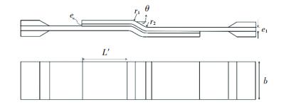 图 1 FJF胶接连接接头示意图 Fig. 1 Schematic diagram of FJF adhesively bonded joint
 1.2 BBe单元的建立 1.2.1 基本假设为简化模型,在建立BBe单元时作出如下假设.
1) 搭接区域胶层的厚度恒定,胶层应力沿厚度方向没有变化.
2) 层合板被认为是欧拉-伯努利层合梁,遵循经典层合板理论.
3) 层合板和胶层连接界面不存在缺陷[13].
1.2.2 水平段BBe单元的建立本文考虑对称铺层的复合材料层合板,从而消除了层合板的耦合效应,即耦合刚度为0.层合梁的外力和位移关系为
${{N_i} = {A_i}\frac{{{\rm{d}}{u_i}}}{{{\rm{d}}x}},}$ (1)
${{M_i} = {D_i}\frac{{{{\rm{d}}^2}{w_i}}}{{{\rm{d}}{x^2}}}.}$ (2)
式中:Ni、Mi分别表示层合板i(i=1, 2)的轴力和弯矩,ui、wi分别表示层合板i(i=1, 2)的纵向位移、挠度. Ai、Di分别表示层合板i(i=1, 2)的面内刚度和弯曲刚度.
胶层被模拟为经典双参数弹性模型[2],仅考虑其剥离应力和剪切应力,表达式为
$T = \frac{G}{e}\left( {{u_2} - {u_1} - \frac{1}{2}{e_1}{\theta _1} - \frac{1}{2}{e_2}{\theta _2}} \right),$ (3)
$S = \frac{E}{e}({w_1} - {w_2}).$ (4)
式中:E为胶层剥离方向模量,G为胶层剪切模量,e为胶层厚度,ei表示层合板i(i=1, 2)的厚度,θi表示层合板i(i=1, 2)的转角.
对层合板和胶层进行受力分析,如图 2所示.由此可以得到平衡方程:
Fig. 2
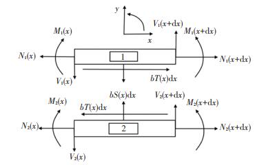 图 2 平直段段层合板与胶层受力图 Fig. 2 Free body diagram of laminated plates and the adhesive in straight section
 ${\frac{{{\rm{d}}{N_i}}}{{{\rm{d}}x}} = {{( - 1)}^i}bT,}$ (5)
${\frac{{{\rm{d}}{V_i}}}{{{\rm{d}}x}} = {{( - 1)}^{i + 1}}bS,}$ (6)
${\frac{{{\rm{d}}{M_i}}}{{{\rm{d}}x}} + {V_i} + \frac{{{e_i}}}{2}bT = 0.}$ (7)
式中:Vi为层合板i(i=1, 2)的剪力,b表示层合板i(i=1, 2)的宽度.
对式(1)~(7)进行化简可以分别得出胶层剥离应力和剪应力的通解形式:
${T = {K_1} + {K_2}{{\rm{e}}^{sx}} + {K_3}{{\rm{e}}^{ - sx}},}$ (8)
$\begin{array}{l}S = {K_4}{{\rm{e}}^{tx}}{\rm{cos}}tx + {K_5}{{\rm{e}}^{tx}}{\rm{sin}}tx + \\{\kern 1pt} {\kern 1pt} {\kern 1pt} {\kern 1pt} {\kern 1pt} {\kern 1pt} {\kern 1pt} {\kern 1pt} {\kern 1pt} {\kern 1pt} {\kern 1pt} {\kern 1pt} {\kern 1pt} {\kern 1pt} {\kern 1pt} {\kern 1pt} {\kern 1pt} {\kern 1pt} {\kern 1pt} {K_6}{{\rm{e}}^{ - tx}}{\rm{cos}}tx + {K_7}{{\rm{e}}^{ - tx}}{\rm{sin}}tx.\end{array}$ (9)
用所求的应力通解反过来可以求解层合板位移,见式(10)~(15),其中Δ表示单元长度.进而由本构关系可以求解内力.位移和内力的表达式中包含K1~K7、J1~J3、J5~J6这12个待定的系数.
${u_1} = - \frac{b}{{{k_1}{A_1}}}T - \frac{{b{K_1}}}{{2{A_1}}}{x^2} + \frac{{{J_5}}}{\Delta }x + {J_6},$ (10)
$\begin{array}{l}{u_2} = \frac{b}{{{k_1}{A_2}}}T + \frac{{b{K_1}}}{{2{A_1}}}{x^2} + \left( {\frac{{{J_5}}}{\Delta } + \frac{{2{e_1}{J_1}}}{{{\Delta ^2}}}} \right)x + {J_6} - \\{\kern 1pt} {\kern 1pt} {\kern 1pt} {\kern 1pt} {\kern 1pt} {\kern 1pt} {\kern 1pt} {\kern 1pt} {\kern 1pt} {\kern 1pt} {\kern 1pt} {\kern 1pt} {\kern 1pt} {\kern 1pt} {\kern 1pt} {\kern 1pt} {\kern 1pt} {\kern 1pt} {\kern 1pt} {\kern 1pt} {\kern 1pt} {\kern 1pt} \frac{{{e_1}{A_{10}}}}{{{k_1}}}{K_1} + \frac{{{e_1}{J_2}}}{\Delta },\end{array}$ (11)
$\begin{array}{l}{w_1} = - \frac{{{e_1}b}}{{2{D_1}k_1^2}}\frac{{{\rm{d}}T}}{{{\rm{d}}x}} + \frac{b}{{{D_1}{k_2}}}S + \frac{{b{K_1}}}{{3{e_1}{A_1}}}{x^3} + \frac{{{J_1}}}{{{\Delta ^2}}}{x^2} + \\{\kern 1pt} {\kern 1pt} {\kern 1pt} {\kern 1pt} {\kern 1pt} {\kern 1pt} {\kern 1pt} {\kern 1pt} {\kern 1pt} {\kern 1pt} {\kern 1pt} {\kern 1pt} {\kern 1pt} {\kern 1pt} {\kern 1pt} {\kern 1pt} {\kern 1pt} {\kern 1pt} {\kern 1pt} {\kern 1pt} {\kern 1pt} {\kern 1pt} {\kern 1pt} \frac{{{J_2}}}{\Delta }x + {J_3},\end{array}$ (12)
$\begin{array}{l}{w_2} = - \frac{{{e_2}b}}{{2{D_1}k_1^2}}\frac{{{\rm{d}}T}}{{{\rm{d}}x}} - \frac{b}{{{D_2}{k_2}}}S + \frac{{b{K_1}}}{{3{e_1}{A_1}}}{x^3} + \frac{{{J_1}}}{{{\Delta ^2}}}{x^2} + \\{\kern 1pt} {\kern 1pt} {\kern 1pt} {\kern 1pt} {\kern 1pt} {\kern 1pt} {\kern 1pt} {\kern 1pt} {\kern 1pt} {\kern 1pt} {\kern 1pt} {\kern 1pt} {\kern 1pt} {\kern 1pt} {\kern 1pt} {\kern 1pt} {\kern 1pt} {\kern 1pt} {\kern 1pt} {\kern 1pt} {\kern 1pt} {\kern 1pt} {\kern 1pt} \frac{{{J_2}}}{\Delta }x + {J_3},\end{array}$ (13)
$\begin{array}{l}{\theta _1} = - \frac{{{e_1}b}}{{2{D_1}{k_1}}}(T - {K_1}) + \frac{b}{{{D_1}{k_2}}}\frac{{{\rm{d}}S}}{{{\rm{d}}x}} + \frac{{b{K_1}}}{{{e_1}{A_1}}}{x^2} + \\{\kern 1pt} {\kern 1pt} {\kern 1pt} {\kern 1pt} {\kern 1pt} {\kern 1pt} {\kern 1pt} {\kern 1pt} {\kern 1pt} {\kern 1pt} {\kern 1pt} {\kern 1pt} {\kern 1pt} {\kern 1pt} {\kern 1pt} {\kern 1pt} {\kern 1pt} {\kern 1pt} {\kern 1pt} {\kern 1pt} {\kern 1pt} \frac{{2{J_1}}}{{{\Delta ^2}}}x + \frac{{{J_2}}}{\Delta },\end{array}$ (14)
$\begin{array}{l}{\theta _2} = - \frac{{{e_2}b}}{{2{D_1}{k_1}}}(T - {K_1}) - \frac{b}{{{D_2}{k_2}}}\frac{{{\rm{d}}S}}{{{\rm{d}}x}} + \frac{{b{K_1}}}{{{e_1}{A_1}}}{x^2} + \\{\kern 1pt} {\kern 1pt} {\kern 1pt} {\kern 1pt} {\kern 1pt} {\kern 1pt} {\kern 1pt} {\kern 1pt} {\kern 1pt} {\kern 1pt} {\kern 1pt} {\kern 1pt} {\kern 1pt} {\kern 1pt} {\kern 1pt} {\kern 1pt} {\kern 1pt} {\kern 1pt} {\kern 1pt} {\kern 1pt} {\kern 1pt} \frac{{2{J_1}}}{{{\Delta ^2}}}x + \frac{{{J_2}}}{\Delta }.\end{array}$ (15)
式中:
$\begin{array}{*{20}{c}}{{k_1} = \frac{b}{{{A_1}}} + \frac{b}{{{A_2}}} + \frac{{e_1^2b}}{{4{D_1}}} + \frac{{e_2^2b}}{{4{D_2}}},}\\{{k_2} = \frac{E}{e}\left( {\frac{b}{{{D_1}}} + \frac{b}{{{D_2}}}} \right),}\\{s = \sqrt {{k_1}} ,\quad t = \frac{{\sqrt 2 }}{2}{{({k_2})}^{\frac{1}{4}}}.}\end{array}$
图 3给出了BBe单元的节点位移和节点力14].分别令x=0和x=Δ,由位移和内力表达式即可求得单元节点位移和节点力关于12个待定系数的表达式:
Fig. 3
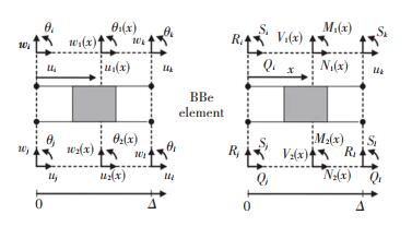 图 3 平直段BBe单元节点位移和节点力 Fig. 3 Node displacements and node forces of BBe element in straight section
 $\mathit{\boldsymbol{U}} = \left( {\begin{array}{*{20}{l}}{{u_i}}\\{{u_j}}\\{{u_k}}\\{{u_l}}\\{{w_i}}\\{{w_j}}\\{{w_k}}\\{{w_l}}\\{{\theta _i}}\\{{\theta _j}}\\{{\theta _k}}\\{{\theta _l}}\end{array}} \right) = \left[ {\begin{array}{*{20}{l}}{{u_1}(0)}\\{{u_2}(0)}\\{{u_1}(\Delta )}\\{{u_2}(\Delta )}\\{{w_1}(0)}\\{{w_2}(0)}\\{{w_1}(\Delta )}\\{{w_2}(\Delta )}\\{{\theta _1}(0)}\\{{\theta _2}(0)}\\{{\theta _1}(\Delta )}\\{{\theta _2}(\Delta )}\end{array}} \right) = \mathit{\boldsymbol{M}}\left( {\begin{array}{*{20}{l}}{{K_1}}\\{{K_2}}\\{{K_3}}\\{{K_4}}\\{{K_5}}\\{{K_6}}\\{{K_7}}\\{{J_1}}\\{{J_2}}\\{{J_3}}\\{{J_5}}\\{{J_6}}\end{array}} \right),$ (16)
$\mathit{\boldsymbol{F}} = \left( {\begin{array}{*{20}{l}}{{Q_i}}\\{{Q_j}}\\{{Q_k}}\\{{Q_l}}\\{{R_i}}\\{{R_j}}\\{{R_k}}\\{{R_l}}\\{{S_i}}\\{{S_j}}\\{{S_k}}\\{{S_l}}\end{array}} \right) = \left[ {\begin{array}{*{20}{l}}{ - {N_1}(0)}\\{ - {N_2}(0)}\\{{N_1}(\Delta )}\\{{N_2}(\Delta )}\\{ - {V_1}(0)}\\{ - {V_2}(0)}\\{{V_1}(\Delta )}\\{{V_2}(\Delta )}\\{ - {M_1}(0)}\\{ - {M_2}(0)}\\{{M_1}(\Delta )}\\{{M_2}(\Delta )}\end{array}} \right) = \mathit{\boldsymbol{N}}\left( {\begin{array}{*{20}{l}}{{K_1}}\\{{K_2}}\\{{K_3}}\\{{K_4}}\\{{K_5}}\\{{K_6}}\\{{K_7}}\\{{J_1}}\\{{J_2}}\\{{J_3}}\\{{J_5}}\\{{J_6}}\end{array}} \right).$ (17)
进而水平段BBe单元的刚度矩阵可以由式(18)求得:
${\mathit{\boldsymbol{K}}_{{\rm{BBe}}}} = \mathit{\boldsymbol{N}}{\mathit{\boldsymbol{M}}^{ - 1}}.$ (18)
1.2.3 圆弧段BBe单元的建立Mohamad[15]在研究层合壳和层合板的振动时引申了对层合曲梁的分析.层合曲梁的外力和位移关系为
${N_i} = {A_i}\left( {\frac{{{\rm{d}}{u_i}}}{{{\rm{d}}{\alpha _i}}} + \frac{{{w_i}}}{{{R_i}}}} \right),$ (19)
${M_i} = {D_i}\left( {\frac{{{{\rm{d}}^2}{w_i}}}{{{\rm{d}}\alpha _i^2}} - \frac{1}{{{R_i}}}\frac{{{\rm{d}}{u_i}}}{{{\rm{d}}{\alpha _i}}}} \right).$ (20)
对圆弧段层合板和胶层进行受力分析,如图 4所示.平衡方程为
Fig. 4
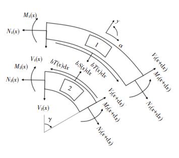 图 4 圆弧段层合板与胶层受力图 Fig. 4 Free body diagram of laminated plates and adhesive in curved section
 ${\frac{{{\rm{d}}{N_i}}}{{{\rm{d}}{\alpha _i}}} + \frac{{{V_i}}}{{{R_i}}} = {{( - 1)}^i}T,}$ (21)
${\frac{{{\rm{d}}{V_i}}}{{{\rm{d}}{\alpha _i}}} - \frac{{{N_i}}}{{{R_i}}} = {{( - 1)}^{i + 1}}S,}$ (22)
${\frac{{{\rm{d}}{M_i}}}{{{\rm{d}}{\alpha _i}}} + {V_i} + \frac{1}{2}{e_i}bT = 0.}$ (23)
用极坐标系定义,有αi=Riγ,则外力和位移关系可以转化为
${R_i^2{N_i} = {R_i}{A_i}\left( {\frac{{{\rm{d}}{u_i}}}{{{\rm{d}}\gamma }} + {w_i}} \right),}$ (24)
${R_i^2{M_i} = {D_i}\left( {\frac{{{{\rm{d}}^2}{w_i}}}{{{\rm{d}}{\gamma ^2}}} - \frac{{{\rm{d}}{u_i}}}{{{\rm{d}}\gamma }}} \right).}$ (25)
平衡方程可以转化为
${\frac{{{\rm{d}}{N_i}}}{{{\rm{d}}\gamma }} + {V_i} = {R_i}{{( - 1)}^i}T,}$ (26)
${\frac{{{\rm{d}}{V_i}}}{{{\rm{d}}\gamma }} - {N_i} = {R_i}{{( - 1)}^{i + 1}}S,}$ (27)
${\frac{{{\rm{d}}{M_i}}}{{{\rm{d}}\gamma }} + {R_i}{V_i} + \frac{1}{2}{R_i}{e_i}bT = 0.}$ (28)
由式(3)~(4)和式(24)~(28),可以得到层合板位移的耦合微分方程组,此方程组最高阶为三阶,可以令y1=u1,y2=u′1,y3=u″1,y4=w1,y5=w′1,y6=w″1,y7=u2,y8=u′2,y9=u″2,y10=w2,y11=w′2,y12=w″2,则此方程组便可转化为
$\frac{{{\rm{d}}{\mathit{\boldsymbol{Y}}^\prime }}}{{{\rm{d}}\gamma }} = \left[ \mathit{\boldsymbol{A}} \right]\mathit{\boldsymbol{Y}}.$ (29)
式中,集合Y有如下表达方式:Y={y1, y2, y3, y4, y5, y6, y7, y8, y9, y10, y11, y12}′.通过求解矩阵[A]的特征根和特征向量,即可求解出层合板位移的通解表达式,见式(30).式中nr表示特征根为实根的个数,n11=nr+1.当特征根为复数根时,将其分解为实部和虚部两部分,nim表示特征根为复数根的个数;COij(i=1, ..., nim2; j=1, 2, 3, 4)为特征根对应特征向量的元素.经化简整理得到位移通解包含C1~C12这12个待定的系数.
$\begin{array}{l}\left\{ {\begin{array}{*{20}{l}}{{u_1}}\\{{w_1}}\\{{u_2}}\\{{w_2}}\end{array}} \right\} = {C_1}\left[ {\begin{array}{*{20}{l}}{{\rm{C}}{{\rm{O}}_{11}}}\\{{\rm{C}}{{\rm{O}}_{12}}}\\{{\rm{C}}{{\rm{O}}_{13}}}\\{{\rm{C}}{{\rm{O}}_{14}}}\end{array}} \right]{e^{{\lambda _1}\theta }} + \ldots + {C_{{n_r}}}\left[ {\begin{array}{*{20}{l}}{{\rm{C}}{{\rm{O}}_{{n_r}1}}}\\{{\rm{C}}{{\rm{O}}_{{n_r}2}}}\\{{\rm{C}}{{\rm{O}}_{{n_r}3}}}\\{{\rm{C}}{{\rm{O}}_{{n_r}4}}}\end{array}} \right]{e^{{\lambda _{{n_{r}}}\theta }}} + \\{C_{{n_{11}}}}\left[ {\begin{array}{*{20}{l}}{{\rm{C}}{{\rm{O}}_{{n_{11}}1}}}\\{{\rm{C}}{{\rm{O}}_{{n_{11}}2}}}\\{{\rm{C}}{{\rm{O}}_{{n_{11}}3}}}\\{{\rm{C}}{{\rm{O}}_{{n_{11}}4}}}\end{array}} \right]{e^{{\lambda _{{n_1}}}\theta }} + {C_{{n_{12}}}}\left[ {\begin{array}{*{20}{l}}{{\rm{C}}{{\rm{O}}_{{n_{12}}1}}}\\{{\rm{C}}{{\rm{O}}_{{n_{12}}2}}}\\{{\rm{C}}{{\rm{O}}_{{n_{12}}3}}}\\{{\rm{C}}{{\rm{O}}_{{n_{12}}4}}}\end{array}} \right]{e^{{\lambda _{{n_1}}}\theta }} + \ldots \ldots + \\{C_{{n_{{n_{{\rm{im}}}}1}}}}\left[ {\begin{array}{*{20}{l}}{{\rm{C}}{{\rm{O}}_{{n_{{n_{{\rm{im}}}}1}}1}}}\\{{\rm{C}}{{\rm{O}}_{{n_{{n_{{\rm{im}}}}1}}2}}}\\{{\rm{C}}{{\rm{O}}_{{n_{{n_{{\rm{im}}}}1}}3}}}\\{{\rm{C}}{{\rm{O}}_{{n_{{n_{{\rm{im}}}}1}}4}}}\end{array}} \right]{e^{{\lambda _{{n_{{n_{{\rm{im}}}}}}}}\theta }} + {C_{{n_{{n_{{\rm{im}}}}2}}}}\left[ {\begin{array}{*{20}{l}}{{\rm{C}}{{\rm{O}}_{{n_{{n_{{\rm{im}}}}2}}1}}}\\{{\rm{C}}{{\rm{O}}_{{n_{{n_{{\rm{im}}}}2}}2}}}\\{{\rm{C}}{{\rm{O}}_{{n_{{n_{{\rm{im}}}}2}}3}}}\\{{\rm{C}}{{\rm{O}}_{{n_{{n_{{\rm{im}}}}2}}4}}}\end{array}} \right]{e^{{\lambda _{{n_{{n_{{\rm{im}}}}}}}}\theta }}.\end{array}$ (30)
用位移通解求解层合板内力,分别令γ=0和γ=γ0,即可求得单元节点位移和节点力关于12个待定系数的表达式,进而由式(18)求得圆弧段BBe单元的刚度矩阵.
1.3 非搭接区梁单元和总体刚度矩阵非搭接区的平衡方程为
${\frac{{{\rm{d}}{N_i}}}{{{\rm{d}}x}} = 0,}$ (31)
${\frac{{{\rm{d}}{V_i}}}{{{\rm{d}}x}} = 0,}$ (32)
$\frac{{{\rm{d}}{M_i}}}{{{\rm{d}}x}} + {V_i} = 0.$ (33)
求解非搭接区梁单元刚度矩阵参照求解BBe单元刚度矩阵的思路,求得的刚度矩阵为
${\mathit{\boldsymbol{K}}_{{\rm{beam}}}} = \left[ {\begin{array}{*{20}{c}}{\frac{{{A_i}}}{{{l_i}}}}&{ - \frac{{{A_i}}}{{{l_i}}}}&0&0&0&0\\{\frac{{{A_i}}}{{{l_i}}}}&{\frac{{{A_i}}}{{{l_i}}}}&0&0&0&0\\0&0&{\frac{{12{\Delta _i}}}{{l_i^3{A_i}}}}&{ - \frac{{12{\Delta _i}}}{{l_i^3{A_i}}}}&{\frac{{6{\Delta _i}}}{{l_i^2{A_i}}}}&{\frac{{6{\Delta _i}}}{{l_i^2{A_i}}}}\\0&0&{ - \frac{{12{\Delta _i}}}{{l_i^3{A_i}}}}&{\frac{{12{\Delta _i}}}{{l_i^3{A_i}}}}&{ - \frac{{6{\Delta _i}}}{{l_i^2{A_i}}}}&{ - \frac{{6{\Delta _i}}}{{l_i^2{A_i}}}}\\0&0&{\frac{{6{\Delta _i}}}{{l_i^2{A_i}}}}&{ - \frac{{6{\Delta _i}}}{{l_i^2{A_i}}}}&{\frac{1}{{{l_i}}}\left( {\frac{{3{\Delta _i}}}{{{A_i}}} + {D_i}} \right)}&{\frac{1}{{{l_i}}}\left( {\frac{{3{\Delta _i}}}{{{A_i}}} + {D_i}} \right)}\\0&0&{\frac{{6{\Delta _i}}}{{l_i^2{A_i}}}}&{ - \frac{{6{\Delta _i}}}{{l_i^2{A_i}}}}&{\frac{1}{{{l_i}}}\left( {\frac{{3{\Delta _i}}}{{{A_i}}} + {D_i}} \right)}&{\frac{1}{{{l_i}}}\left( {\frac{{3{\Delta _i}}}{{{A_i}}} + {D_i}} \right)}\end{array}} \right].$ (34)
式中li为非搭接区梁i的长度,Δi=AiDi.
对整体胶接接头进行网格离散,如图 5所示(此处每段仅划分1个单元用于示意).总体刚度矩阵基于经典有限元方法,由各个单元的刚度矩阵求得.
Fig. 5
 图 5 FJF胶接接头网格离散 Fig. 5 Mesh discretization of FJF adhesively bonded joint
 2 FJF胶接连接接头有限元模型胶接接头胶层应力分析采用三维有限元模型,如图 6所示.接头基本几何参数如表 1所示.
Fig. 6
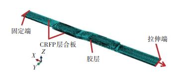 图 6 CFRP FJF胶接连接接头三维有限元模型 Fig. 6 3D Finite Element Model of CFRP FJF adhesively bonded joint
 表 1
L′/mm 42.95
e1/mm 2
b/mm 16
r1/mm 30
e/mm 0.2
θ/mm 7.83
表 1 FJF胶接接头基本几何参数 Tab. 1 Basic geometric parameters of FJF adhesively bonded joint
层合板选用T700/5429碳纤维增强双马来酰亚胺树脂基复合材料,单向板的基本材料属性如下[16]:E1=133 GPa,E2=9.1 GPa,ν12=0.31,G12=5.67 GPa,G13=5.67 GPa,G23=3.5 GPa,XT=2 507 MPa,XC=1201 MPa,YT=61.8 MPa,YC=186 MPa,S12=84.8 MPa,S13=84.8 MPa,S23=41.6 MPa.其中,E1、E2分别为单向板纵、横向的弹性模量;G12、G13、G23为单向板剪切模量;ν12为单向板纵向的泊松比;XT、XC分别为单向板纵向拉伸、压缩强度;YT,YC分别为单向板横向拉伸、压缩强度;S12、S13、S23为单向板剪切强度.胶层材料采用J299高韧性双马结构胶膜,弹性模量为2.92 GPa,泊松比为0.47.
模型中碳纤维层合板属性采用等效工程常数,由单层板的面内材料属性和铺层信息计算得出,单元类型为三维实体单元C3D8R.胶层同样采用三维实体单元C3D8R,胶层单元与层合板单元通过共节点连接.在接头搭接区两侧端部和圆角过渡区通过加密网格的方式以便更好地捕捉应力信息,考虑到胶层的厚度尺寸,搭接区两侧端部的网格大小设置为0.2 mm,且向远离端部长度和厚度方向采用渐变种子布局,搭接区端部局部网格加密如图 7所示.
Fig. 7
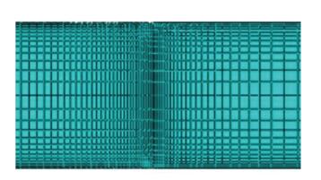 图 7 局部网格加密图 Fig. 7 Local mesh refinement
 3 结果与分析 3.1 网格收敛性分析对在胶层厚度上划分网格数na取值2、4、8、16、32和64,在外载为1 kN的条件下获取胶层端部最大剥离应力和最大剪切应力值,结果如图 8和图 9所示.
Fig. 8
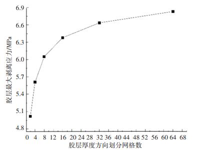 图 8 胶层厚度方向不同网格数量下接头端部最大剥离应力 Fig. 8 Maximal peel stresses at the joint end with different mesh numbers along the adhesive thickness
 Fig. 9
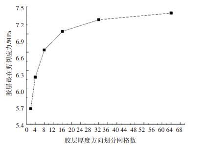 图 9 胶层厚度方向不同网格数量下接头端部最大剪切应力 Fig. 9 Maximal shear stresses at the joint end with different mesh numbers along the adhesive thickness
 由图 8和图 9可知,随着胶层厚度方向网格数量的不断增大,胶层端部最大剥离应力和最大剪切应力值趋于稳定,表明网格逐渐收敛.
3.2 不同模型胶层应力对比分析采用收敛的网格划分胶层厚度,在后处理中获得胶层剥离应力和剪切应力沿搭接区长度方向的应力分布,并与半解析模型计算得到的胶层应力分布进行对比,如图 10和图 11所示.由图 10和图 11可知,由半解析模型计算得到的胶层剥离应力和剪切应力分布与三维有限元模型得到的对应应力分布基本一致.胶层最大剥离应力和剪切应力均在搭接区端部,且两端基本对称.半解析模型胶层端部剥离应力值为6.46 MPa,相较于三维有限元模型胶层端部剥离应力值(6.83 MPa)误差绝对值为5.4%;半解析模型胶层端部剪切应力值为6.98 MPa,相较于三维有限元模型胶层端部剪切应力值(7.25 MPa)误差绝对值为3.7%.
Fig. 10
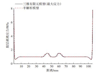 图 10 三维有限元模型与半解析模型胶层剥离应力分布对比 Fig. 10 Comparison of adhesive peel stress distributions between 3D Finite Element Model and semi-analytical model
 Fig. 11
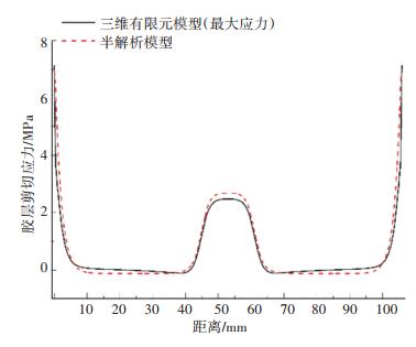 图 11 三维有限元模型与半解析模型胶层剪切应力分布对比 Fig. 11 Comparison of adhesive shear stress distributions between 3D Finite Element Model and semi-analytical model
 4 胶层宽度和厚度的影响研究表明,胶层厚度[17]和胶层宽度[18]对复合材料胶接接头搭接区胶层应力均有影响.由此,基于半解析模型对不同胶层宽度和厚度组合条件下胶层应力分布进行对比分析,组合如表 2所示.对比第1、2和3组可以得出在胶层厚度一定的情况下,胶层宽度对搭接区胶层应力的影响;对比第3、4和5组可以得出在胶层宽度一定的情况下,胶层厚度对搭接区胶层应力的影响.
表 2
1 20 0.1
2 16 0.1
3 12 0.1
4 12 0.2
5 12 0.3
表 2 不同胶层宽度和厚度组合 Tab. 2 Different width and thickness combinations of the adhesive
5组宽度和厚度组合条件下胶层剥离应力分布和剪切应力分布对比如图 12和图 13所示.将端部和圆弧处剥离应力与剪切应力峰值统计于表 3.
Fig. 12
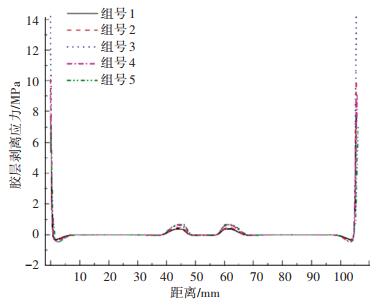 图 12 不同宽度和厚度组合下胶层剥离应力分布对比 Fig. 12 Comparison of adhesive peel stress distributions under different width and thickness combinations
 Fig. 13
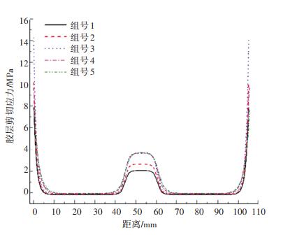 图 13 不同宽度和厚度组合下胶层剪切应力分布对比 Fig. 13 Comparison of adhesive shear stress distributions under different width and thickness combinations
 表 3
1 2 3 4 5
剥离应力/ 端部 7.73 10.11 14.20 9.12 7.06
MPa 圆角 0.39 0.48 0.63 0.66 0.69
剪切应力/ 端部 7.82 10.17 14.25 9.64 7.75
MPa 圆角 2.05 2.64 3.62 3.67 3.69X
表 3 不同宽度和厚度组合下胶层搭接区端部和圆角处应力峰值 Tab. 3 Stress peak values of the adhesive at the end and the fillet of the overlap zone under different width and thickness combinations
根据表 3的统计结果可以得出,搭接区端部胶层剥离应力和剪切应力值在胶层宽度一定时随胶层厚度的增加而降低,在胶层厚度一定时随胶层宽度的增加而降低.搭接区圆角胶层剥离应力和剪切应力值在胶层厚度一定时随胶层宽度的增加而降低,在胶层宽度一定时随胶层厚度的增加而增加.
5 结论为了快速、准确地计算CFRP平-折-平胶接连接接头应力,本文建立了接头半解析模型,并与三维有限元模型结果进行对比,同时对不同胶层宽度和厚度下搭接区胶层应力进行对比分析,得出以下结论:
1) 该模型基于线弹性一维梁模型构造了圆弧段BBe单元,基于有限元方法,求得搭接区胶层剥离应力和剪切应力的分布,为碳纤维复合材料FJF胶接连接接头应力分析提供了一定的借鉴作用.
2) 所建立的CFRP平-折-平胶接连接接头半解析模型计算得出的胶层剥离应力和剪切应力分布与三维有限元模型得到的对应应力分布基本一致.搭接区端部胶层剥离应力和剪切应力相较于三维有限元模型计算结果的误差绝对值分别为5.4%和3.7%,具有比较好的计算精度.
3) 搭接区端部胶层剥离应力和剪切应力值在胶层宽度一定时随胶层厚度的增加而降低,在胶层厚度一定时随胶层宽度的增加而降低.
4) 搭接区圆角胶层剥离应力和剪切应力值在胶层厚度一定时随胶层宽度的增加而降低,在胶层宽度一定时随胶层厚度的增加而增加.
参考文献
[1] VOLKERSEN O. Die Nietkraftverteilung in zugbeanspruchten nietverbindungen mit konstanten laschenquerschnitten[J]. Luftfahrtforschung, 1938, 15: 41.
[2] GOLAND M, REISSNER E. The stresses in cemented joints[J]. Journal of Applied Mechanics of ASME, 1944, 11: A17.
[3] SILVA L F M D, NEVES P J C D, ADAMS R D, et al. Analytical models of adhesively bonded joints-part I: literature survey[J]. International Journal of Adhesion and Adhesives, 2009, 29(3): 319. DOI:10.1016/j.ijadhadh.2008.06.005
[4] SILVA L F M D, NEVES P J C D, ADAMS R D, et al. Analytical models of adhesively bonded joints-part Ⅱ: comparative study[J]. International Journal of Adhesion and Adhesives, 2009, 29(3): 331. DOI:10.1016/j.ijadhadh.2008.06.007
[5] 赵波, 吕振华. 单搭接胶接接头弹性应力的二维分析方法[J]. 应用力学学报, 2009, 26(3): 608.
ZHAO Bo, LV Zhenhua. Elastic stress analysis of single-lap adhesive-bonded joints[J]. Chinese Journal of Applied Mechanics, 2009, 26(3): 608.
[6] ZHAO B, LV Z H, LV Y N. Closed-form solutions for elastic stress-strain analysis in unbalanced adhesive single-lap joints considering adherend deformations and bond thickness[J]. International Journal of Adhesion and Adhesives, 2011, 31: 434. DOI:10.1016/j.ijadhadh.2011.03.002
[7] YOUSEFSANI S A, TAHANI M. Analytical solutions for adhesively bonded composite single-lap joints under mechanical loadings using full layerwise theory[J]. International Journal of Adhesion and Adhesives, 2013, 43: 32. DOI:10.1016/j.ijadhadh.2013.01.012
[8] YOUSEFSANI S A, TAHANI M. Accurate determination of stress distributions in adhesively bonded homogeneous and heterogeneous double-lap joints[J]. European Journal of Mechanics/A Solids, 2013, 39: 197. DOI:10.1016/j.euromechsol.2012.12.001
[9] SELAHI M T E, YOUSEFSANI S A. Analytical solution of stress field in adhesively bonded composite single-lap joints under mechanical loadings[J]. International Journal of Engineering, 2014, 27: 475. DOI:10.5829/idosi.ije.2014.27.03c.16
[10] PAROISSIEN E, GAUBERT F, DA VEIGA A, et al. Elasto-plastic analysis of bonded joints with macro-elements[J]. Journal of Adhesion Science and Technology, 2013, 27: 1464. DOI:10.1080/01694243.2012.745053
[11] PAROISSIEN E, LACHAUD F, SILVA L F M D, et al. A comparison between macro-element and finite element solutions for the stress analysis of functionally graded single-lap joints[J]. Composite Structures, 2019, 215: 331. DOI:10.1016/j.compstruct.2019.02.070
[12] KISHORE A N, PRASAD N S. An experimental study of Flat-Joggle-Flat bonded joints in composite laminates[J]. International Journal of Adhesion and Adhesives, 2012, 35: 55. DOI:10.1016/j.ijadhadh.2012.02.003
[13] 赵波. 考虑弯曲效应的混元胶接单搭接头应力模型[J]. 机械工程学报, 2008, 44(10): 129.
ZHAO Bo. Theoretical stress model of mixed-modulus single-ap adhesive bonded joints considering the bending effect[J]. Chinese Journal of Mechanical Engineering, 2008, 44(10): 129. DOI:10.3321/j.issn:0577-6686.2008.10.021
[14] LELIAS G, PAROISSIEN E, LACHAUD F, et al. An extended semi-analytical formulation for fast and reliable mode I/Ⅱ stress analysis of adhesively bonded joints[J]. International Journal of Solids and Structures, 2015, 62: 18. DOI:10.1016/j.ijsolstr.2014.12.027
[15] MOHAMAD S Q. Vibration of laminated shells and plates[M]. Pittsburgh: Academic Press, 2004: 76.
[16] 王毅, 冯宪章, 李磊, 等. 复合材料层合板二次共固化补强胶层失效分析研究[J]. 机械强度, 2012, 34(6): 862.
WANG Yi, FENG Xianzhang, LI Lei, et al. Bonding adhesive damage study of the secondary co-cure reinforcement tensile experiment[J]. Journal of Mechanical Strength, 2012, 34(6): 862. DOI:10.16579/j.issn.1001.9669.2012.06.011
[17] 张银银, 杨银环, 刘思远. 层合板单搭胶接接头应力的三维有限元分析[J]. 哈尔滨商业大学学报(自然科学版), 2018, 34(6): 727.
ZHANG Yinyin, YANG Yinhuan, LIU Siyuan. Three-dimensional finite element stress analysis of single-lap laminates adhesively joints[J]. Journal of Harbin University of Commerce (Natural Sciences Edition), 2018, 34(6): 727. DOI:10.19492/j.cnki.1672-0946.2018.06.020
[18] 彭海俊.几何参数对复合材料厚胶层胶接的影响研究[D].武汉: 武汉理工大学, 2017: 21
PENG Haijun. Effects of geometrical dimensions on composite bonded Joints featured with thick adhesive layer[D]. Wuhan: Wuhan University of Technology, 2017: 21 https://www.ixueshu.com/document/994906362d7885de7da3ab7707926d29318947a18e7f9386.html
