Min Wang1,2, Qiang Li2,Xin gang Liang2
(1.School of Astronautics, Beihang University, Beijing 100191, China;2. China Academy of Space Technology, Beijing 100094, China)
Abstract:
Electric propulsion is used for all electric propulsion satellites to perform the orbit transfer, attitude control and station-keeping tasks. Generally electric propulsion subsystem contains 4 thrusters. But if one thruster fails in the beginning of satellite lifetime, other thrusters will undertake all the firing tasks. The firing time will be 2 to 3 times of thrusters without failure. Thus it may go beyond the allowed lifetime of thruster. This paper puts forward two thruster redundancy configuration solutions with 6 thrusters to solve this problem. Two layout configurations and their corresponding station-keeping strategies are simulated and compared. The results show that the maximum firing time of both layout configurations can meet the lifetime limitation. This solution is a good reference for all electric propulsion satellites design.
Key words: all electric propulsion satellite station-keeping electric thrusters configuration electric thruster layout failure redundancy
DOI:10.11916/j.issn.1005-9113.17033
Clc Number:V423.4
Fund:
Min Wang, Qiang Li, Xin' gang Liang. Electric Thrusters Redundancy Configuration Strategy Study for All Electric Propulsion Platform Station-Keeping[J]. Journal of Harbin Institute of Technology (New Series), 2018, 25(3): 55-61. DOI: 10.11916/j.issn.1005-9113.17033.

Corresponding author Min Wang, E-mail:642491517@qq.com Article history Received: 2017-02-25
Contents Abstract Full text Figures/Tables PDF
Electric Thrusters Redundancy Configuration Strategy Study for All Electric Propulsion Platform Station-Keeping
Min Wang1,2

 , Qiang Li2, Xin' gang Liang2
 1. School of Astronautics, Beihang University, Beijing 100191, China;
2. China Academy of Space Technology, Beijing 100094, China
Received: 2017-02-25
Corresponding author: Min Wang, E-mail:642491517@qq.com
Abstract: Electric propulsion is used for all electric propulsion satellites to perform the orbit transfer, attitude control and station-keeping tasks.Generally electric propulsion subsystem contains 4 thrusters.But if one thruster fails in the beginning of satellite lifetime, other thrusters will undertake all the firing tasks.The firing time will be 2 to 3 times of thrusters without failure.Thus it may go beyond the allowed lifetime of thruster.This paper puts forward two thruster redundancy configuration solutions with 6 thrusters to solve this problem.Two layout configurations and their corresponding station-keeping strategies are simulated and compared.The results show that the maximum firing time of both layout configurations can meet the lifetime limitation.This solution is a good reference for all electric propulsion satellites design.
Key words: all electric propulsion satellite station-keeping electric thrusters configuration electric thruster layout failure redundancy
1 Introduction Electric thrusters become the standard configuration of geostationary earth orbit satellite with high specific impulse, which can save fuel.Nowadays, electric thruster can meet the requirements of orbit transfer, station-keeping and moment dumpling, more than just station-keeping[1-2].
On Boeing 702SP all-electric-thruster satellite platform, four electric thrusters are configured as square between the back floor and the south and north floor, the pointing direction can be regulated accurately with thruster pointing assembly mechanism.The configuration can meet the requirements of orbit transfer, station-keeping and moment dumpling, which is the most common configuration on geostationary earth orbit.Similarly, the "V" configuration is only for the use of station-keeping on HS-601 satellite platform[3], as well as the movable square configuration on Electra satellite platform[4], which expands the two axes thruster pointing assembly mechanism to multiple degrees of freedom mechanical arm.Besides square configuration, the "X" configuration is used on SGEO satellite platform with 8 thrusters in separate path to backup each other mounted between the east and west floor and the south and north floor, which meets the requirements of station-keeping and moment dumpling by combining different thrusters, so thruster pointing assembly mechanism is not necessary[5-7].In these configurations, the Boeing 702SP satellite platform is more powerful and more widely used.
Four electric thrusters are mounted on the Boeing 702SP all-electric-thruster satellite platform.The four thrusters can work at the same time while every two thrusters can be the backup of the other two.But if a thruster encounters failure on early stage of lifetime, the firing time will be 2 to 3 times of thrusters without failure, which may exceed the designed work time.In this article, a redundancy configuration scheme with 6 thrusters is designed to solve the problem.
2 Electric Thruster Redundancy Configuration Schemes 4 thrusters are mounted on the back floor, near to the edges of the south and north floor.The thrust direction points to satellite centroiding location.In this article, the initial mass of the satellite on orbit is 3 200 kg, station-keeping velocity increment in 15 years is about 700 m/s, the thrust of a electric thruster is 40 mN, and the specific impulse of is 40 mN, the allowed maximum work time of a thruster is 15 000 h.Then in normal case every thruster's work time is 8 000 h in the configuration of four thrusters.If a thruster encounters failure on early stage of lifetime, the maximum work time of the backup thruster is 18 000 h, which exceeds the designed work time.
So, new configuration scheme of the thrusters should be made by means of adding thrusters as little as possible, designing new configuration and reducing the maximum work time of a thruster.
If one thruster is added (south side for instance), the work time of the remain one thruster in north side will not be changed, which cannot meet the lifetime requirement.So two thrusters are necessary.The schemes of the configuration of two thrusters are as belows.
(1) Two electric thruster are mounted in symmetry method between the existing four thrusters, as shown in Fig. 1 and Fig. 2 (the existing four thruster is numbered 1, 2, 3, 4, the new two thrusters are numbered 7 and 8.The x and y coordinate axes point to eigenaxis.The x axis points to the east and the y axis points to the north on orbit).
Figure 1
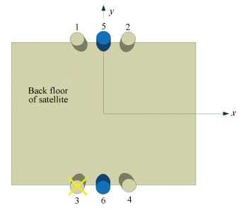 Figure 1 Six electric thrusters configuration in scheme 1
 Figure 2
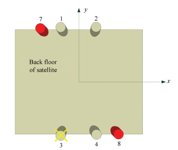 Figure 2 Six electric thrusters configuration in scheme 2
 (2) Two electric thrusters are mounted in skewed symmetry method in east and west side of the existing thrusters, as shown in Fig. 2 (the new two thrusters are numbered 7 and 8):
When a electric thruster encounters failure (for example, the third thruster is with failure in this article), according to basic principle of station-keeping[8-12], the firing time must meet the constraints below:
$\left\{ \begin{array}{l}\frac{F}{m}{K_{\rm{N}}}\left( {{T_{{\rm{north}}}} + {T_{{\rm{south}}}}} \right) = {V_s}\Delta i\\\frac{F}{m}{K_{\rm{T}}}\left( {{T_{{\rm{east}}}} + {T_{{\rm{west}}}}} \right) = - \frac{{{R_s}}}{3}\Delta D\end{array} \right.$ (1)
In Eq.(1), (F/m) is the ratio between thrust and mass, KN is normal projection coefficient, KT is tangential projection coefficient, Tnorth is the sum of all thrusters in north side firing time, Tsouth is the sum of all thrusters in south side firing time, Teast is the sum of all thrusters in east side firing time, Twest is the sum of all thrusters in west side firing time, Vs and Rs are geostationary Earth orbit nominal velocity and radius of the orbit, Δi and ΔD are inclination and eccentricity control quantity (if the station-keeping strategy is fixed period, the two quantity is almost fixed as well).
From formula (1) we know that scheme 1 is a feasible plan.Because the remained thruster (1, 4, 5, 6) has four direction components in east, west, south and north, thruster 5 and 6 can be the backup of thruster 1 and 4, which can share the working time.Thruster 7 and 8 can be the backup of thruster 1 and 4, which can share the working time.The increased thrusters' mass is only 5% of the satellite dry weight, so its influence to the thruster working time is negligible in this article.The following is the analysis of the thruster's performance in both schemes.
3 Electric Thruster Configuration Redundancy Analysis Redundancy means that the system still complete the task of station-keeping and permits the maximum arbitrary failed thrusters.Station-keeping needs the control of inclination vector Δi, eccentricity vector Δe and mean longitude λ[13-15].Before analyzing the redundancy of electric propulsion system, the first is to analyze the minimum thruster configuration.Here shows the station-keeping control degrees of freedom.
The relative relation of the eccentricity vector change and inclination vector change caused by one electric thruster ignition is fixed (as shown in Fig. 3, in which δe=arctan(KR/2KT) is the coupling angle of the inclination-eccentricity, which is related to the thrusters layout position.KR is the shadow coefficient at radial direction as well as KT is at the tangential direction), however, the mean longitude control and the inclination-eccentricity control do not affect each other.
Figure 3
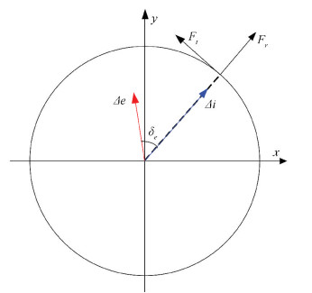 Figure 3 The coupling relation of the inclination-eccentricity
 The number of the minimum independent control variables that thrusters igniting in any way to achieve complete control of the inclination and eccentricity are named as control degrees of freedom.
The eccentricity vector change and inclination vector change caused by one electric thruster N times ignition are:
$\left\{ \begin{array}{l}\Delta i = \left[ {\begin{array}{*{20}{c}}{\Delta {i_x}}\\{\Delta {i_y}}\end{array}} \right] = \frac{1}{{{V_s}}}\sum\limits_{k = 1}^N {{K_N}\Delta {V_k}\left[ {\begin{array}{*{20}{c}}{\cos \left( {{l_k}} \right)}\\{\sin \left( {{l_k}} \right)}\end{array}} \right]} = \\\;\;\;\;\;\;\;\frac{{{K_{\rm{N}}}}}{{{V_{\rm{s}}}}}\sum\limits_{k = 1}^N {\Delta {V_k}{{\mathit{\boldsymbol{\bar i}}}_k}} \\\Delta e = \left[ {\begin{array}{*{20}{c}}{\Delta {e_x}}\\{\Delta {e_y}}\end{array}} \right] = \frac{1}{{{V_s}}}\sum\limits_{k = 1}^N {\Delta {V_k}\left( {2{K_{\rm{T}}}\left[ {\begin{array}{*{20}{c}}{\cos \left( {{l_k}} \right)}\\{\sin \left( {{l_k}} \right)}\end{array}} \right] + } \right.} \\\;\;\;\;\;\;\;\left. {{K_{\rm{R}}}\left[ {\begin{array}{*{20}{c}}{\sin \left( {{l_k}} \right)}\\{ - \cos \left( {{l_k}} \right)}\end{array}} \right]} \right) = \frac{{\sqrt {4K_{\rm{T}}^2 + K_{\rm{R}}^2} }}{{{V_s}}}\sum\limits_{k = 1}^N {\Delta {V_k}{{\mathit{\boldsymbol{\bar e}}}_k}} \end{array} \right.$ (2)
Where ΔVk is velocity increment, lk is the satellite longitude at the middle time of ignition, ik and ek are unit vectors.
$\begin{array}{*{20}{c}}{{{\mathit{\boldsymbol{\bar i}}}_k} = \left[ {\begin{array}{*{20}{c}}{\cos \left( {{l_k}} \right)}\\{\sin \left( {{l_k}} \right)}\end{array}} \right]}\\{{{\mathit{\boldsymbol{\bar e}}}_k} = \frac{1}{{\sqrt {4K_{\rm{T}}^2 + K_{\rm{R}}^2} }}\left( {2{K_{\rm{T}}}\left[ {\begin{array}{*{20}{c}}{\cos \left( {{l_k}} \right)}\\{\sin \left( {{l_k}} \right)}\end{array}} \right] + {K_{\rm{R}}}\left[ {\begin{array}{*{20}{c}}{\sin \left( {{l_k}} \right)}\\{ - \cos \left( {{l_k}} \right)}\end{array}} \right]} \right)}\end{array}$ (3)
where ik and ek are only related to the thrusters layout position and the satellite longitude at the intermediate instant of ignition.The phase angle of ik and ek is fixed.It can be known that the eccentricity vector change and inclination vector change caused by one electric thruster N times ignition still keep fixed-phase.So it can be taken as one ignition.And in this ignition, the velocity increment ΔVk′ and the satellite longitude at the intermediate instant lk′ are:
$\left\{ \begin{array}{l}{l_{k'}} = \arg \left( {\sum\limits_{k = 1}^N {\Delta {V_k}{{\mathit{\boldsymbol{\bar i}}}_k}} } \right)\\\Delta {V_{k'}} = \left| {\sum\limits_{k = 1}^N {\Delta {V_k}{{\mathit{\boldsymbol{\bar i}}}_k}} } \right|\end{array} \right.$ (4)
So, a thruster only has two degrees of freedom to eccentricity and inclination, not related to ignition times.Because the velocity increment and the satellite longitude are functions of inclination vector change, we can use inclination vector change as control variable.Considering two thrusters ignite separately, the change of eccentricity vector and inclination vector is:
$\begin{array}{l}\left[ {\begin{array}{*{20}{c}}{\Delta \mathit{\boldsymbol{i}}}\\{\Delta \mathit{\boldsymbol{e}}}\end{array}} \right] = \left[ {\begin{array}{*{20}{c}}{\Delta {i_{1x}} + \Delta {i_{2x}}}\\{\Delta {i_{1y}} + \Delta {i_{2y}}}\\{\Delta {e_{1x}} + \Delta {e_{2x}}}\\{\Delta {e_{1y}} + \Delta {e_{2y}}}\end{array}} \right] = \\\;\;\;\;\;\;\left[ {\begin{array}{*{20}{c}}1&0&1&0\\0&1&0&1\\{\cos {\delta _{1e}}}&{\sin {\delta _{1e}}}&{\cos {\delta _{2e}}}&{\sin {\delta _{2e}}}\\{ - \sin {\delta _{1e}}}&{\cos {\delta _{1e}}}&{ - \sin {\delta _{2e}}}&{\cos {\delta _{2e}}}\end{array}} \right]\left[ {\begin{array}{*{20}{c}}{{{\bar i}_{1x}}}\\{{{\bar i}_{1y}}}\\{{{\bar i}_{2x}}}\\{{{\bar i}_{2y}}}\end{array}} \right] = \\\;\;\;\;\;\;\mathit{\boldsymbol{A}}\left[ {\begin{array}{*{20}{c}}{{{\bar i}_{1x}}}\\{{{\bar i}_{1y}}}\\{{{\bar i}_{2x}}}\\{{{\bar i}_{2y}}}\end{array}} \right]\end{array}$ (5)
where Δi1x, Δi1y, Δi2x, Δi2y are four independent control variables that the two thrusters can provide.If the matrix A is full rank, the two thrusters have 4 control degrees of freedom to the eccentricity and inclination vectors.It can achieve the complete control to the eccentricity and inclination vectors.The condition that the matrix A is full rank is:
$\begin{array}{l}\det \left( \mathit{\boldsymbol{A}} \right) \ne 0 \Leftrightarrow \\\;\;\;\;\;{\left( {\cos {\delta _{1e}} - \cos {\delta _{2e}}} \right)^2} + {\left( {\sin {\delta _{1e}} - \sin {\delta _{2e}}} \right)^2} \ne \\\;\;\;\;\;0 \Leftrightarrow {\delta _{1e}} \ne {\delta _{2e}}\end{array}$ (6)
The above formula demonstrates that the matrix A is full rank when δ1e≠δ2e.Because coupling angle δe is only a function of the thruster layout position, the conclusion can be drawn that the combination of 2 arbitrary thrusters has 4 control degrees of freedom to the eccentricity and inclination.While the coupling angle of 2 thrusters is close, according to the vector synthesis, the efficiency of maintaining the position is very low.When the coupling angle of two thrusters is 180° from each other, the efficiency of station keeping efficiency is the best.
The control of mean longitude only needs tangential thrust and one thruster can only provide the tangential thrust to the east or the west with the zero control freedom degree of mean longitude.The control freedom degree of mean longitude is 1 in the condition that there is a combination of two thrusters which can provide the tangential thrust to the east or the west at the same time.
Assume the horizontal distance between thrusters is 600 mm, the longitudinal distance is 2 600 mm, the centroid height is 1 600 mm (the direction of thrusters is pointed to centriod).The coupling angle and tangential thrust of the 8 thrusters involved in the scheme 1 and the scheme 2 are shown in Table 1.
表 1
1 69.444 0 East
2 110.556 0 West
3 249.444 0 East
4 290.556 0 West
5 90.000 0 No tangential component
6 270.000 0 No tangential component
7 53.130 1 East
8 306.869 9 West
Table 1 The coupling angle and the tangential thrust direction of the thruster
Based on the above analysis, it can be known that among 4 rectangular configuration thrusters 1, 2, 3 and 4, the combination that can achieve completely maintaining position included:1-2, 1-4, 3-2, 3-4, and the permitted maximum number of arbitrary broken thrusters is 1.The added 5 and 6 thrusters in scheme 1 are not able to provide the tangential component, so it cannot increase the system redundancy.The added 7 and 8 thrusters in scheme 2 are able to provide the combination of the complete maintaining the position:7-2, 7-4, 8-1, 8-3, and the permitted maximum number of arbitrary broken thrusters is 2.The system redundancy increases from 1 to 2.
4 Design and Simulation of Position-keeping Strategy In the limiting working condition, if there is one thruster broken at the beginning of lifetime, the strategy of station-keeping needs to be designed properably, so that the left working time of the thruster is balanced as far as possible and the longest working time of one thruster can satisfy the limitation of the working lifetime.
The station-keeping strategy of scheme 1 shows below:
1) Using the thruster 1, 4, 5 and 6 to maintain the position.These four thrusters ignite each one time uas one control cycle.Usually it is two-day period for one control cycle.After a certain amount of control cycles, the free two days left are specially used for orbit-confirming rather than station-keeping[16-20].
2) The thruster 1 and the thruster 4 make the mean longitude control and part of inclination control.And the thruster 5 and the thruster 6 make part of inclination control and the whole eccentricity control.The inclination proportion that the combination 1-4 and combination 5-6 afford can be adjusted in order to make the longest working time of one thrust lowest.
According to the above strategy of station-keeping, and after the simulation, the conclusion that the time of thrusters ignition with station-keeping per year as shown in Table 2 and Figs. 4-5.The proportion of the combination 1-4 and combination 7-8 in 15 years life is 1:1.
表 2
1 1.868 292.406 6.753 9 267.361
4 3.822 598.273
5 3.947 617.824
9 2.155 337.362
Table 2 Statistics of thrusters igniting time in Scheme-two
Figure 4
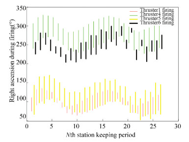 Figure 4 The thruster ignition arc in scheme 1
 Figure 5
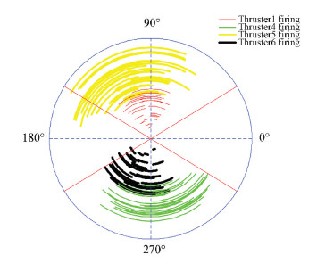 Figure 5 Distribution of the thruster ignition arc in scheme 1
 The station-keeping strategy of scheme 2 shows below:
1) Using two thrusters when maintaining the position (such as 1-4 combination or 7-8 combination), and two thrusters ignite each one time as a control cycle.Usually it is two-day period for a control cycle.After a certain amount of control cycles, the free two days left are specially used for orbit-confirming rather than station-keeping.
2) The proportion that the combination 1-4 and combination 7-8 afford in 15 years life can be adjusted in order to make the longest working time of one thrust lowest.
According to the above strategy of the station-keeping, and after the simulation, the conclusion that the time of thrusters ignition with station-keeping in one year as shown in Table 3 and Figs. 6-9.The proportion of the combination 1-4 and combination 7-8 in 15 years life is 1.05:1.
表 3
NW(1) 6.020 942.3038.0157.691 9 602.476
SE(4) 7.976 1 248.546
NW(7) 7.323 1 146.3149.000 7.309 9 602.476
SE(8) 8.393 1 313.774
Table 3 Statistics of thrusters igniting time in scheme 2
Figure 6
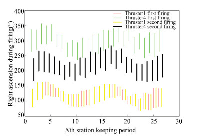 Figure 6 The ignition arc with the thruster 1-4 working in scheme 2
 Figure 7
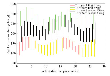 Figure 7 The ignition arc with the thruster 7-8 working in scheme 2
 Figure 8
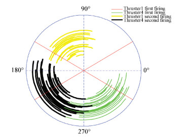 Figure 8 Distribution of the ignition arc with the thruster 1-4 working in scheme 2
 Figure 9
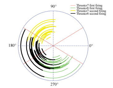 Figure 9 Distribution of the ignition arc with the thruster 7-8 working in scheme 2
 Table 4 shows comparison between the two schemes.
表 4
Scheme 1 1 9 267 6.753 If one thruster fails, the thrusters in other pairs can afford all the firing tasks of 15 years.If two thrusters in east pair or west pair fail, station-keeping cannot be achieved.If two thrusters in south pair or north pair fail, the thrusters in other pairs can go on with the work.
Scheme 2 2 9 602 8.495 If one thruster failing the thrusters in other pair can afford all the firing tasks of 15 years.If two thrusters failing the thrusters in other pair can go on with the work.
Table 4 Comparison between the two schemes
5 Conclusions The maximum working time of an electric thruster in both schemes can meet the limitation of 15 000 h, with abundant allowance.Scheme 1 holds advantage slightly in firing time and station-keeping efficiency, while system redundancy is higher in scheme 2, which means that reconfigurability, is better.In the design of electric propulsion systems, scheme 1 is better for the thrusters with not enough mature flying experience while scheme 2 is better for the thrusters with enough mature flying experience.
The innovation points of this paper are the two thruster redundancy configuration solutions with 6 thrusters.The results show that the maximum firing time of both layout configurations can meet the lifetime limitation.This solution is a good reference for all electric propulsion satellites design.
References
[1] Feuerborn S A, Perkins J, Neary D A. Finding a way: Boeing's all electric propulsion satellite.Proceedings of the 49th AIAA/ASME/SAE/ASEE Joint Propulsion Conference. Reston, VA:AIAA, 2013, AIAA: 2013-4126. DOI:10.2514/6.2013-4126 (
 0)
0)[2] Anzel B. Station keeping the Hughes HS 702 satellite with a xenon ion propulsion system. IAF, International Astronautical Congress, 49th, Melbourne, 1998. (
 0)
0)[3] Tian L C, Zhao C R, Sun X J. Electric propulsion installation strategy on GEO satellite. Vacuum, 2014, 51(2): 70-73. DOI:10.3969/j.issn.1002.0322.2014.02.032 (
 0)
0)[4] Zhang T P, Zhang X E. Electric propulsion progress in technologies and applications. Vacuum and Cryogenics, 2013, 19(4): 187-194. (
 0)
0)[5] Rathsman P, Demairé A, Rezugina E, et al. Electra-The implementation of all-electric propulsion on a geostationary satellite. Proceedings of the 64th International Astronautical Congress. Beijing, 2013. (
 0)
0)[6] Berge S, Demairé A, Edfors A, et al. The Electrical propulsion system on the small GEO platform. Proceedings of the 60th International Astronautical Congress, IAC-2009-4347, Daejon, 2009. (
 0)
0)[7] Liu K, Zou S, Wang J Y, et al. Study on LIPS-200 electric propulsion system configuration on GEO satellites bus. Vacuum and Cryogenics, 2014, 20(1): 23-28. DOI:10.3969/j.issn.1006-7086.2014.01.005 (
 0)
0)[8] Zhang T P, Tian H B, Sun Y K. Capability and benefit of the LIPS-200 system for NSSK mission of GEO satellites. Vacuum and Cryogenics, 2010, 16(2): 72-77. DOI:10.3969/j.issn.1006-7086.2010.02.002 (
 0)
0)[9] Goebel D, Martinez-Lavin M, Bond T, et al. Performance of XIPS Electric propulsion in on-orbit station keeping of the Boeing 702 spacecraft. Proceedings of the 38th AIAA/ASME/SAE/ASEE Joint Propulsion Conference & Exhibit. Reston, VA:AIAA, 2002. DOI:10.2514/6.2002-4348 (
 0)
0)[10] Li H N. The Control Technical for Multi-GEO Satellites Collocation. Beijing: National Defense Industry Press, 2010. (
 0)
0)[11] Zhang R W. Dynamics and Control of Attitude and Orbit for Satellite. Beijing: Beihang University Press, 1998. (
 0)
0)[12] Dani?ko D. Overview of electric propulsion. Proceedings of SPIE. Bellingham WA: SPIE, 2014. DOI:10.1117/12.2076121 (
 0)
0)[13] Jiménez F, Cuesta J, Sánchez R, et al. Flight dynamics operations solution for full-electric propulsion-based GEO missions. Space Ops Conferences. Pasadena, 2014. (
 0)
0)[14] Liu Y X, Shang H B, Wang S. Research on GEO satellite station keeping method using electric propulsion. Journal of Deep Space Exploration, 2015. (
 0)
0)[15] Zhao Y P, Li F, Jing Y X, et al. Strategy of GEO electric propulsion satellite orbit drift. Spacecraft Engineering, 2016, 25(4): 20-26. DOI:10.3969/j.issn.1673-8748.2016.04.004 (
 0)
0)[16] Li Q, Zhou Z C, Yuan J G, et al. Optimization analysis of electric thrusters installation location on GEO satellite. Spacecraft Engineering, 2016, 25(4): 33-39. DOI:10.3969/j.issn.1673-8748.2016.04.006 (
 0)
0)[17] Li Q, Zhou Z C, Yuan J G, et al. Inclination and eccentricity combination control method using electric propulsion for GEO satellite station keeping. Chinese Space Science and Technology, 2016, 36(3): 77-84. DOI:10.16708/j.cnki.1000-758X.2016.0037 (
 0)
0)[18] Hu Z, Wang M, Yuan J G. A review of the development of all-electric propulsion platform in the world. Spacecraft Environment Engineering, 2015, 32(5): 566-570. DOI:10.3969/j.issn.1673-1379.2015.05.020 (
 0)
0)[19] Hu C Q, Gu Z. De-orbit project of GEO satellite in the end of lifetime using electric propulsion. The Second National Conference on Space Debris, 2003. (
 0)
0)[20] Sun H Z, Qiu M Y, Zhao Y S, et al. An optimization method for east-west station-keeping control strategy for V-wheel control system satellite. Aerospace Control and Application, 2010, 36(3): 20-42. DOI:10.3969/j.issn.1674-1579.2010.03.004 (
 0)
0)