Cheng Zhang1, Huijun Ning2, Kun Jiang1and Hao Wang1
(1.School of Energy and Power Engineering, Nanjing University of Science and Technology,Nanjing 210094, China;2.School of civil Engineering, Henan University of Science and Technology,Luoyang 471023 ,Henan, China)
Abstract:
According to the characteristics of fluid-structure interaction(FSI) in the process of metal bellows inflating to disperse bomblets,a 3D dynamical FSI model(W model) which describes the interaction between a viscous compressible flow and a structure undergoing large deformationis established.Then the dynamic characteristics of the metal bellows deformation, the changing law of the internal flow field and the motion law of the bombs are acquired.Where the internal pressure and bombs' moving law are approximate to interior ballistic results, which indicates the W model established reasonably.Besides, considering gaps existing atthe bellows' tow ends, the dynamical FSI modelcontaining gaps(Y model) is also built.The results of the W and Y models are compared and the results show that the existence of the gaps has little influence to the flow field and the stress distributionin the bellows,but obviously reduces the separation speed of the bomblets about 10%.
Key words: metal bellows large deformation gap
DOI:10.11916/j.issn.1005-9113.2016.02.008
Clc Number:O354; V214.4
Fund:
Zhang Cheng, Ning Huijun, Jiang Kun, Wang Hao. The Dynamical FSI Simulation for Bellows Inflating to Disperse Bomblets[J]. Journal of Harbin Institute of Technology, 2016, 23(2): 51-58. DOI: 10.11916/j.issn.1005-9113.2016.02.008.

Corresponding author E-mail:iongsing@sina.com Article history Received: Mar 12, 2015
Contents Abstract Full text Figures/Tables PDF
The Dynamical FSI Simulation for Bellows Inflating to Disperse Bomblets
Zhang Cheng1

 , Ning Huijun2, Jiang Kun1, Wang Hao1
 1. School of Energy and Power Engineering, Nanjing University of Science and Technology,Nanjing 210094, China;
2. School of civil Engineering, Henan University of Science and Technology,Luoyang 471023 ,Henan, China
Received: Mar 12, 2015
Corresponding author: E-mail:iongsing@sina.com
Abstract: According to the characteristics of fluid-structure interaction(FSI) in the process of metal bellows inflating to disperse bomblets,a 3D dynamical FSI model(W model) which describes the interaction between a viscous compressible flow and a structure undergoing large deformationis established.Then the dynamic characteristics of the metal bellows deformation, the changing law of the internal flow field and the motion law of the bombs are acquired.Where the internal pressure and bombs' moving law are approximate to interior ballistic results, which indicates the W model established reasonably.Besides, considering gaps existing atthe bellows' tow ends, the dynamical FSI modelcontaining gaps(Y model) is also built.The results of the W and Y models are compared and the results show that the existence of the gaps has little influence to the flow field and the stress distributionin the bellows,but obviously reduces the separation speed of the bomblets about 10%.
Key words: metal bellows large deformation gap
1 IntroductionThe technology of a metal bellows inflating to disperse bomblets is used in cluster warhead widely on the account of its distinct advantages,such as the high separation velocity due to the long disperse travel distance,and the fastness because of the high strength.This disperse process involves the gas flow and the large deformation of the bellows,and is a typical two-way coupling and strongly nonlinear process.In the previous Refs.[1-5],experiments and interior ballistic model are usually used to assist the design and forecast the separation results.In order to understand the dynamic characteristics of the metal bellows deformation and the changing law of the internal flow field,a FSI model is established to simulate the dispersion process in this paper.Essentially,the research method of an airbag inflating can be referenced to study this FSI problem,because their inflating processes are similar. The FSI method,with the ALE algorithm,have been used to analyze the characteristics of the flow flied and the shape changing during the process of airbag free expansion from Refs.[6-9],and to reveal dynamic characteristics in the inflatable deployment process of space folded membrane boom from Refs.[10-11].
In fact,the achievements in Refs.[6-11] are obtained from researching the deformation of flexible membrane under the action of the low speed flow,but this FSI problem,the metal bellows largely deformed with membrane stress and bending stress under the gas pressure loading,is studied rarely.Therefore,based on the work of Refs.[1-11],a FSI method of calculating the interaction between a viscous compressible flow and a structure undergoing large deformation is introduced in this paper.And it is employed to simulate the process of a metal bellows inflating to disperse bomblets driven by gas.In the Lagrange and ALE formulation,the structure equations and flow equations are discretized with Galerkin and Petrov-Galerkin method[12],respectively.After that,iterative method is used to solve the two groups of equations[13-14].Then the dynamic characteristics of metal bellows deformation,the changing law of internal flow field and the motion law of bombs are acquired. Considering the gaps existing at the bellows' tow ends actually,their influence to the dispersing process is also analyzed in this paper.
2 Model of Metal Bellows Inflating to Disperse Bomblets2.1 Physical ProcessFig. 1describes the system of a metal bellows inflating to disperse bomblets,which contains metal bellows,bomblets,gas generator,clapboard,etc. Its working principle is that propellant combusts in the gas generator after the ignition system work,when the combustion pressure reaches the blasting pressure,the diaphragm breaks,and the gas,with high temperature,begins to flow into bellows cavity. Then the bellows inflates to disperse the bomblets as the pressure acts on the surface of the bellows. This process does not terminate until the bomblets separate from the bellows.
Figure 1
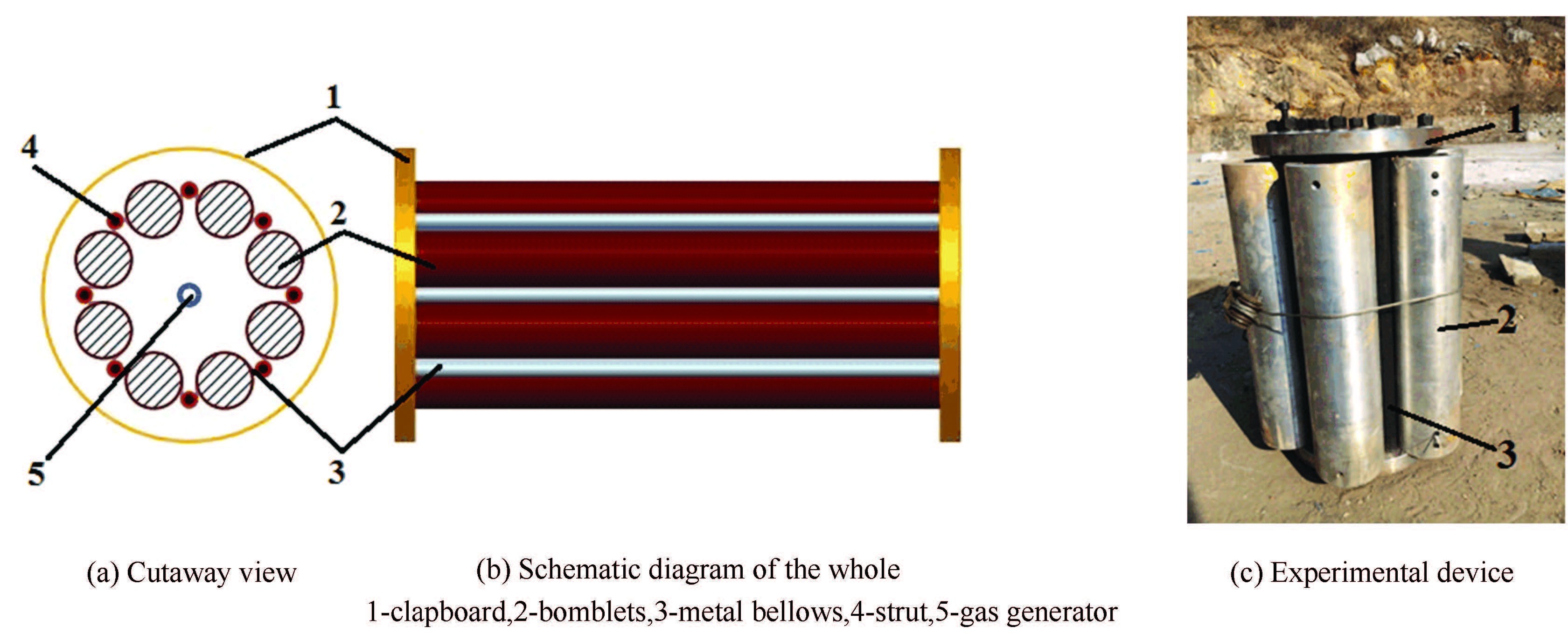 Figure 1 The system of the metal bellows inflating to disperse bomblets
 2.2 Model Simplification and Basic AssumptionsThe ignition,the propellant combustion and bellows’ inflation driven by the gas constitute the complexity of the disperse system. So in order to study and reveal the dynamic characteristics of the metal bellows deformation and the changing law of internal flow field simply,the following assumptions have been made in this paper:
1) Not considering the propellant combustion,and treat the interior ballistic parameters in the gas generator as the boundary conditions of the fluid equation.
2) Assuming the pressure distribution in the gas generator is uniform and the diaphragm breaks simultaneously.Because the nozzles on gas generator side are distributed evenly,they are simplified as a long and narrow seam according to the law of area equivalent.
3) Assuming the material model of the metal bellows is based on double linear constitutive relation. To neglect the influence of strain rates.
4) Assuming the process of the bellows inflating to disperse the bomblets driven by the gas is adiabatic,and the flow viscidity and the specific heat are constants.
3 Governing EquationIn this section,the governing equations for the fluid flow and the structure and the equilibrium conditions on the interface are described briefly. The boundaries of the fluid domain (Ωf) and structural domain (Ωs) are indicated as Sf and Ss. And the fluid-structure interface Si=Sf∩Ss is the common part of these boundaries.
3.1 Flow EquationIn this FSI calculation,the Navier-Stokes equations have to be solved on a moving mesh due to large deformation of the bellows. They are described in the arbitrary Lagrange-Eulerian formulation[15-17],given by
$\frac{\partial U}{\partial t}+w\cdot \nabla U+\nabla \cdot \left( F+G \right)=Q$ (1)
$p={{\rho }_{f}}\left( {{C}_{p}}-{{C}_{V}} \right)\theta \text{ }$ (2)
where:
According to the assumption (1),to calculate the interior ballistic equations described in the Ref.[1],and then apply the interior ballistic parameters in the gas generator to the boundary conditions of the fluid equation.
$\tau \cdot n=fS,\theta ={{\theta }^{S}},v={{v}^{S}} in{{{\bar{S}}}_{f}}\times \left( 0,\Gamma \right]$ (3)
where v and w,the velocity and relative velocity of the fluid flow,respectively; ρf,the fluid density; θ,the temperature; fb and qb,the body farce and heat quantity per unit of volume on the fluid,respectively; q,the capacity of heat transmission. For a Newtonian fluid,the stress tensor is defined as τ=-pI+σ with σ=2μe+λ?·vI,the shear stress tensor caused by the first and second viscosity dented by μ and λ,respectively. And e=1/2(?v+(?v)T) the strain rate of the fluid. vS,fS and θS are the prescribed velocity,tractions and temperature on the Sf.Γ is the time span considered,and t is time.
Eqs.(1)-(3) are discretized with FCBI scheme which is based on the Petrov-Galerkin variational formulation[17].
$\int_{\Omega }{Y}\left[ \frac{\partial {{U}^{\prime }}}{\partial t}+w\cdot \nabla {{U}^{\prime }}+\nabla \cdot {{F}^{\prime }}+{{G}^{\prime }}-{{Q}^{\prime }} \right]d\Omega =0$ (4)
Where:
$\begin{align} & Y=\left[ \begin{matrix} q \\ w \\ w \\\end{matrix} \right],{{U}^{\prime }}=\left[ \begin{matrix} \rho \\ \rho u \\ \rho {{C}_{V}}\theta \\\end{matrix} \right],{{F}^{\prime }}\left[ \begin{matrix} \rho +0 \\ \rho uv+pI \\ \rho {{C}_{V}}u\phi +up \\\end{matrix} \right]= \\ & {{G}^{\prime }}=\left[ \begin{matrix} 0 \\ -\sigma \\ -\sigma \cdot u+q \\\end{matrix} \right],{{Q}^{\prime }}=\left[ \begin{matrix} 0 \\ {{f}_{b}} \\ {{f}_{b}}\cdot u+{{\rho }_{f}}{{q}_{b}} \\\end{matrix} \right] \\ \end{align}$
In the FCBI scheme,the interpolation functions for the non-convection term are established with Galerkin method. And the trial functions which are based on the local Reynolds numbers (for velocity) and Peclet numbers (for temperature) are used to avoid the instability of convection term cause by high Reynolds and Peclet numbers.The detailed description of FCBI scheme refers to Refs.[15, 18].And the denotation in Eq.(4) is the same as that in Ref.[17].
3.2 Structural EquationThe deformation of the structure is determined in the Lagrange formulation.
${{\rho }_{s}}\frac{{{d}^{2}}{{u}_{s}}}{d{{t}^{2}}}+\eta \frac{d{{u}_{s}}}{dt}=\nabla \cdot {{\sigma }_{s}}+{{\rho }_{s}}{{f}_{s}}$ (5)
${{\sigma }_{s}}=D{{\varepsilon }_{s}}$ (6)
where us,the displacement of structure; ρs,the structure density;η,the damping coefficient;and fs,the body farce per unit of volume on the structure. According to the assumption (3),the relation between the stress tensor σs and strains tensor εs is given by Eq.(6) with elastic matrix D.
Also,the process of force transformed from the bellows to the bomblets is expressed by a couple of contrary forces tFA and t FB at any time.
$^{t}{{F}^{B}}={{-}^{t}}{{F}^{A}}$ (7)
In this paper,the finite element model of bellows is consisted of MITC elements,which is detailed in Refs.[19-20].The discrete equations for the structure are given by
$M\ddot{a}(t)+C\dot{a}(t)+Ka(t)=Q(t)$ (8)
where,?,
3.3 Iteration Method of FSI Dynamic ModelThe equilibrium conditions on the fluid-structure interface are the kinematic condition and dynamic condition[12, 16, 17].
$\underline{{{v}_{f}}}=\underline{{{{\dot{d}}}_{s}}},x,t\in {{{\bar{S}}}_{i}}\times \left[ 0,\Gamma \right]$ (9)
$\underline{{{f}_{f}}}=\underline{{{f}_{s}}},x,t\in {{{\bar{S}}}_{i}}\times \left[ 0,\Gamma \right]\text{ }$ (10)
The force on the nodes of bellows is mapped from fluid traction by
$\underline{{{f}_{s}}}=\int_{{{S}_{i}}}{{{H}_{s}}}{{{\hat{f}}}_{{\underset{\raise0.3em\hbox{$\smash{\scriptscriptstyle-}$}}{f}}}}ds$ (11)
where
The solution vectors corresponding to fluid domain and structure domain are defined as Xf and Xs,so the couple equations for FSI problem can be written concisely as
$F\left[ X \right]=\left( \begin{align} & {{F}_{f}}\left[ {{X}_{f}},\underline{{{d}_{s}}}\left( {{X}_{s}} \right) \right] \\ & {{F}_{s}}\left[ {{X}_{s}},\underline{{{f}_{f}}}\left( {{X}_{f}} \right) \right] \\ \end{align} \right)=0$ (12)
The iteration method[12, 14]is used to solve Eq.(12). Namely,the fluid equations and the solid equations are solved individually in succession,always using the latest information provided from another part of the coupled system.Although the coordinate systems used in the fluid and solid models are different,the displacement,velocity and acceleration are the same on fluid-structure interface where the Lagrangian coordinate system is used.Therefore,we firstly focus on the time integration on the interface and then apply the results to the whole computational domain.And the Newton-Raphson iteration is continued until the convergent of solution in every time step is acquired.
4 Numerical Solution of a Metal Bellows Inflating to Disperse Bomblets4.1 Finite Element ModelA 3D dynamical model of the metal bellows inflating to disperse bomblets driven by gas(W model) is established,and its geometry and mesh are shown in Fig. 2.The bellows thickness is 1 millimeter and each bomblets weights 5 kg.According to assumption (2),nozzles are simplified into 4 inlets,and the boundary conditions are applied as shown in Fig. 3. And the material properties of metal bellows and gas are shown in Table 1.The one-eighth finite element model is built on account of the symmetry of the structure. The bellows domain and the fluid domain are discretized with MITC9 and FCBI scheme.
Figure 2
 Figure 2 The 3D model of the metal bellows inflating to disperse bomblets
 Figure 3
 Figure 3 Boundary conditions on the inlet
 表 1
2070.322410.91.3318470.1678.13e-5
Table 1 Material properties in bellows inflating to disperse bomblets problem
4.2 Analysis of Calculation ResultsIn this section,the objective is to demonstrate and analyze the results of FSI problem in the process of a metal bellows inflating to disperse bomblets. The change history of the flow field and the stress/strain field is shown in Figs. 4-8. In order to state the history clearly,we can divide it into three stages.
Figure 4
 Figure 4 The distribution of pressure and velocity vector at different time
 Figure 5
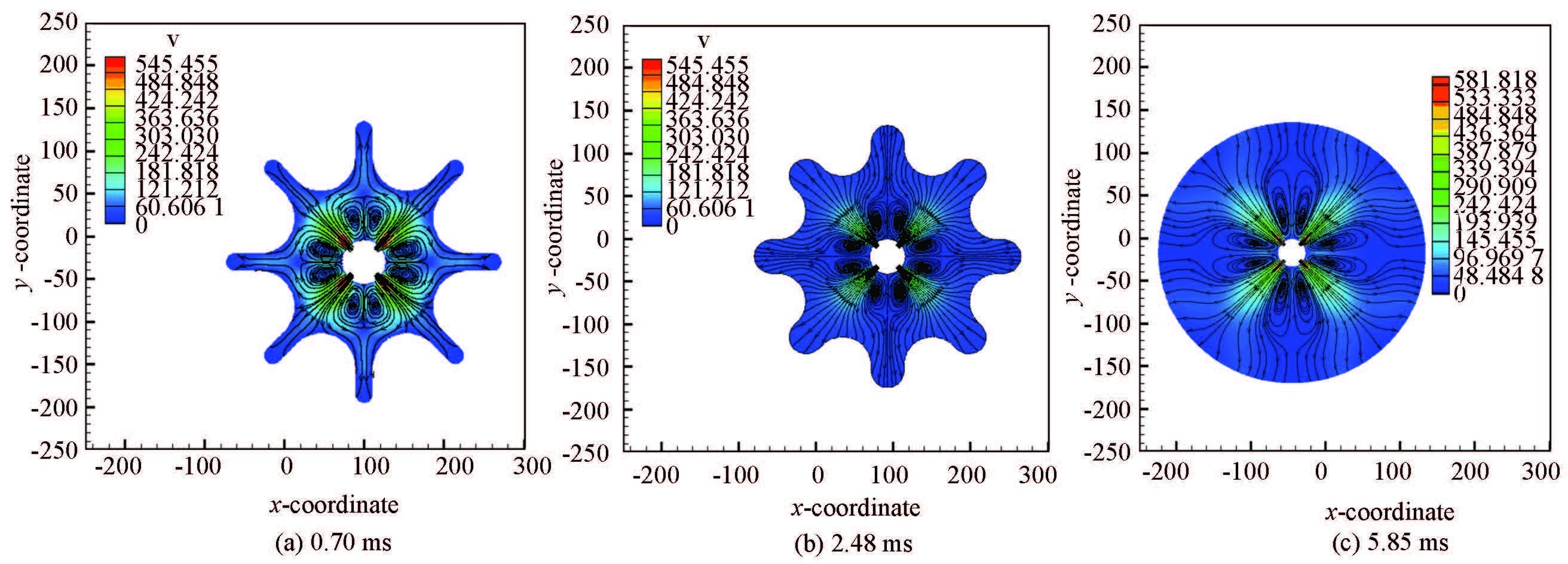 Figure 5 The streamline in the transverse plane at different time
 Figure 6
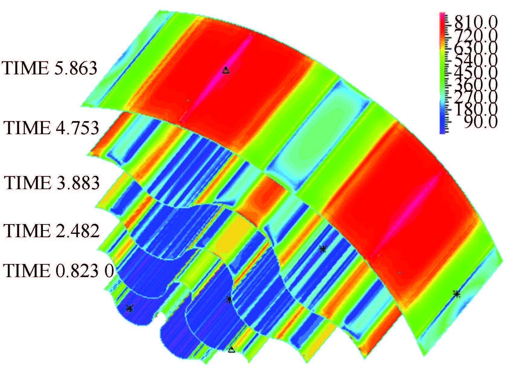 Figure 6 The distribution of stress at different time
 Figure 7
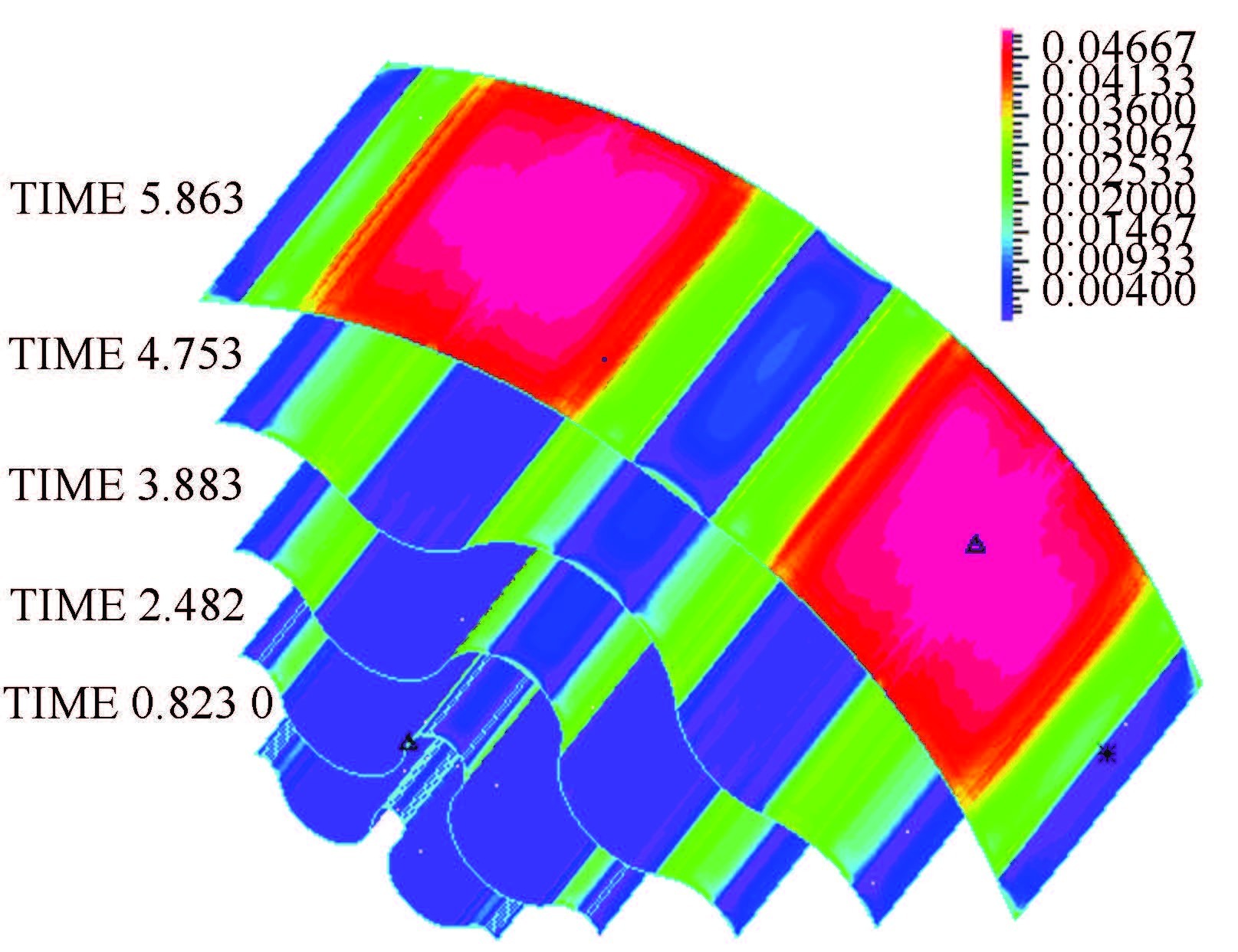 Figure 7 The distribution of strain at different time
 Figure 8
 Figure 8 Time-history curves of the stress at bellows’ different place in W model
 1) The stage of inflating with constant volume.
Because of the flexural rigidity of the bellows and the inertia of the bomblets,the volume of bellows cavity changes slightly in this stage. So we can define this period as the stage of inflating with constant volume. In this stage,the propellant gas,driven by high pressure,initially flows into the bellows cavity at local speed of sound. Therefore,the pressure in the cavity increases sharply. And the vortexes generate rapidly at the two sides of every nozzles as they squeeze mutually between the neighboring nozzles.Demonstrated as Figs. 6-8,the bellows' stress changes acutely and the maximum values appear at parts I and Ⅱ,while the strain varies small,less than 0.01.
2) The stage of geometric deformation.
This stage spans the end of stage one to the beginning of the stress/strain in bellows' part Ⅲ increases rapidly. Due to the large displacement of the bellows and the slight strain changing as shown in Fig. 7,we name this stage the geometric deformation. The stress of part Ⅱ is more complicated than that of parts I and Ⅲ on the account of the transformation among them. In the stage,the rapid increase of the volume in the bellows makes a peak fluid pressure,and the inlet velocity decreases with the pressure difference reducing around the nozzles. The vortex centers are essentially unchanged,but the vortex domain growing continuously,as shown in Figs. 3 and 4.
3) The last stage of inflating.
In this stage,the fluid pressure decreases to the minimum as the volume of bellows cavity tends to the maximum. The strain replaces the geometric deformation to be the dominant deformation mode. This stage ends at the moment of bomblets separating from the bellows with the maximum speed.
In W model,four points are picked to monitor the stress changing history at bellows' different place as shown in Fig. 8,and their places are demonstrated in Fig. 2(a). Because of the inertia of the bomblets,the stress at point D changes small until the stage two ends. Furthermore,the stress forms at points A,B and C are different because of the bending deformation and the large displacement of the bellows.
We take point C as an instance to analyze its stress changing process (stress-C)as shown in Fig. 8.The fluid pressure tenses part Ⅱ at initial time,and then bends it to force the tensile stress at point C to be compressive stress. In this period,point C is moved into part Ⅲ. So the stress decreases at the moment of 1.38 ms.Due to the movement of bomblets and the growth of bellows' displacement,the geometric constrain that the bomblets gives to the bellows reduces and the part Ⅱ extends while part Ⅲ shrinks. When point C is outside of part Ⅲ,its stress recovers to be tensile stress.The stress reaches its peak at the time 3.68 ms as point C locates the center of bent part Ⅱ,and then decreases persistently until the stage three is coming.
The above analysis of the flow field and stress/strain field are credible and reasonable,because the fluid pressure acting on the bellows and the bomblets'motion law achieved from the W model and interior ballistic model are approximate greatly,as shown in Figs. 12-15. They prove the correctness of the FSI model built in this paper and the accuracy of its result.
The results of the above content in this section are based on W model which ignores the existing of gaps at both ends of fluid domain. In order to analyze the influence what the gaps brings to the fluid filed and the motion law of bomblets,the FSI dynamic model containing gaps(Y model) is built and simulated. Its boundary conditions are the same as those in W model,except the gaps. The 1/8 fluid computational domain with a 2 mm wide gap is demonstrated in Fig. 10.
Some conclusions are achieved by comparing the results of the two models. Firstly,for Y model,although the existence of the gap enhances the pressure gradient around it,the pressure distribution of the whole fluid domain as shown in Fig. 11 is uniform as that of W model. Four points are selected along axial directionas shown in Fig. 10 to monitor the pressure on the interface. This conclusion is also proved by comparing the pressures at these points as shown in Fig. 12 which presents that the pressures outside the gap are especially approximate. Secondly,what present in Figs. 8 and 9 is that the stress variations of two models are almost the same in the process of the bellows inflating,but the stress of Y model reduces slight as the fluid pressure acting on the bellows decreases.Thirdly,just as shown in Figs. 13 and 14,the bomblets'separation speed and the overload of Y model are reduced by about 10% and 30% due to the leakage of the gas power from the gap,respectively. And what the displacement curves of the bomblets in both models presented in Fig. 15,transmit is that the disperse time in Y model is longer than that of W model under the same displacement.Above all,the existence of the gaps changes the distribution of the flow field and the stress/strain relatively small,but obviously reduces the bomblets'separation speed which is one of the key purposes of this dispersion system.
Figure 9
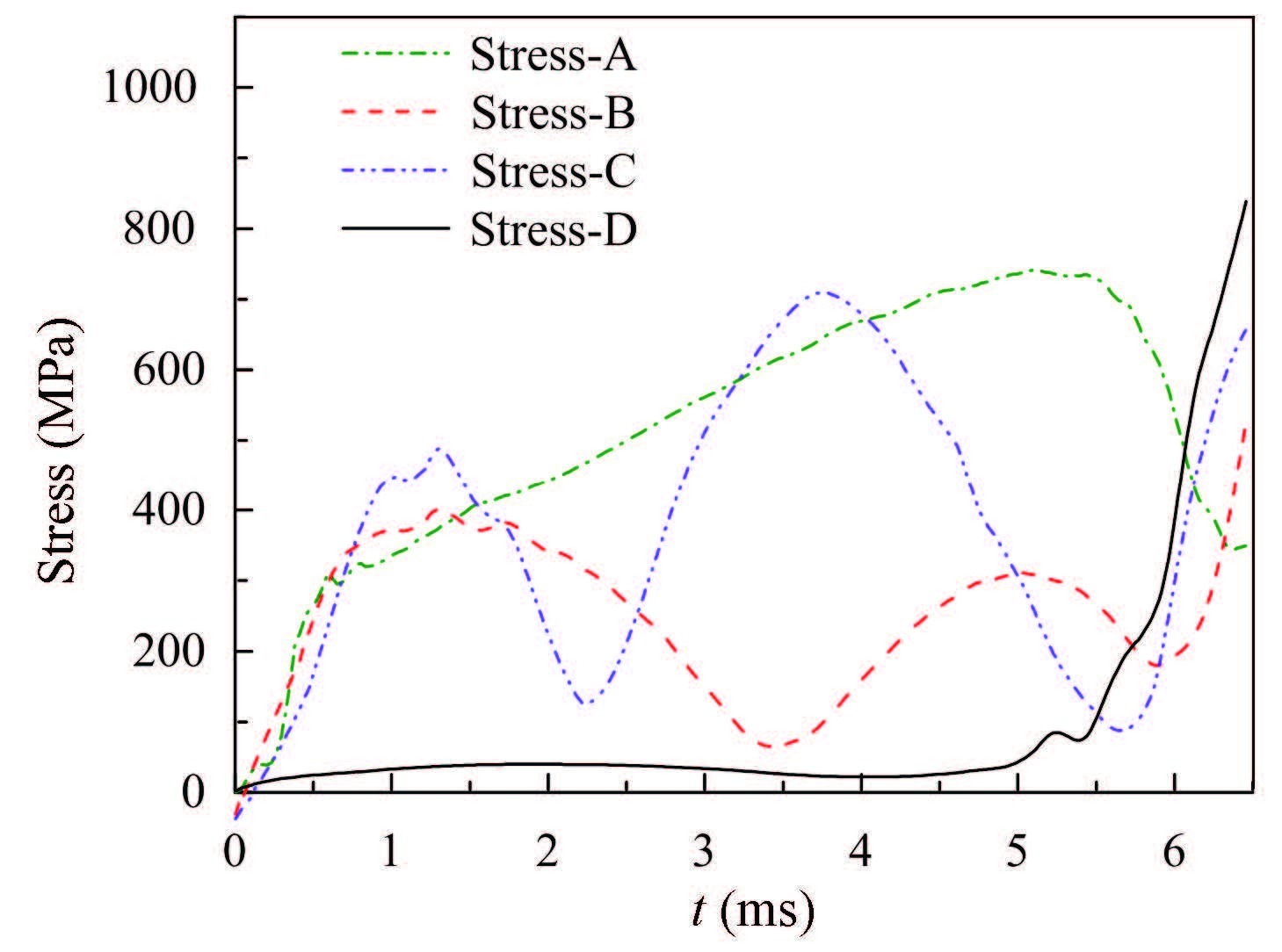 Figure 9 Time-history curves of the stress of bellows’ different part in Y model
 Figure 10
 Figure 10 The 1/8 geometry of fluid domain in Y model
 Figure 11
 Figure 11 The distribution of pressure and velocity vector at different time in Y model
 Figure 12
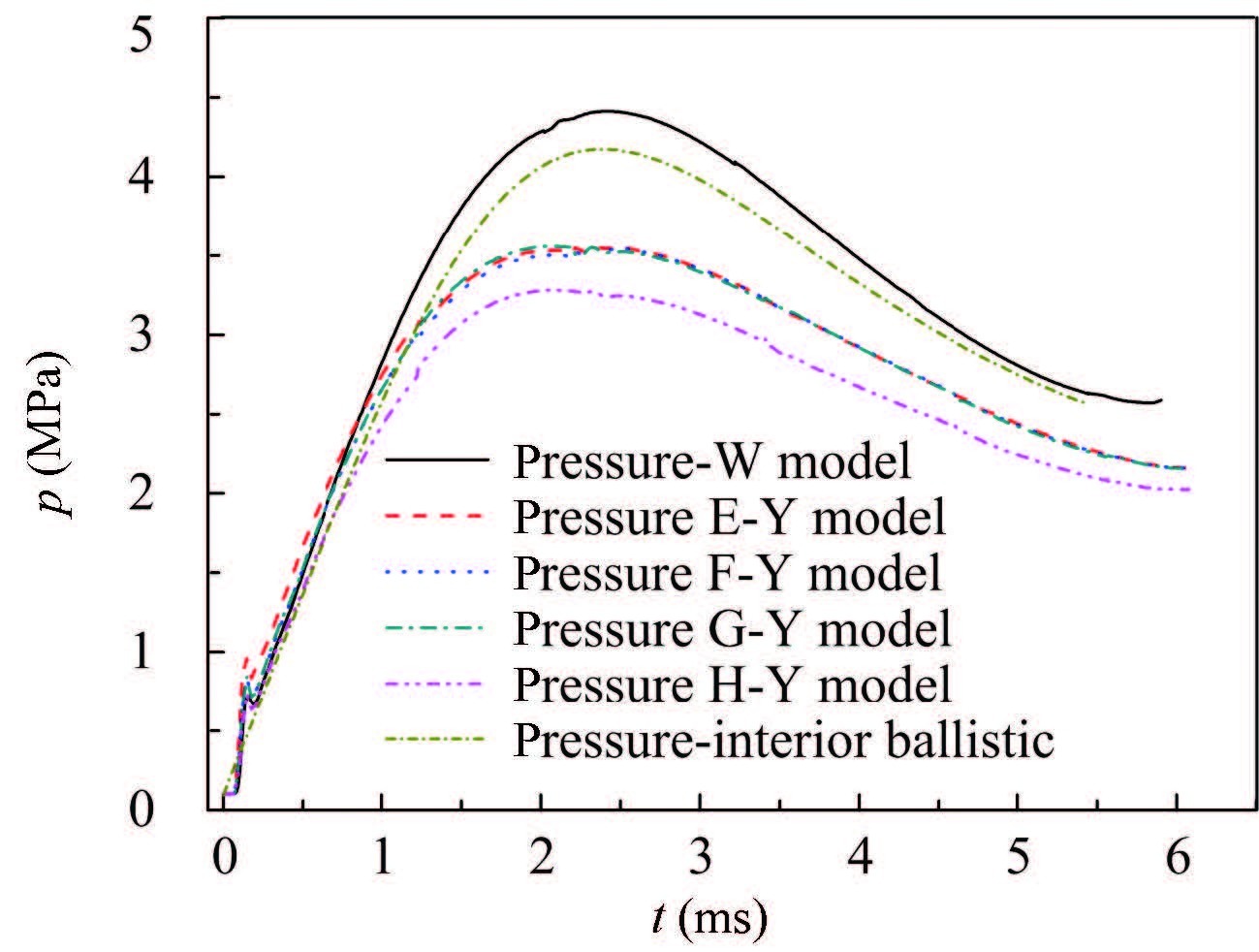 Figure 12 Time-history curves of the fluid pressure acting on the bellows
 Figure 13
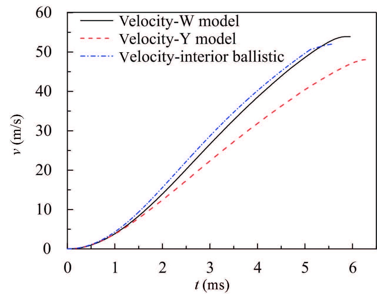 Figure 13 Time-history curve of the bomblets’ velocity
 Figure 14
 Figure 14 Time-history curve of the bomblets’ acceleration
 Figure 15
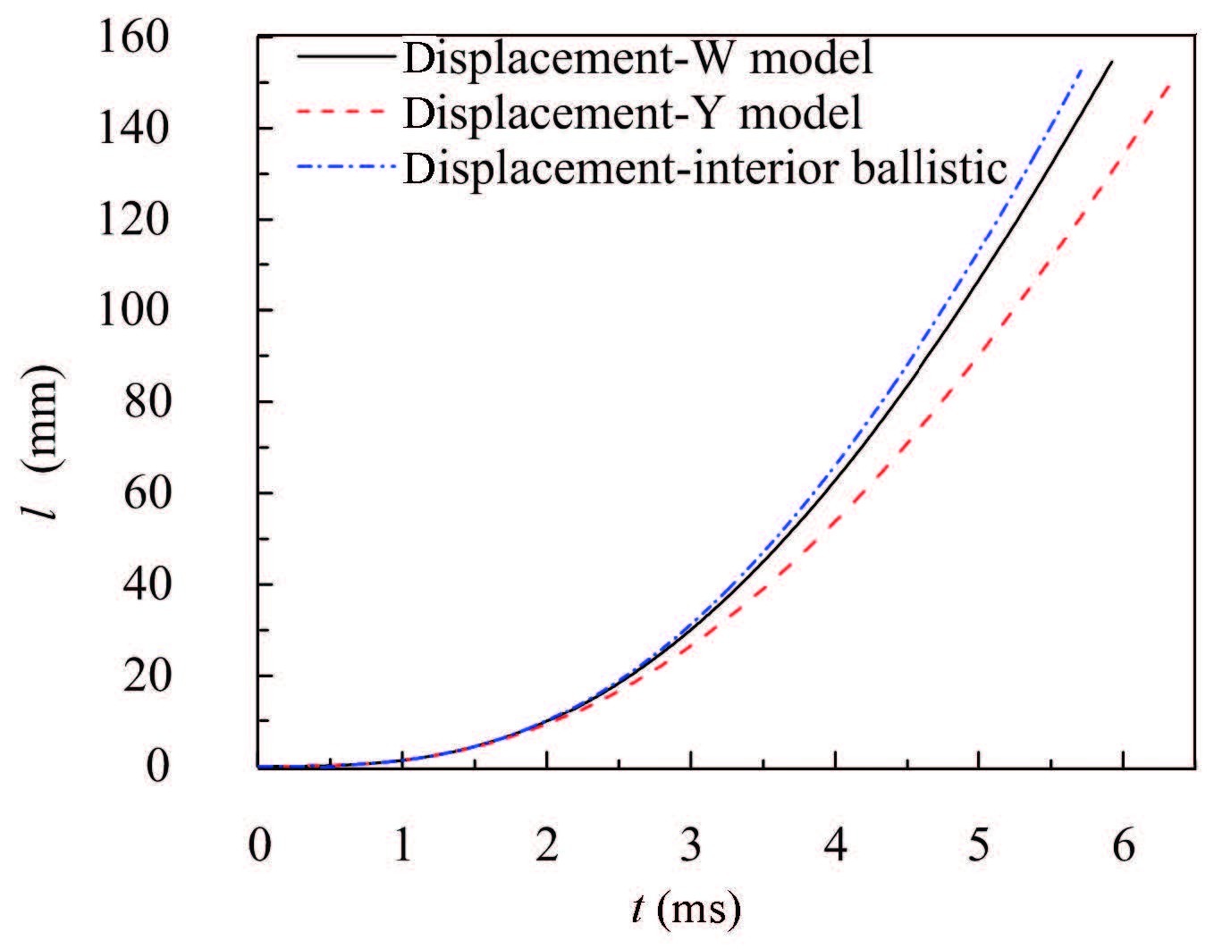 Figure 15 Time-history curve of the bomblets’ radial displacement
 5 ConclusionsAccording to the characteristics of fluid-structure interaction in the process of a metal bellows inflating to disperse bomblets,a FSI method of calculating the interaction between a viscous compressible flow and a structure undergoing large deformations is introduced. And a 3D dynamical model of the metal bellows inflating to disperse bombs is established and simulated. The following conclusions are drawn:
1) It is stable and effective that the structure equations and fluid equations of the FSI model in this paper are discretized with the MITC scheme and FCBI scheme,respectively. The dynamic characteristics of the metal bellows deformation,the changing law of the internal flow field and the motion law of the bomblets are acquired by employing this coupling method to simulate the process of a metal bellows inflating to disperse bomblets driven by gas. And comparing these results with the interior ballistic results,the correctness of the FSI model is proved.
2) In the process of dispersing,the results show that the pressure distribution in the bellows cavity is more uniform,apart from that around the inlet. The stress changing histories at the bellows’ different place are achieved,and the moment and location of the maximum stress/strain are also acquired. These results provide an effective theory and reference for the engineering design and application in bellows inflating to disperse bomblets.
3) The existence of the gaps influences the fluid field and the structure deformation slightly,but reduces the separation speed of the bomblets by comparing the results of W model and Y model. So in order to obtain the sufficient the separation speed of the bomblets,the gaps should be as small as possible or the import flow rate should be supplemented in the design of gas generation system.
References
[1]Xu Wenxu, Zhang Jing, Qi Zhanyuan. The modeling and simulation of interior trajectory forcluster munition dispersing.Acta Armamenttarii,2006, 27(5): 797.(
 0)
0)[2]Wang Xinjian, Jiang Wenhao. Interior Ballistic Parameters of Submunition Dispensers.Beijing:BeijingInstitute of Technology Press,1994, 14(4): 378-384.(
 0)
0)[3]Sun Xinli, Cai Xinghui, Wang Shaolong. The static experiment of opening cabin to disperse cluster bombs.Acta Armamentarii,2002, 23(2): 258-260.(
 0)
0)[4]Zhang Bozi, Wang Shanshan, Huang Bei, et al. Influence of spoiler on overturning angular rate of submunition.Journal of Nanjing University of Science and Technology,2015(1): 7-14.(
 0)
0)[5]Zhang Bozi, Wang Hao, Wang Shanshan. Dispensing interior ballistic numerical simulation on cluster bomb of center powder gas.Journal of Ballistics,2014(3): 23-27.(
 0)
0)[6]Yu Li, Chen Han, Liu Xiong. Numerical simulation of airbag during deploying process.Journal of Nanjing University of Aeronautics&Astronautics,2010, 42(4): 472-476.(
 0)
0)[7]Zhang Sheng, Cheng Han, Liu Xiong, et al. Study on flow field characteristics of airbag deploying process.System Simulation Technology & Application,2011, 13: 116-120.(
 0)
0)[8]Dai Xiaofang, Zong Zhi, Wang Xijun, et al. A comparative study on the CV and ALE methods forsimulating folded airbag deployment.Automotive Engineering,2008, 8(30): 676-680.(
 0)
0)[9] Mestreau Eric, Rainald Lhner. Airbag simulation using fluid/structure coupling.The 34th Aerospace Sciences Meeting & Exhibit.Washington, D.C.:AIAA, 1996.AIAA-96-0798. (
 0)
0)[10] Wei Jianzheng. Research on Gas-Solid Interaction Probleminthe Inflatable Deployment Process of Space Folded Membrane Boom. Harbin:Harbin Institute of Technology, 2008. (
 0)
0)[11] Salama M, Kuo C P, Lou M. Simulation of deployment dynamics of inflatable structures. Proceedings of the 40th AIAA/ASME/ASCE/AHS/ASC Structures,Structural Dynamics,and Material Conference.Reston, VA:AIAA, 1999.AIAA-99-1521. (
 0)
0)[12]Bathe K J. Finite Element Procedures.Prentice Hall,2006: 672-691.(
 0)
0)[13] Zhang H, Bathe K J. Direct and iterative computing of fluid flows fully coupled with structures.Proceedings of first M.I.T. Conference on Computational Fluid and Solid Mechanics.Amsterdam:Elsevier Science, 2001.1440-1443. (
 0)
0)[14]Degroote J, Bathe K J, Vierendeels J. Performance of a new partitioned procedure versus a monolithic procedure in fluid-structure interaction.Computers & Structures,2009, 87(11/12): 793-801.(
 0)
0)[15]Kohno H, Bathe K J. A flow condition based interpolation finite element procedure for triangular grids.International Journal for Numerical Methods in Fluids,2006, 51(6): 673-699.(
 0)
0)[16]Bathe K J, Zhang H, Wang M H. Finiteelement analysisofin compressible and compressible fluid flows with free surfaces and structur alinteractions.Computers & Structures,1995, 56: 193-213.(
 0)
0)[17]Bathe K J, Zhang H. Finite element developments for general fluid flows with structural interactions.International Journal for Numerical Methods in Engineering,2004, 60(1): 213-232.(
 0)
0)[18]Bathe K J, Pontaza J P. A flowconditionbased interpolation mixed finite element procedure for higher reynolds number fluid flows.Mathematical Models and Methods in Applied Sciences,2002, 12(4): 525-539.(
 0)
0)[19]Bathe K J, Zhang H. Finite element developments for general fluid flows with structural interactions.International Journal for Numerical Methods in Engineering,2004, 60(1): 213-232.(
 0)
0)[20]Chapelle D, Bathe K J. The Finite Element Analysis of Shells: Fundamentals.Berlin: Springer, 2003: 326-336.(
 0)
0)[21]Lee Phill-Seung, Bathe K J. Insight into finite element shell discretizations by use of the “basic shell mathematical model”.Computers & Structures,2005, 83: 69-90.(
 0)
0)