 ,?Department of Physics and Atmospheric Lidar Institute, Civil Aviation Flight University of China, Guanghan 618307, China
Corresponding authors: ?E-mail:fbinyang@qq.com
Received:2019-03-12Online:2019-08-1
| Fund supported: |

Abstract
Keywords:
PDF (1450KB)MetadataMetricsRelated articlesExportEndNote|Ris|BibtexFavorite
Cite this article
Fu-Bin Yang. Aharonov-Bohm Interferometer in a T-Shaped Quantum Dot Embedded in Majorana Bound States *. [J], 2019, 71(8): 1024-1028 doi:10.1088/0253-6102/71/8/1024
Majorana fermions have recently materialized in condensed matter systems for the feature to be theirown anti-particles.[1-3] A Majorana fermion can be seen as a half common fermion, and a pair of non-locally distributed Majorana fermions is always present in pairsat the ends of the topological nanowire, which generates associations through non-local Fermi states. Ever since the first experimental observations,[4] the interesting properties involving Majorana bound states (MBS) have included the detection and manipulation of these states to explore quantum entanglement.[5] One of the exciting and promising branches in this context is the study of the interplay between MBSs and quantum dots (QDs).[6-7]When MBSs are coupled to QDs, they will superimpose new interference on the original quantumcoherence pattern.[8-9] When the parameters in hybridized QD-MBS are properly adjusted,a special Fano effect and other oscillation curves will appear.[10-11] Motivated by the success in fabricating the hybridized QD-MBS system, the MBS-assisted transport properties in the Aharonov-Bohm (AB) ring have also attracted much interest,[12-13]indicating the feasibility to manipulate the current by means of the hybridized QD-MBS coupling. In an AB ring, the current shows periodicity on the flux $\Phi$ enclosed by the AB ring. The currentwill show oscillation behavior with the change of the local magnetic flux when the finite magneticflux threads on the ring.[14]
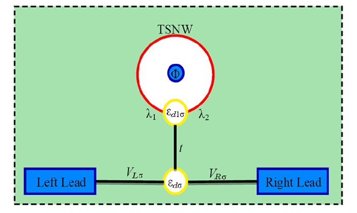
In this work, we introduce an AB interferometer between two topological MBSs attheir ends, via the conductance across a QD embedded between ferromagnetic leads as shownin Fig. 1. The designed geometry of the device exploits the high phase sensitivity of the conductance. As such, it can be seen as an example of the elemental unit of complexlogical qubit architectures.[15] To address this problem, we consider an effectivelow energy Hamiltonian and solve the system using an equation of motion method. Our results show that the interaction of QD-MBS is manifested in the observation of conductance through han AB interferometer. We also discuss how the presence of leads spin polarization strength affects the conductance resonances that give rise to the interesting conductance behaviors.
Fig. 1
 New window|Download| PPT slide
Fig. 1(Color online) Schematic setup of the Aharonov-Bohm (AB) interferometerdiscussed in the paper. A T-shaped quantum dot (QD) is coupled to two ends of a 1D toplogicalsuperconductor nanowire (TSNW) to form an AB ring by the coupling strength $\lambda_{1(2)}$. $\Phi$is the phase resulting from the magnetic flux threading around the AB ring. tdescribes the coupling between QD$_1$ and the central QD, which is connected with theferromagnetic (FM) leads through the tunnel matrix elements $V_{\alpha \sigma}(\alpha=L,R)$.
Hence, the Hamiltonian can be written as
$H_{\rm DQD} =\sum\limits_\sigma {\varepsilon _{d\sigma } d_\sigma ^ + d_\sigma }+ \sum\limits_\sigma {\varepsilon _{d1\sigma } d_{1\sigma }^ + d_{1\sigma } }+ \sum\limits_\sigma {(td_{1\sigma }^ + d_\sigma + d_\sigma ^ + d_{1\sigma } )}$$+ \sum\limits_{k\alpha ,\sigma } {\varepsilon _{k\alpha \sigma } c_{k\alpha \sigma }^+ c_{k\alpha \sigma }^{} } + \sum\limits_{k\alpha ,\sigma } {(V_{\alpha \sigma } c_{k\alpha \sigma }^+ d_\sigma^{} + {\rm h.c.})}$ describes the T-shaped QDs where one central QD connects with the ferromagnetic (FM) leads.$t$ describes the coupling between the two QDs.$V_{\alpha \sigma }$ is the tunnel matrix elements, which can be rewritten byan effective line width function $\Gamma _\sigma ^\alpha = \pi \sum\limits_{k\alpha \sigma }{\left| {V_{\alpha \sigma } } \right|^2 \delta (\varepsilon - \varepsilon _{k\alpha \sigma } )}$.Here, the spin polarization strength can be introduced by an effective definition as$p = (\Gamma _\sigma ^\alpha - \Gamma _{\bar \sigma }^\alpha )/(\Gamma _\sigma ^\alpha+ \Gamma _{\bar \sigma }^\alpha )$. We can then introduce $\Gamma _{ \uparrow \downarrow }^L= \Gamma _{ \uparrow \downarrow }^R = (1 \pm p)\Gamma _0^{} $ for the parallel (P)configuration and $\Gamma _{ \uparrow \downarrow }^L = \Gamma _{ \downarrow \uparrow }^R= (1 \pm p)\Gamma _0^{} $ for the antiparallel (AP) configuration, where $\Gamma _0 $is the value at p=0 and sets to be the unit in our numerical results.$H_{\rm MB} {\text{ = }}\varepsilon _M (f_M^ + f_M - ({1}/{2}))$ is the Majoranawire Hamiltonian with $\varepsilon _M$ the splitting overlap with $\varepsilon _M$$\propto \exp[-{L}/\ell$], where L is the length of the wire and $\ell$ the superconducting coherence length. $f_M (f_M^ + )$ is the regular fermion operatorsafter the replacement of the Majorana fermion operators.
represents the coupling between QD$_1$ and the MBSs in the new representation.We assume that the QD$_1$ is symmetrically coupled to the two MBSs to constitute anAharonov-Bohm ring. We then set $\lambda _1 = \lambda e^{i\phi/4} ,\lambda _2 =\lambda e^{ -i\phi /4}$, where $\lambda$ denotes the respective QD-MBS coupling strength and $\phi = \Phi /\Phi _0 (\Phi _0 = h/2e)$ is the phase factor resulting from thethreading magnetic flux. It is valid to note that the currents presented in the systemcan be derived by the time-dependent evolution of the electron number in the left lead.We can further derive the Landauer current formula of this system
where $f_{L(R)} (\varepsilon )$ is the Fermi distribution function of the left (right) lead and $T_\sigma(\varepsilon )$ is the transmission probability per spin given by$T_\sigma (\varepsilon ) = {{\Gamma _\sigma ^L \cdot \Gamma _\sigma ^R }}/{({\Gamma _\sigma ^L+ \Gamma _\sigma ^R })}\operatorname{Im} \langle\langle d_\sigma ^{} ,d_\sigma ^ + \rangle\rangle $.From which, the zero-temperature conductance is found to be
Thus the calculation of conductance requires the retarded dot Green function.From the equation of motion method,[16]we have the explicit derivations of the dot Green function as follows
where $A = (\varepsilon - \varepsilon _{d1\sigma } ) - k_1 - k_2$ and $B = [(\varepsilon- \varepsilon _{d1\sigma } ) + {{t^2 }}/({{\varepsilon + \varepsilon _{d\sigma } - \sum\nolimits_{0\sigma }^r {(\varepsilon )} }})]- k_1 + k_2 \cos ({\phi }/{2})$.$k_1$, $k_2$ are defined as $k_1 = {{{\text{2}}\lambda ^{\text{2}} \varepsilon }}/{{(\varepsilon ^2 - \varepsilon _M^2 )}}, k_2 = {{{\text{2}}\lambda ^{\text{2}}\varepsilon _M }}/{{(\varepsilon ^2 - \varepsilon _M^2 )}}$ and $\sum\nolimits_{0\sigma }^r {(\varepsilon ) = }(- {i}/{2})(\Gamma _\sigma ^L + \Gamma _\sigma ^R )$.For simplicity, we set the energy level ofthe dot as ${\varepsilon _{d\sigma }=0 }$, ${\varepsilon _{d1\sigma }=0 }$.The overlap of the two MBSs is chosen as ${\varepsilon _{M }=0.5 }$.In order to investigate the Aharonov-Bohm interferometer effect on the period change,we choose a specific value for $eV = 0.5$. The parameters we chose are sufficient to describeall the transport properties of this system even though when we choose other values.
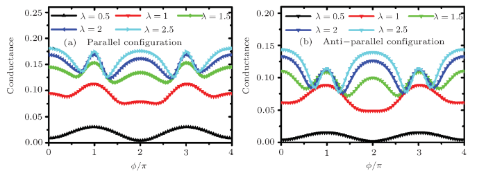
In the next section, we are going to give the numerical conductance results under differentspin polarization as well as the QD-MBS coupling strength. We first discuss the total conductance as afunction of $\phi$ with different QD-MBS coupling strength ($\lambda$) under parallel and anti-parallelconfiguration in Fig. 2. The conductance exhibits the periodic structure of $4\pi$, which originates from the protection of the $4\pi$ periodicity if the entire ring is topologicallynontrivial.[17] In the case of $\phi=\pi$ or $\phi=3\pi$, we see a significant resonancestate no matter how strong the coupling strength is. However, the conductance shows different propertiesat $\phi=2\pi$. It is an anti-resonant structure at low coupling strength while a resonance structureat large coupling strength. As the coupling strength ($\lambda=1$) increases, the conductance willgradually become a platform structure from the cornice. Even it will completely become a resonantstructure when the coupling strength is further increased ($\lambda>1.5$). It is foreseeablethat the conductance increases with the increase of $\lambda$.In the same coupling case, the conductance in the parallel configuration is significantlylarger than that in the antiparallel configuration, leading to a relatively pronounced spinvalve effect. As the QD is strongly coupled to the nanowire, the phases of those electronsthrough the QD going into the nanowire will experience a swift phase changing (almost a $\pi$ phase changing).Thus the electrons through different paths will interfere with each other from destructively to constructivelyor vice versa. In order to better explain the relationship between the conductance of the system and thecoupling strength, we next describe the specific up- and down-spin transportrelationship to explain why the above transport properties occur.
Fig. 2
 New window|Download| PPT slide
Fig. 2(Color online) The total conductance as a function of $\phi$ with different QD-MBS coupling strength under parallel and anti-parallel configuration, the other parameters are chosen as $p=0.6$, $t=2$.
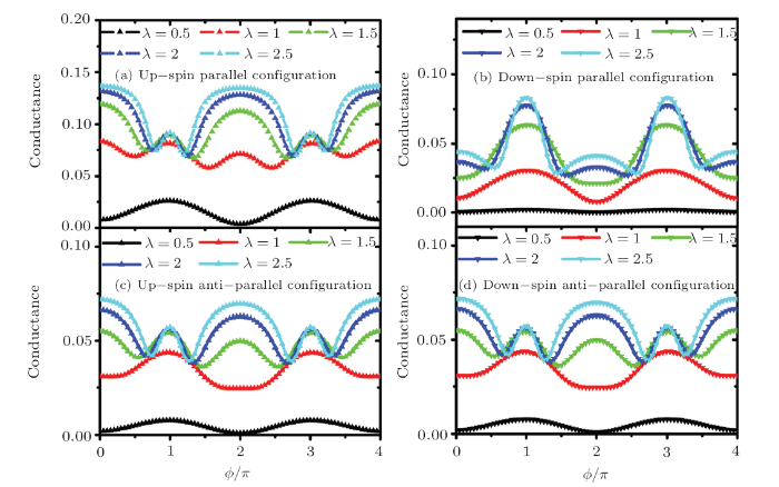
The explicit up- and down-spin transport properties under parallel configuration are shown in Figs. 3(a)and 3(b). The up-spin conductance shows a more obvious formant structure, which appears at $\phi=\pi$ and$\phi=3\pi$ with the increasing $\lambda$. However, it first appears to a valley structure and laterthe peak structure at $\phi=0,2\pi,4\pi$ and $\phi=3\pi$ with the increasing $\lambda$. For the down-spinconductance, we see that the value of conductance is much smaller than that of the up-spin at the samecoupling strength. As the coupling strength increases, the conductance at $\lambda=1$ does not show apeak structure, and the valley structure is still exist, which is inconsistent with the up-spin situation.Moreover, the critical coupling strength from the cornice to the peak structure is at $\lambda>1.5$.Due to the compensation effect on the up-spin and down-spin, we can then conclude that why the totalconductance exhibits a platform structure. It has been demonstrated in the QD-AB ring systemthat the phase acquired by electrons traversing the QD increases smoothly by $\pi$ along aresonance peak.[18] The $\cos ({\phi }/{2})$ and $\sin ({\phi }/{2})$ partin the denominator of the green function is corresponding to 0 and 1 respectively at $\phi=\pi$ or$\phi=3\pi$ when the coupling strength is small, which gives rise to the minimum of the denominatorof the Green's function at this time, so the conductance should present a maximum. When $\phi$ transitsto $2\pi$, the $\cos ({\phi }/{2})$ and $\sin ({\phi }/{2})$ part exactly happens to reverse.So the conductance is minimal, which is the opposite of $\phi=\pi$ and $\phi=3\pi$. The reason forthe differences originates from that the Majorana fermions appearing at the end points of eachsegment are represented by anticommuting Hermitian operators, which they represent mixtures ofparticle and hole states. Thus, at $\phi=\pi,3\pi$, the zero energy modes will show up in theA-B ring system while there will be no Majorana zero energy modes when $\phi=0,2\pi$. The electronictransport properties show different behaviors for these two different situations, basing on whetherthere are zero energy modes (or MBSs) in this system.
Fig. 3
 New window|Download| PPT slide
Fig. 3(Color online) The up- and down-spin conductance as a function of $\phi$ with different QD-MBS coupling strength under parallel configuration ((a) and (b))and anti-parallel configuration ((c) and (d)), the other parameters arechosen the same as that in
Next we show the explicit up-and down-spin conductance under anti-parallel configurationin Figs. 3(c) and 3(d). The up-spin conductance shows identical characteristicswith the down-spin conductance in all, which comes from the same DOS in the lead underanti-parallel configuration. In the case of a small coupling strength, the conductanceexhibits a small value at $\phi=0,2\pi$, and the maximum value at the $\phi=\pi,3\pi$,which increases with the coupling strength. It turns out that the minimum at $\phi=0,2\pi$becomes a maximum, which is consistent with what we see in the parallel configuration state.The difference is that such a transition is exhibited at $\lambda>1$ under the parallel reluctance state.It is clear that the transition in the antiparallel configuration results in a smaller conductance valuefor the contribution to the total conductance.
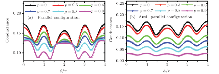
We then study the curve of total conductance with different spin polarization strength p in Fig. 4.In the parallel configuration, the maximum value is presented at $\phi=n\pi$ and a minimum at $\phi=\pi/2,3\pi/2$,when the spin polarization coefficient is relatively small. The peak value decreases as p increases.From the perspective of $\phi$, it shows the same results as the previous chapter. The position of the minimumvalue increases with the increase of p. The special case is that a more obvious platform structureappears at the original maximum value if p is large enough $(p =0.9)$. In the antiparallelconfiguration state, the conductance decreases as $p$ increases. The peak structure is also quenched,and in the case of $p=0.9$, the peak structure appears almost completely annihilated. Nevertheless,we observe the properties somewhat analogous to the case of the parallel configuration. The conductancedecreases monotonically for the increase of p, which means that p does not only changethe resonance position of the conductance but also shifts its value.
Fig. 4
 New window|Download| PPT slide
Fig. 4(Color online) The total conductance as a function of $\phi$ with different spinpolarization strength under parallel and anti-parallel configuration, the other parameters arechosen as $\lambda=1.5$, ${t}=2$.
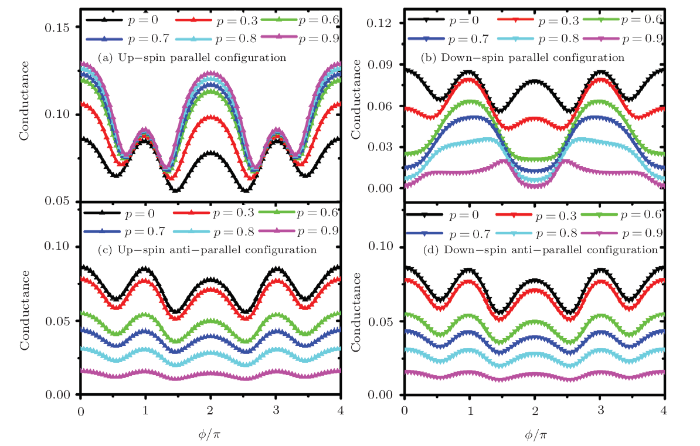
We last study the explicit up-spin and down-spin properties under parallel configuration in Figs. 5(a)and 5(b). The conductance increases as p increases, which indicating that the up-spin dominatesthe main transport properties at this time. We specifically analyze why it increases with the increaseof p. The peak structure appears at $\phi=n\pi$, presenting the transport characteristics consistentwith the previous ones in terms of transport characteristics with minimum values. On the contrary,the down-spin will decrease as p increases. The peak structure around $\phi=2\pi$ still exists whenp is small (p < 0.3), but the peak structure will weaken and become a minimum valueas p further increases. The structure of the cornice will become extremely small with the furtherincrease of p. and the peak structure also decreases as p increases.
Fig. 5
 New window|Download| PPT slide
Fig. 5(Color online) The up- and down-spin conductance as a function of $\phi$with different spin polarization strength under parallel configuration ((a) and (b))and anti-parallel configuration, the other parameters are chosen the same as thatin
The peak structure is weakenas p increases and eventually disappears at $\phi=\pi,3\pi$. The density of the statesin the leads that the spin-up is larger than the spin-down one with the increasing pin the parallel configuration, namely $\rho_{L\uparrow}+\rho_{R\uparrow}>\rho_{L\downarrow}+\rho_{R\downarrow}$,which makes the enhancement for the up-spin conductance and the recession for the down-spin transmission.Finally, we analyze the transport characteristics in antiparallel configuration in Figs. 5(c) and 5(d).In addition to the specific transport characteristics equal to the optional, the conductance will furtherdecrease as $p$ increases. For the antiparallel case, the current magnitude will also be enhanced for thesame reason. But the current spin polarization is irrelevant to the tunnel process through the bridgesince $\rho_{L\uparrow}+\rho_{R\uparrow}=\rho_{L\downarrow}+\rho_{R\downarrow}$,and up-spin electrons make the same contribution to the transmission probability as down-spinelectrons behave. Nevertheless, the increasing p can still help to reduce the transport probabilityof the up-and down-spin electrons, so we find the magnitude of the conductance decreases with theincreasing p, for the magnetization of electrodes suppresses the Kondo resonance in thissystem.[19]
In conclusion, we have studied the spin-dependent transport properties in the T-shaped Aharonov-Bohminterferometer under parallel and anti-parallel lead alignment. The conductance exhibits $4\pi$periodical dependence on the phase factor of AB ring. The conductance increases with the QD-MBScoupling strength, as well as a transition from resonance to anti-resonance at $\phi=2\pi$when the MBS-QD coupling strength changes from small to large. Besides, both the up-spin andthe down-spin conductance decrease with the increasing spin-polarization strength but for thedown-spin resonance annihilation when p is large enough. However the contribution ofthe up- or down-spin conductance is always identical with each other for the anti-parallelconfiguration. The understanding gained from our work will be helpful for the ongoing experiments,which is also helpful in describing the transport characteristics of the junction with hybridizedQDs and MBSs.
Reference By original order
By published year
By cited within times
By Impact factor
[Cited within: 1]
[Cited within: 1]
[Cited within: 1]
[Cited within: 1]
[Cited within: 1]
[Cited within: 1]
[Cited within: 1]
[Cited within: 1]
[Cited within: 1]
[Cited within: 1]
[Cited within: 1]
[Cited within: 1]
[Cited within: 1]
[Cited within: 1]
[Cited within: 1]
[Cited within: 1]
[Cited within: 1]
[Cited within: 1]
