Key Laboratory of Materials Modification by Laser, Ion and Electron Beams of Ministry of Education, School of Physics, Dalian University of Technology, Dalian 116024, China
Fund Project:Project supported by National Key R&D Program of China (Grant No. 2017YFE0301206)
Received Date:31 August 2019
Accepted Date:04 November 2019
Published Online:05 February 2020
Abstract:The coaxial gun plasma generated by pulsed discharge possesses the characteristics of high speed and high density, and has potential application value in the field of fusion, space propulsion and astrophysics. In this paper, the effect of positive and negative pulsed discharges on plasma characteristics are investigated and a theoretical model for analyzing the morphology of positive and negative pulsed current sheets is proposed. Positive and negative pulsed discharges are realized by changing the direction of the rectifier diode in the pulse power supply to change the direction of the recharging current. Through theoretical analysis, and measurements by using photodiode, Pearson probe, magnetic probe, HD camera, fast-framing camera and RGB image processing, the plasmas generated by positive and negative pulsed discharges are compared and investigated. Most of experimental diagnoses concentrate on investigating the plasma behavior in the coaxial gun muzzle on a microsecond-order time scale. Because radial and axial transport characteristics of plasma change little, we think, the plasma characteristics in the muzzle still depend on the characteristics of plasma in the coaxial gun. Therefore, the conclusion of the theoretical analysis of the current sheet in the coaxial gun is still valid for the plasma in the muzzle. The theoretical analysis shows that the positive pulsed current sheet presents a parabolic shape and the negative pulsed current sheet displays a convex shape, which makes the negative pulsed current sheet sweep more efficiently and a large amount of plasma is concentrated near the inner electrode, namely the cathode, so the negative pulsed plasma is denser. For the positive pulsed plasma, near the inner electrode the plasma is thin and the magnetic pressure is powerful, and near the outer electrode, the plasma is dense and the magnetic pressure is weak. Therefore, the positive pulsed plasma is faster in movement speed but easier to split, and because of its dispersion, its transport stability is not so good as that of the negative pulsed plasma. The experimental results accord with the theoretical analyses. The final conclusion shows that under the same discharge parameters, the positive pulsed discharge produced plasma is faster in movement speed but more likely to split, and the negative pulsed discharge created plasma is denser in density and more stable. Therefore, for obtaining a higher density plasma, the negative pulsed discharge is recommended, and for achieving a high-speed plasma source, the positive pulsed discharge is advised to be adopted. Keywords:coaxial gun/ positive and negative pulses/ plasma speed/ plasma density
实验同轴枪示意图如图2所示, 是一个圆柱形同轴枪, 外电极与内电极之间在枪底部有一个尼龙绝缘法兰. 同轴枪内电极直径为50 mm, 长度为245 mm, 材料是黄铜; 外电极内径为100 mm, 长度为270 mm, 材料是304不锈钢; 绝缘法兰直径为100 mm, 厚度为20 mm. 内外电极距离25 mm, 从枪体底端到出口平面为270 mm. 一般来说同轴枪放电击穿位置在枪体底部, 绝缘法兰表面爬电击穿电压低于气体击穿电压, 所以一般在绝缘法兰表面产生初始电流通道, 形成电流片, 随后在磁压力推动下, 电离路径上的氩原子, 产生等离子体射流. 图 2 实验同轴枪 Figure2. Coaxial plasma gun of experiment.
图 6 7 kV氩气(a)正、(b)负脉冲放电照片的RGB图像处理 Figure6. RGB image processing for the original images of 7 kV (a) positive and (b) negative pulsed discharge of argon.
对图片进行亮度处理, 如图7所示, 且对正负脉冲7 kV的放电图片进行了对比, 可以明显发现负脉冲放电等离子体发光更加强烈, 同时在出口处存在一个极亮的尾形区域, 这个极亮的区域等离子体很密集, 而正脉冲放电枪口中心并没有像负脉冲那样明亮的区域. 这一实验现象可以由前面理论模型中得到解释, 由于负脉冲电流片凸面的形态, 而且在内电极产生质量堆积, 因此喷出后, 在中心形成高密度等离子体区域, 形成极亮的区域. 而正脉冲等离子体质量主要分布在外电极, 中心电极等离子体相对稀薄, 喷出后不会在中心形成极亮区域. 图 7 7 kV氩气(a)正、(b)负脉冲放电照片的图像亮度处理 Figure7. Image brightness processing for the original images of 7 kV (a) positive and (b) negative pulsed discharge of argon.
以图8左上角为原点输运方向为X轴方向, 自上往下的方向为Y轴方向建立像素坐标系, 坐标系图像经过进一步亮度降低, 色阶调整至0到120, 通过对等离子体核心区域的蓝图中的像素矩阵中X轴像素点300, 700, 1500 (图8所示)提取分析, 得到X轴像素点300, 700, 1500处径向亮度分布, 如图9所示. 图 8 7 kV负脉冲放电条件下, 亮度处理蓝图X轴像素点300, 700, 1500位置示意图 Figure8. For 7 kV negative pulsed discharge, schematic of X-axis pixel point 300, 700, 1500 of brightness processing blueprint.
图 9 (a)正、(b)负脉冲放电蓝图X轴像素点300, 700, 1500 亮度径向分布 Figure9. Brightness radial distribution of (a) positive, (b) negative pulsed discharge blueprint at its X-axis pixel point 300, 700, 1500.
 图 1 实验原理图
 图 2 实验同轴枪
 图 3 同轴枪等离子体动力图
 图 4 正(a)和负(b)脉冲等离子体电流片理论模型图
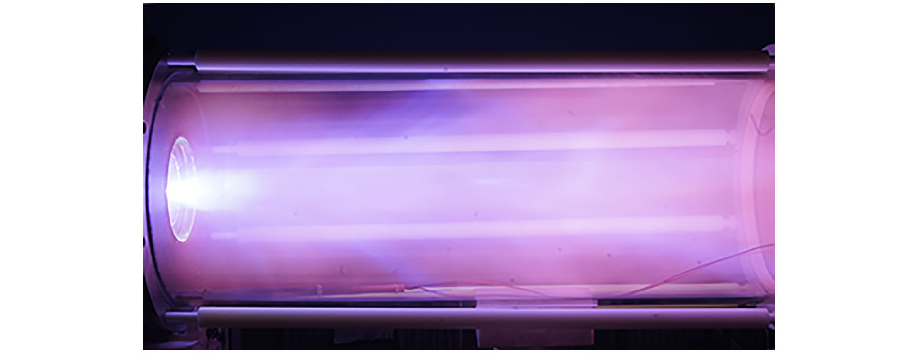 图 5 7 kV氩气负脉冲放电原图
 图 6 7 kV氩气(a)正、(b)负脉冲放电照片的RGB图像处理
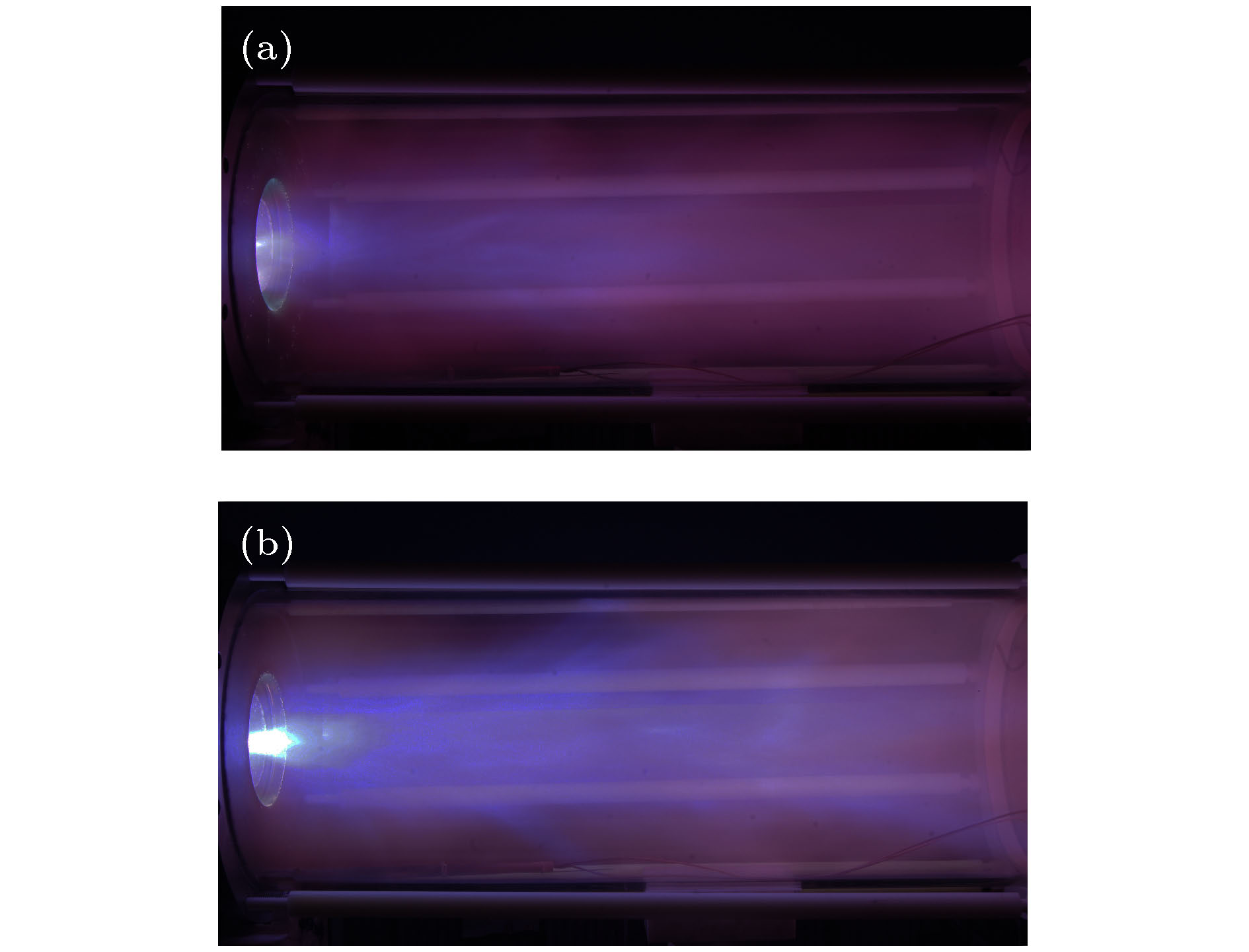 图 7 7 kV氩气(a)正、(b)负脉冲放电照片的图像亮度处理
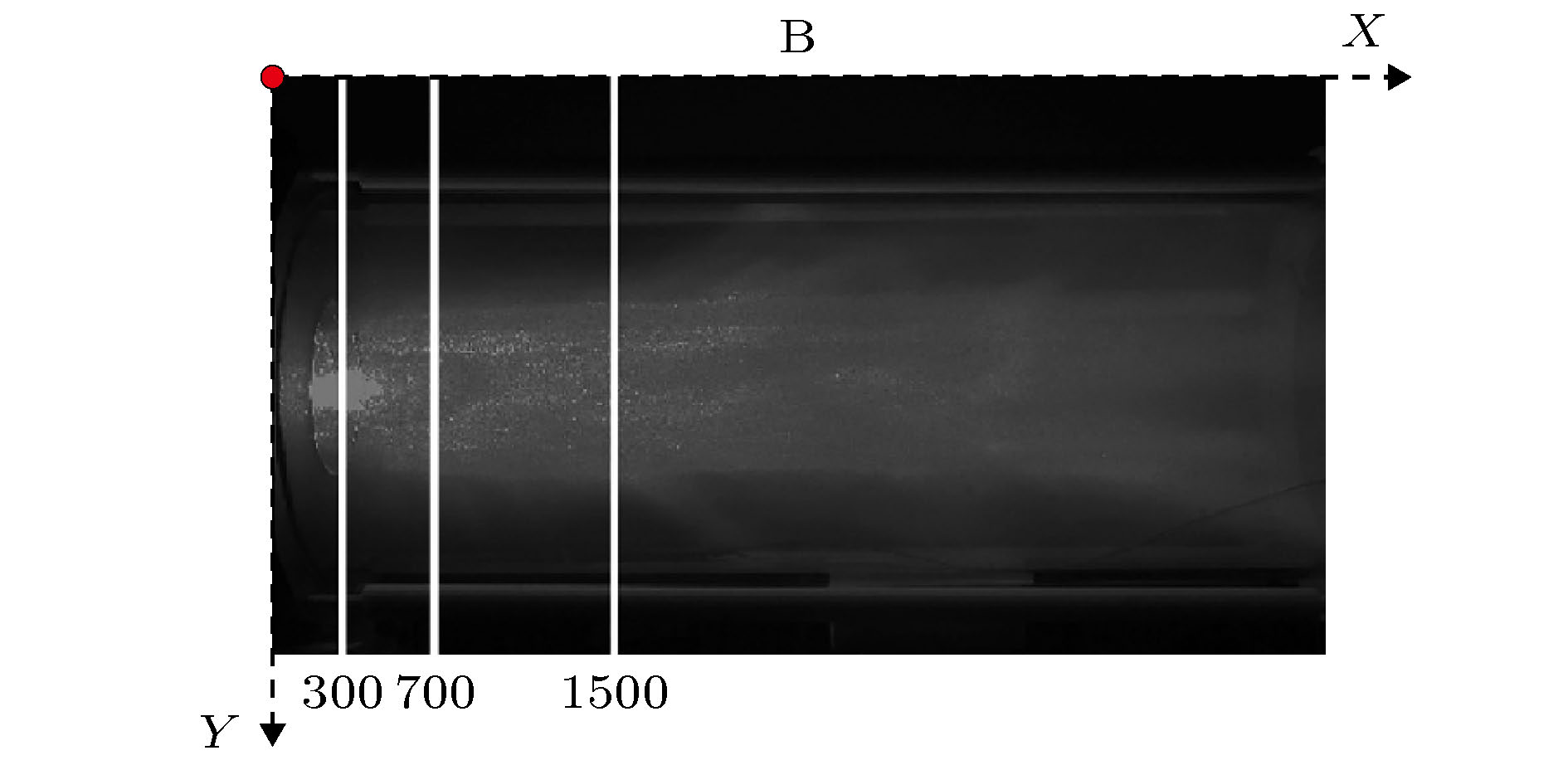 图 8 7 kV负脉冲放电条件下, 亮度处理蓝图X轴像素点300, 700, 1500位置示意图
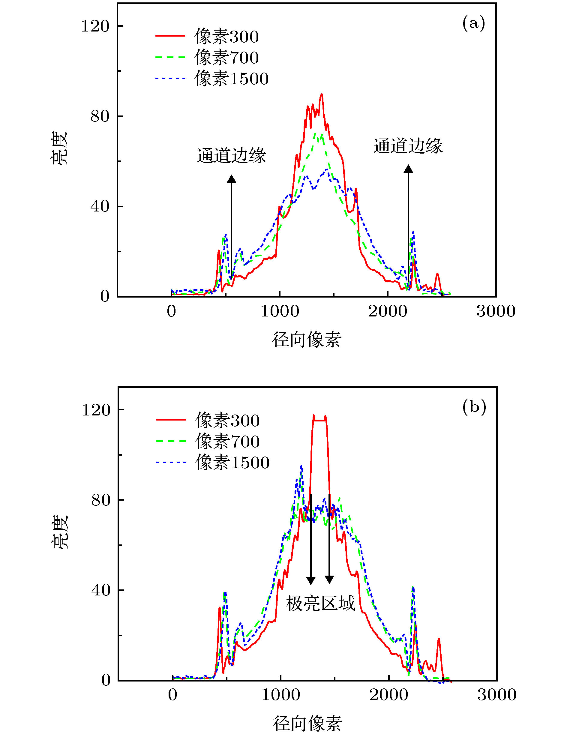 图 9 (a)正、(b)负脉冲放电蓝图X轴像素点300, 700, 1500 亮度径向分布
 图 10 7 kV, 10 Pa氩气正、负脉冲放电第一(a), (c)和第二(b), (d)团等离子体喷射高速相机拍照照片 (a), (b)正脉冲放电; (c), (d)负脉冲放电
 图 11 5.5 kV, 10 Pa氩气正(a)、负(b)脉冲放电电流、光信号和磁信号波形图

 图 12 同轴枪磁探针磁场测量
 图 13 10 Pa氩气正负脉冲等离子体速度对比
 图 14 10 Pa氩气正负脉冲等离子体密度对比