摘要: 分振幅型全Stokes同时偏振成像仪具有实时性好、空间分辨率高、精度高等优点, 有很高的应用价值. 分振幅型全Stokes同时偏振成像系统利用偏振分束器、1/2波片和1/4波片将入射光Stokes矢量调制在4幅图像中, 可解析入射光Stokes矢量. 1/2波片和1/4波片的相位延迟误差对Stokes矢量测量精度有着不可忽略的影响. 建立了包含上述两种误差的Stokes矢量测量误差方程, 分析了1/2波片和1/4波片相位延迟耦合误差对自然光、0°/45°线偏光、左旋圆偏光等典型基态入射光的Stokes矢量测量误差的影响, 推导了任意偏振态的Stokes矢量测量误差的表征方法. 在邦加球球面和球内选取不同偏振度的Stokes矢量作为入射光进行仿真. 结果表明, Stokes矢量测量误差和偏振度测量误差均随着入射光偏振度的增大而增大. 选取入射光偏振度为1时的偏振测量精度评估系统. 为满足2%的偏振测量精度, 1/2波片相位延迟误差应在±1.6°内, 1/4波片相位延迟误差应在±0.5°内. 这对提高系统的偏振测量精度具有重要意义, 为系统设计和研制提供了重要的理论指导.
关键词: 偏振成像 /
波片 /
相位延迟误差 /
Stokes矢量 English Abstract Phase delay error analysis of wave plate of division-of-amplitude full Stokes simultaneous polarization imaging system Yin Yu-Long 1,2,3 ,Sun Xiao-Bing 1,3 ,Song Mao-Xin 1,3 ,Chen Wei 1,2,3 ,Chen Fei-Nan 1,3 1.Anhui Institute of Optics and Fine Mechanics, Chinese Academy of Sciences, Hefei 230031, China Fund Project: Project supported by the National Key Research and Development Program of China (Grant No. 2016YFE0201400), the Common Key Technology Project for Satellite Application of China (Grant No. 30-Y20A010-9007-17/18), the National High Resolution Major Special Project of China (Grant No. GFZX04011805), and the Key Project of Hefei Research Institute of Chinese Academy of Sciences (Grant No. Y73H9P1801).Received Date: 18 August 2018Accepted Date: 20 October 2018Available Online: 01 January 2019Published Online: 20 January 2019Abstract: The division-of-amplitude full Stokes simultaneous polarization imaging system has prominent merits, such as real time, high spatial resolution, high precision, etc. The development of the division-of-amplitude full Stokes simultaneous polarization imaging system has a high application value. The division-of-amplitude full Stokes simultaneous polarization imaging system uses polarization beam splitters, a half wave plate (HWP) and a quarter wave plate (QWP) to modulate the incident Stokes vector into four intensity images. Using the four intensity images, the incident Stokes vector can be analyzed. In the system, the phase delay errors of the HWP and the QWP have a direct influence on the measurement accuracy of the incident Stokes vector. A Stokes vector measurement error equation containing the phase delay errors of the HWP and the QWP is established. When there are the phase delay errors of the HWP and the QWP in the system, the Stokes vector measurement errors of the unpolarized light, 0° liner polarized light, 90° liner polarized light, 45° liner polarized light, 135° liner polarized light, right circularly polarized light and left circularly polarized light are analyzed. A method of solving the Stokes vector measurement error of incident light with any polarization state is given. When the Stokes vectors with different degrees of polarization (DOPs) are used as the incident light, the simulation results show that both the Stokes vector measurement error and the DOP measurement error increase with the DOP of incident light increasing. Therefore, we select the polarization measurement accuracy to evaluate the system when the DOP of incident light equals 1. To ensure that the polarization measurement accuracy of the system is within 2%, the phase delay error of the HWP should be within ±1.6° and the phase delay error of the QWP should be within ±0.5°. The analysis results of the phase delay errors of the HWP and the QWP are of great significance for improving the polarization measurement accuracy of the division-of-amplitude full Stokes simultaneous polarization imaging system, and also provide important theoretical guidance in designing and developing the system.Keywords: polarization imaging /wave plate /phase delay error /Stokes vector 全文HTML --> --> --> 1.引 言 偏振是光的一种本质属性, 偏振信息不仅包含强度信息还包含偏振度、偏振角和椭圆度角等信息. 光与大气或目标相互作用时会改变光的偏振特性, 光的偏振特性的变化可以表征大气或目标的物理属性, 因此偏振探测广泛用于仿生导航、水下目标探测、天文探测、大气遥感、空间目标3D重建和生物医学等领域[1 ?6 ] . 为了实现目标偏振信息的探测, 需要研制高精度的偏振成像系统, 偏振成像系统可分为两类: 分时偏振成像系统和同时偏振成像系统. 分时偏振成像系统中普遍存在转动部件或分时调制器, 导致分时偏振成像系统无法偏振探测快速变化的目标. 为实现动态目标的偏振探测, 同时偏振成像系统的研制已成为研究热点. 1982年, Azzam[7 ] 最先提出一种基于振幅分割的同时偏振成像系统, 该系统利用镀膜分光器和Wollaston棱镜将入射光分为4束光, 由4个探测器实现了对入射光Stokes参数线偏振分量的同时测量. 2008年, Pezzaniti等[8 ] 成功研制了分振幅全Stokes同时偏振成像系统, 利用偏振分束器(polarization beam splitter, PBS)、1/2波片(half wave plate, HWP)和1/4波片(quarter wave plate, QWP)将入射光分为4束光, 由4个探测器实现对入射光全Stokes参数的同时测量. 2003年, Oka和Kaneko[9 ] 首次提出一种基于双折射楔形棱镜的通道调制型偏振成像仪, 随后国内外****对基于双折射楔形棱镜的通道调制型偏振成像仪进行了改进[10 ?12 ] , 提高了基于双折射楔形棱镜的通道调制型偏振成像仪的偏振探测性能. 2016年, 权乃承等[13 ] 提出一种基于孔径分割与视场分割的通道型成像光谱偏振技术, 并进行仿真分析验证了该方案的可行性. 2018年, 冯斌等[14 ] 研制了分焦平面同时偏振成像仪, 并给出了性能评估模型. 为了提高偏振测量精度, 国内外研究人员针对不同调制原理的同时偏振成像系统进行了系统参数误差分析等方面的工作[15 ?19 ] .2.分振幅型全Stokes同时偏振成像系统原理及误差建模 22.1.偏振成像系统工作原理 2.1.偏振成像系统工作原理 分振幅型全Stokes同时偏振成像系统原理如图1 所示, 入射光通过光学镜头后, 被部分偏振分束器(partial polarization beam splitter, PPBS)分成两路, 一路是从PPBS透射的光束, 被HWP调制后由PBS1分离为P偏振光和S偏振光, 从PBS1透射的P偏振光由CCD1接收, 反射的S偏振光由CCD2接收; 另一路是从PPBS反射的光束, 被QWP调制后由PBS2分离为P偏振光和S偏振光, 从PBS2透射的P偏振光由CCD3接收, 反射的S偏振光由CCD4接收.图 1 分振幅型全Stokes同时偏振成像系统原理图Figure1. Scheme of the division-of-amplitude full Stokes simultaneous polarization imaging system.20 ]研究了光学镜头的起偏效应. 以通常使用的玻璃进行分析, 当入射角很小(小于5°)时, 角度每相差1°, 造成的偏振度测量偏差为0.01%—0.03%. 本文研究的偏振成像系统是小视场成像系统, 入射主光束的入射方向与光学镜头法线的夹角很小, 所以不考虑光学镜头的起偏效应. 分振幅型全Stokes同时偏振成像系统4个通道的Mueller矩阵${{{M}}_{{\rm{path}}1}} $ ?$ {{{M}}_{{\rm{path}}4}}$ 为![]()
1 )—(3 )式中, ${T_{\rm{p}}}$ 和${T_{\rm{s}}}$ 分别为PPBS的p光透射系数和s光透射系数, ${{P}}\left( {{T_{\rm{p}}},{T_{\rm{s}}}} \right)$ 和${{P}}(1-{T_{\rm{p}}},$ $1-{T_{\rm{s}}})$ 分别为PPBS透射和反射时的Mueller矩阵; ${{P}}\left( {1,0} \right)$ 为PBS1和PBS2透射时的Mueller矩阵, ${{P}}\left( {0,1} \right)$ 为PBS1和PBS2反射时的Mueller矩阵; ${{Ret}}\left( {\theta ,\varphi } \right)$ 为波片(相位延迟量$\varphi $ )快轴与x 轴正向夹角为$\theta $ 时的Mueller矩阵.${{{S}}^\dagger }_{{\rm{in}}} = {[{{S}}_0^\dagger ,{{S}}_1^\dagger ,{{S}}_2^\dagger ,{{S}}_3^\dagger ]^{\rm{T}}}$ , 系统的测量矩阵为M ${{I}} = {[{{{I}}_{{\rm{path1}}}},{{{I}}_{{\rm{path2}}}},{{{I}}_{{\rm{path}}3}},{{{I}}_{{\rm{path4}}}}]^{\rm{T}}}$ 为M ${{I}}$ , 则可获得入射光Stokes矢量:2.2.波片相位延迟误差建模 -->2.2.波片相位延迟误差建模 PPBS的分束比为T p /T s , HWP和QWP相位延迟误差分别为$\sigma $ 和$\delta $ 时, 分振幅型全Stokes同时偏振成像系统4个通道的Mueller矩阵$ {{M}}_{{\rm{path}}1}^\dagger$ ?$ {{M}}_{{\rm{path}}4}^\dagger $ 和系统测量矩阵${{{M}}^\dagger }$ 分别如(6 )式和(7 )式所示:![]()
![]()
${{{M}}^{}}^\dagger $ , 则实际的入射光Stokes矢量${{{S}}_{{\rm{in}}}}$ 为5 )式可得计算的入射光Stokes矢量${{{S}}^\dagger }_{{\rm{in}}}$ , 则Stokes矢量的测量误差${{{e}}_{{S}}}$ 为9 )式中, ${e_{{{S}}i}}$ 表示Stokes矢量${{{S}}_i}$ 分量的测量误差(其中i = 0, 1, 2, 3), E R M [21 ] , 因此, 本文在接下来的波片相位延迟误差分析中, 将入射光Stokes矢量进行归一化处理.3.波片相位延迟误差仿真与分析 本文将采用基于典型基态入射光和基于邦加球采样的两种方法对系统中波片相位延迟误差进行仿真和分析. 基于典型基态入射光的方法通过研究典型基态入射光的Stokes矢量测量误差的变化规律便可分析出任意偏振态的入射光Stokes矢量测量误差的变化规律. 邦加球采样的方法可用于更加全面、完备地评估波片相位延迟误差对系统偏振测量精度的影响.3.1.基于典型基态入射光的波片相位延迟误差仿真及分析 3.1.基于典型基态入射光的波片相位延迟误差仿真及分析 任意偏振态的入射光Stokes矢量都可分解成7种典型基态入射光(自然光、0°/90°/45°/135°线偏振光、右旋和左旋圆偏振光) Stokes矢量的线性组合. 通过分析7种典型基态入射光的Stokes矢量测量误差, 便可解析任意偏振态的入射光Stokes矢量测量误差.${{{S}}_{{\rm{in}}}}$ 分解成自然光、0°/90°/45°/135°线偏振光、右旋和左旋圆偏振光Stokes矢量的线性组合表示为![]()
10 )式中, ${l_{2i - 1}} \!-\! {l_{2i}} = {{{{{S}}_i}} / {{{{S}}_0}}}$ 且${l_{2i - 1}} \cdot {l_{2i}} \;{\rm{ = 0}}\left( {i = 1,}\right.$ $\left. {2,3} \right)$ .9 )式可分别求出自然光、0°/90°/45°/135°线偏振光、右旋和左旋圆偏振光Stokes矢量的测量误差${{e}}_{{S}}^{(0)}$ ?$ {{e}}_{{S}}^{(6)}$ , 结合(10 )式可得任意偏振态的入射光Stokes矢量测量误差${{ e}_{{S}}}$ :![]()
表1 为分振幅型全Stokes同时偏振成像系统的设计参数, 以其为仿真参数, 则入射光分别为自然光、0°/90°/45°/135°线偏振光、右旋和左旋圆偏振光时, HWP和QWP相位延迟误差对入射光Stokes参数测量误差的影响如图2 所示. 其中 x 轴和y 轴分别为HWP相位延迟误差$\sigma $ 和QWP相位延迟误差$\delta $ (单位: (°)), z 轴为入射光Stokes参数测量误差.参数名称 参数值 1/2波片相位延迟量 180° 1/4波片相位延迟量 90° 1/2波片快轴方位角 ?22.5° 1/4波片快轴方位角 45° 部分偏振分束器分束比 T p /T s = 0.8/0.2
表1 分振幅型全Stokes同时偏振成像系统设计参数Table1. Parameters of division-of-amplitude full Stokes simultaneous polarization imaging system.图 2 不同入射光情况下的Stokes参数测量误差 (a) 自然光; (b) 0° 线偏光; (c) 90° 线偏光; (d) 45° 线偏光; (e) 135° 线偏光; (f) 右旋圆偏光; (g) 左旋圆偏光Figure2. Errors of Stokes parameters of different incident light: (a) Unpolarized light; (b) 0° liner polarized light; (c) 90° liner polarized light; (d) 45° liner polarized light; (e) 135° liner polarized light; (f) right circularly polarized light; (g) left circularly polarized light.图2 可知, 系统中同时存在HWP相位延迟误差$\sigma $ 和QWP相位延迟误差$\delta $ 时, 7种典型基态入射光${{S}_0}$ 分量和${{S}_1}$ 分量的测量误差均为0, ${{S}_2}$ 分量的测量误差仅受$\sigma $ 的影响, ${{S}_3}$ 分量的测量误差仅受$\delta $ 的影响.11 )式便可解析出任意偏振态的入射光Stokes矢量测量误差. 由图2 和(11 )式分析可知, 系统中同时存在HWP相位延迟误差$\sigma $ 和QWP相位延迟误差$\delta $ 时, 任意偏振态的入射光的${{S}_0}$ 分量和${{S}_1}$ 分量的测量误差均为0, 任意偏振态的入射光${{S}_2}$ 分量的测量误差仅受$\sigma $ 的影响, 任意偏振态的入射光${{S}_3}$ 分量的测量误差仅受$\delta $ 影响.3.2.基于邦加球采样的波片相位延迟误差仿真与分析 -->3.2.基于邦加球采样的波片相位延迟误差仿真与分析 由(9 )式可知, Stokes矢量测量误差随着入射光Stokes矢量的变化而变化, 为了更加完备地评估波片相位延迟误差对分振幅型全Stokes同时偏振成像系统的Stokes矢量测量精度的影响, 需要分析不同偏振态的Stokes矢量作为入射光时波片相位延迟误差对系统的Stokes矢量测量精度的影响.![]()
${{{S}}_n}$ 为邦加球球面上或球内的第n 个入射光采样点的归一化Stokes矢量, P 为偏振度, ${\chi _n}$ 和${\psi _n}$ 分别为第n 个入射光采样点${{{S}}_n}$ 的椭圆度角和偏振角, ${N_\chi }$ 表示从邦加球的南极到北极围绕球体采样的圆周个数, ${N_\psi }$ 表示每个采样圆周上的采样点数.12 )式中的P = 1, ${N_\chi }$ = 20, ${N_\psi }$ = 50, 则图3 为邦加球球面上1000个不同偏振态的Stokes矢量的三维分布和Stokes参数的数值分布.图 3 邦加球球面上选取1000个不同偏振态的Stokes矢量的 (a) 三维分布和(b) Stokes参数的数值分布Figure3. (a) 3D distribution and (b) stokes parameters values of 1000 Stokes vectors different degrees of polarization selected on the Poincaré sphere.表1 中的系统设计参数作为仿真参数, 以图3 中的1000个Stokes矢量作为入射光采样点, 则图4(a) 和图4(b) 分别为仅存在1°的HWP相位延迟误差时和仅存在1°的QWP相位延迟误差时1000个入射光采样点的Stokes参数${{{S}}_0}$ ?${{{S}}_3}$ 测量误差. 图4 中横坐标为入射光采样点从邦加球南极到北极的采样序数, 纵坐标为Stokes参数测量误差.图 4 1000个邦加球球面上的入射光采样点的Stokes参数测量误差 (a) 仅存在1°的 HWP相位延迟误差; (b) 仅存在1°的QWP相位延迟误差Figure4. The measurement errors of Stokes parameters of 1000 incident light sampling points selected on the Poincaré sphere is simulated: (a) There is only 1° phase delay error of HWP; (b) there is only 1° phase delay error of QWP in the system.图4(a) 可知, HWP相位延迟误差$\sigma $ 仅影响入射光${{{S}}_2}$ 分量的测量精度, 从邦加球的南极到赤道的采样过程中(即采样序数n 从1到500的过程中), ${{{S}}_2}$ 分量测量误差的绝对值逐渐变小; 从邦加球的赤道到北极的采样过程中(即采样序数n 从500到1000的过程中), ${{{S}}_2}$ 分量测量误差的绝对值逐渐变大. 由此可知, 入射光的椭圆度角的绝对值越小, 则${{{S}}_2}$ 分量测量误差的绝对值越小.图4(b) 可知, QWP相位延迟误差$\delta $ 仅影响入射光${{{S}}_3}$ 分量的测量精度, 从邦加球的南极到赤道的采样过程中(即采样序数n 从1到500的过程中), ${{{S}}_3}$ 分量测量误差的振幅逐渐变大; 从邦加球的赤道到北极的采样过程中(即采样序数n 从500到1000的过程中), ${{{S}}_3}$ 分量测量误差的振幅逐渐变小. 由此可知, 入射光的椭圆度角的绝对值越小, ${{{S}}_3}$ 分量测量误差的振幅越大; 入射光的椭圆度角恒定时, ${{{S}}_3}$ 分量的测量误差随入射光的偏振角变化而变化(在邦加球赤道处, 即入射光为线偏振光时, ${{{S}}_3}$ 分量的测量误差受入射光偏振角的影响最大).$\sigma $ 和$\delta $ 时, 入射光采样点(采样总数为${N_\chi } \cdot {N_\psi }$ )的偏振度均为P 时, 在${N_\chi } \cdot {N_\psi }$ 个入射光采样点中${{S}}_i$ 分量测量误差绝对值的最大值$\max \_{{{e}}_{{{S}}i}}\left( {\sigma ,\delta ,P} \right)$ (其中 i = 0, 1, 2, 3)为${e_{Si}}\left( {\sigma ,\delta ,P,n} \right)$ 表示HWP相位延迟误差为$\sigma $ 、QWP相位延迟误差为$\delta $ 且入射光采样点(采样总数为${N_\chi } \cdot {N_\psi }$ )的偏振度均为P 时第n 个入射光采样点的${{{S}}_i}$ 分量的测量误差. 与(13 )式对应的偏振测量精度${\rm{acc}}\_{{S}}\left( {\sigma ,\delta ,P} \right)$ 定义为图4 可知, 仅存在1° 的HWP相位延迟误差且入射光采样点均为完全偏振光时, 偏振测量精度${\rm{acc}}\_{{S}} \left( {\sigma ={1^ \circ },\delta =0,P = 1} \right)$ 为1.23%; 仅存在1° 的QWP相位延迟误差且入射光采样点均为完全偏振光时, 偏振测量精度${\rm{acc}}\_{{S}} \, (\sigma =0,\delta ={1^ \circ }, $ $P = 1) $ 为3.48%.表1 中的系统设计参数作为仿真参数, 分别令(12 )式中的偏振度$P$ 为1.0, 0.8, 0.5, 0.2和0.1, 不同偏振度对应的采样总数均为1000 (即(12 )式中恒有${N_\chi } $ = 20, ${N_\psi } $ = 50), 则当入射光采样点分别为邦加球球面上的完全偏振光($P$ = 1)和邦加球球内的部分偏振光($P$ 为0.8, 0.5, 0.2和0.1)时, HWP相位延迟误差$\sigma $ 或QWP相位延迟误差$\delta $ 对偏振测量精度${\rm{acc}}\_{{S}}\left( {\sigma ,\delta ,P} \right)$ 影响的仿真结果如图5 所示.图 5 不同偏振度的采样点作为入射光时对偏振测量精度的影响 (a) 仅HWP相位延迟误差; (b) 仅QWP相位延迟误差; (c) HWP和QWP相位延迟耦合误差Figure5. When the sampling points with different degrees of polarization are used as incident light, the effect of measurement accuracy: (a) The phase delay error of the HWP; (b) the phase delay error of the QWP; (c) the phase delay errors of the HWP and the QWP on polarization.图5(a) 中, 横坐标为HWP相位延迟误差$\sigma $ (单位为 (°)), 纵坐标为偏振测量精度${\rm{acc}}\_{{S}} ( \sigma ,\delta =$ $ 0,P )$ , 当偏振度P 恒定时, ${\rm{acc}}\_{{S}}\left ( {\sigma ,\delta = 0,P} \right)$ 的值随${\rm{|}}\sigma {\rm{|}}$ 增大而增大; 当$\sigma $ 恒定时, ${\rm{acc}}\_{{S}}\left( {\sigma ,\delta = 0,P} \right)$ 的值随偏振度P 增大而增大.图5(b) 中, 横坐标为QWP相位延迟误差$\delta $ (单位为 (°)), 纵坐标为偏振测量精度${\rm{acc}}\_{{S}}( \sigma = $ $0,\delta ,P)$ , 当偏振度P 恒定时, ${\rm{acc}}\_{{S}}\left( {\sigma = 0,\delta ,P} \right)$ 的值随$\left| \delta \right|$ 增大而增大; 当$\delta $ 恒定时, ${\rm{acc}}\_{{S}}( \sigma = $ $0,\delta ,P)$ 的值随偏振度P 增大而增大.图5(c) 为HWP和QWP相位延迟耦合误差对偏振测量精度${\rm{acc}}\_{{S}}\left( {\sigma ,\delta ,P} \right)$ 的影响, $\sigma $ 和$\delta $ 恒定时, ${\rm{acc}}\_{{S}}\left( {\sigma,\delta ,P} \right)$ 的值随偏振度P 增大而增大.图5 可知, HWP相位延迟误差$\sigma $ 或QWP相位延迟误差$\delta $ 恒定时, 入射光采样点的偏振度P = 1时对应的偏振测量精度${\rm{acc}}\_{{S}}\left( {\sigma ,\delta ,P = 1} \right)$ 为最大值, 因此, 采用${\rm{acc}}\_{{S}}\left( {\sigma ,\delta ,P = 1} \right)$ 来评估分振幅型全Stokes同时偏振成像系统的偏振测量精度. 系统中同时存在HWP和QWP相位延迟误差时, 系统的偏振测量精度${\rm{acc}}\_{{{S}}^{\left( {\sigma ,\delta } \right)}}$ 定义为3.3.波片相位延迟误差对偏振度测量精度的影响 -->3.3.波片相位延迟误差对偏振度测量精度的影响 偏振度的测量精度是评价分振幅型全Stokes同时偏振成像系统性能的重要指标, 入射光的Stokes矢量${{ S}_{{\rm{in}}}}{\rm{ = [}}{S_0},{S_1},{S_2},{S_3}{]^{\rm{T}}}$ 时, 偏振度$P = $ $ {{\sqrt {{S_1}^2 + {S_2}^2 + {S_3}^2} } / {{S_0}}}$ . 系统中同时存在HWP相位延迟误差$\sigma $ 和QWP相位延迟误差$\delta $ 时, 入射光的偏振度为P 时的偏振度测量误差$\Delta {P^{(\sigma ,\delta ,P)}}$ 为图2 和(11 )式分析可知, 系统中同时存在HWP和QWP相位延迟误差时, 任意偏振态的入射光${S_0}$ 分量的测量误差${e_{S0}}$ 和${S_1}$ 分量的测量误差${e_{S1}}$ 均为0. 因此(16 )式简化为表1 中的系统设计参数作为仿真参数, 以图3 中的1000个邦加球球面上(偏振度P 均为1)的Stokes矢量作为入射光采样点, 则图6(a) 和图6(b) 分别为仅存在1° 的HWP相位延迟误差时和仅存在1° 的QWP相位延迟误差时1000个邦加球球面上的入射光采样点的偏振度测量误差.图 6 1000个邦加球球面上的入射光采样点的偏振度测量误差 (a) 仅存在1°的HWP相位延迟误差; (b) 仅存在1°的QWP相位延迟误差Figure6. The measurement errors of DOP of 1000 incident light sampling points selected on the Poincaré sphere is simulated: (a) There is only 1° phase delay error of HWP; (b) there is only 1° phase delay error of QWP in the system.图6(a) 可知, 系统中仅存在HWP相位延迟误差$\sigma $ 时, 入射光从邦加球的南极到赤道的采样过程中(或者入射光从邦加球的赤道到北极的采样过程中), 偏振度测量误差$\Delta {P^{(\sigma ={1^ \circ },\delta =0,P = 1)}}$ 的振幅先增大后减小, 由此可知, 入射光为椭圆偏振光时, $\Delta {P^{(\sigma ={1^ \circ },\delta =0,P = 1)}}$ 随入射光偏振角的变化而变化(入射光的椭圆度角为 ±45° 时, $\Delta {P^{(\sigma ={1^ \circ },\delta =0,P = 1)}}$ 受入射光偏振角的影响最大). 由图6(b) 可知, 系统中仅存在QWP相位延迟误差$\delta $ 时, 入射光从邦加球的南极到赤道的采样过程中(或者入射光从邦加球的赤道到北极的采样过程中), 偏振度测量误差$\Delta {P^{(\sigma = 0,\delta ={1^ \circ },P = 1)}}$ 的振幅先增大后减小, 入射光为椭圆偏振光时, $\Delta {P^{(\sigma = 0,\delta ={1^ \circ },P = 1)}}$ 随入射光偏振角的变化而变化.$\sigma $ 和QWP相位延迟误差$\delta $ 时, 令(12 )式中的${N_\chi }$ = 20, ${N_\psi }$ = 50, 对于偏振度均为P 的1000个入射光采样点, 选择偏振度测量误差绝对值的最大值作为入射光偏振度为P 时的偏振度测量精度 ${\rm{acc}}\_P (\sigma ,\delta ,P)$ . 由图6 可知, 系统中仅存在1°的HWP相位延迟误差时, 入射光偏振度为1时的偏振度测量精度${\rm{acc}}\_P (\sigma ={1^ \circ },\delta =0,P=1)$ 为0.61%; 系统中仅存在1°的QWP相位延迟误差时, 入射光偏振度为1时的偏振度测量精度${\rm{acc}}\_P (\sigma {\rm{ = }}0, \delta {\rm{ = }}{1^ \circ }, P{\rm{ = }}1)$ 为2.08%.表1 中的系统设计参数作为仿真参数, 分别令(12 )式中偏振度$P$ 为1, 0.8, 0.5, 0.2和0.1, 不同偏振度对应的入射光采样总数均为1000 (即(12 )式中恒有${N_\chi }$ = 20, ${N_\psi }$ = 50), HWP相位延迟误差$\sigma \in \left( { - {2^ \circ },{2^ \circ }} \right)$ 且QWP相位延迟误差$\delta \in \left( { - {2^ \circ },{2^ \circ }} \right)$ 时, 则入射光的偏振度$P$ 分别为1, 0.8, 0.5, 0.2和0.1时的偏振度测量精度${\rm{acc}}\_P (\sigma ,\delta ,P)$ 的仿真结果如图7 所示. 由图7 可知, $\sigma $ 和$\delta $ 恒定时, 入射光的偏振度P 越大, 偏振度测量精度${\rm{acc}}\_P (\sigma ,\delta ,P)$ 的值越大, 因此选择入射光的偏振度P = 1时对应的偏振度测量精度${\rm{acc}}\_P (\sigma ,\delta ,P = 1)$ 来评估系统的偏振度测量精度.图 7 入射光的偏振度$P$ 分别为1.0, 0.8, 0.5, 0.2和0.1时, 偏振度测量精度${\rm{acc}}\_P (\sigma ,\delta ,P)$ 随HWP相位延迟误差$\sigma $ 和QWP相位延迟误差$\delta $ 的变化关系Figure7. Variation relation of measure accuracy ${\rm{acc}}\_P (\sigma ,\delta ,P)$ of DOP with the phase delay error of HWP and the phase delay error of QWP under the condition of $P$ = 1.0, 0.8, 0.5, 0.2 and 0.1.表1 中的系统设计参数作为仿真参数, 以图3 中1000个偏振度P 均为1的Stokes矢量作为入射光采样点, 则表2 和表3 分别为系统的偏振度测量精度${\rm{acc}}\_P(\sigma ,\delta ,P{\rm{ = }}1)$ 和系统偏振测量精度${\rm{acc}}\_{{{S}}^{\left( {\sigma ,\delta } \right)}}$ 随HWP相位延迟误差$\sigma $ 和QWP相位延迟误差$\delta $ 的变化关系.$\sigma $ $\delta$ ?1.0° ?0.9° ?0.6° ?0.5° 0° 0.5° 0.6° 0.9° 1.0° ?3.2° 3.22% 3.07% 2.65% 2.53% 2.03% 2.54% 2.68% 3.11% 3.26% ?3.1° 3.17% 3.02% 2.59% 2.47% 1.97% 2.48% 2.62% 3.05% 3.20% ?1.7° 2.50% 2.32% 1.82% 1.66% 1.06% 1.67% 1.83% 2.33% 2.50% ?1.6° 2.46% 2.28% 1.77% 1.61% 1.00% 1.62% 1.78% 2.28% 2.46% ?0.5° 2.13% 1.92% 1.31% 1.12% 0.31% 1.12% 1.31% 1.92% 2.13% 0° 2.09% 1.88% 1.25% 1.04% 0 1.04% 1.25% 1.88% 2.09% 0.5° 2.13% 1.92% 1.32% 1.12% 0.31% 1.12% 1.32% 1.92% 2.13% 1.6° 2.45% 2.27% 1.77% 1.62% 1.00% 1.61% 1.77% 2.27% 2.45% 1.7° 2.49% 2.31% 1.82% 1.67% 1.06% 1.66% 1.82% 2.31% 2.49% 3.1° 3.20% 3.05% 2.64% 2.50% 1.95% 2.46% 2.59% 3.02% 3.17% 3.2° 3.25% 3.11% 2.70% 2.57% 2.02% 2.52% 2.65% 3.07% 3.22%
表2 系统偏振度测量精度${\rm{acc}}\_P(\sigma ,\delta ,P {\rm{ = }} 1)$ 随HWP相位延迟误差$\sigma $ 和QWP相位延迟误差$\delta $ 的变化关系Table2. Variation relation of measure accuracy ${\rm{acc}}\_P(\sigma ,\delta ,P {\rm{ = }} 1)$ of DOP with the phase delay error $\sigma $ of HWP and the phase delay error $\delta $ of QWP.$\sigma$ $\delta $ ?1.0° ?0.9° ?0.6° ?0.5° 0° 0.5° 0.6° 0.9° 1.0° ?3.2° 4.01% 4.01% 4.01% 4.01% 4.01% 4.01% 4.01% 4.01% 4.01% ?3.1° 3.88% 3.88% 3.88% 3.88% 3.88% 3.88% 3.88% 3.88% 3.88% ?1.7° 3.48% 3.14% 2.11% 2.11% 2.11% 2.11% 2.11% 3.14% 3.48% ?1.6° 3.48% 3.14% 2.09% 1.99% 1.99% 1.99% 2.09% 3.14% 3.48% ?0.5° 3.48% 3.14% 2.09% 1.74% 0.62% 1.74% 2.09% 3.14% 3.48% 0° 3.48% 3.14% 2.09% 1.74% 0 1.74% 2.09% 3.14% 3.48% 0.5° 3.48% 3.14% 2.09% 1.74% 0.62% 1.74% 2.09% 3.14% 3.48% 1.6° 3.48% 3.14% 2.09% 1.99% 1.99% 1.99% 2.09% 3.14% 3.48% 1.7° 3.48% 3.14% 2.11% 2.11% 2.11% 2.11% 2.11% 3.14% 3.48% 3.1° 3.88% 3.88% 3.88% 3.88% 3.88% 3.88% 3.88% 3.88% 3.88% 3.2° 4.01% 4.01% 4.01% 4.01% 4.01% 4.01% 4.01% 4.01% 4.01%
表3 系统偏振测量精度${\rm{acc}}\_{{{S}}^{\left( {\sigma ,\delta } \right)}}$ 随HWP相位延迟误差$\sigma $ 和QWP相位延迟误差$\delta $ 的变化关系Table3. Variation relation of system polarization measurement accuracy ${\rm{acc}}\_{{{S}}^{\left( {\sigma ,\delta } \right)}}$ with the phase delay error $\sigma $ of HWP and the phase delay error $\delta $ of QWP.表2 和表3 可知, 系统中同时存在HWP相位延迟误差$\sigma $ 和QWP相位延迟误差$\delta $ 时, 恒有${\rm{acc}}\_{{S}}^{\left( {\sigma ,\delta } \right)} \succ {\rm{acc}}\_$ $ P (\sigma ,\delta ,P=1)$ . 为保证系统偏振测量精度${\rm{acc}}\_{{{S}}^{\left( {\sigma ,\delta } \right)}}$ 和系统的偏振度测量精度${\rm{acc}}\_P (\sigma ,\delta ,P{\rm{ = }}1)$ 均在2%以内, 则HWP相位延迟误差应在 ±1.6°内, QWP相位延迟误差应在 ±0.5°内.4.实验结果与分析 为了验证本文对分振幅型全Stokes偏振成像系统波片相位延迟误差分析结论的正确性, 搭建了如图8 所示的实验光路, 实验光路由偏振态发生器(polarization state generator, PSG)、四分束偏振分析器(four-paths polarization analyzer)和陷阱探测器(trap detector)组成. 其中, PSG由He-Ne激光器、激光功率控制器(laser power controller, LPC)、退偏器、安装在电动转台上的偏振片和图 8 波片相位延迟误差分析实验光路Figure8. Experimental optical path of wave plate phase delay error analysis.表4 和表5 所列. 实验中四分束偏振分析器4个通道的Mueller矩阵${ M}_{\tau ,{\rm{path}}1}^{}$ —${ M}_{\tau ,{\rm{path}}4}^{}$ 为参数名称 参数值 He-Ne激光器输出波长 632.99 nm He-Ne激光器光强稳定性 ± 0.1% 电动转台旋转精度 0.005° 偏振片消光系数 ≥ 10000∶1 零级QWP相位延迟量 89.87°@632.99 nm
表4 实验光路中PSG的主要参数Table4. Parameters of PSG in the experimental optical path.参数名称 参数值 PPBS分束比${{T_{\rm p}^{({\rm PPBS})}} / {T_{\rm s}^{({\rm PPBS})}}}$ 0.788/0.191 零级HWP相位延迟量 179.74°@632.99 nm 零级QWP相位延迟量 89.87°@632.99 nm 零级HWP快轴方位角 ?22.5° 零级QWP快轴方位角 45° PBS1分束比${{T_{\rm{p}}^{({\rm{PBS1}})}} / {T_{\rm{s}}^{({\rm{PBS1}})}}}$ 0.981/0.0007 PBS2分束比${{T_{\rm{p}}^{({\rm{PBS2}})}} / {T_{\rm{s}}^{({\rm{PBS2}})}}}$ 0.988/0.0008
表5 实验光路中四分束偏振分析器的主要参数Table5. Parameters of the four-paths polarization analyzer in the experimental optical path.表5 中PPBS, PBS1和PBS2的分束比代入(18 )式, 并令$\sigma $ = ?0.26°和$\delta $ = ?0.13°, 得到四分束偏振分析器的实际测量矩阵${{{M}}_1}^\dagger $ . 将表5 中PPBS, PBS1和PBS2的分束比代入(18 )式, 并令$\sigma $ = 0和$\delta $ = 0, 得到估算的测量矩阵${{{M}}_0}$ .z 轴的正方向, 垂直于实验平台向上为y 轴的正方向(坐标系满足右手法则). 利用PSG产生偏振度为1的标准偏振光, PSG起始状态为: QWP快轴与x 轴的夹角为0°, 偏振片的透光轴与x 轴的夹角为?45°. 将PSG中的QWP以步长$\omega $ = 6°进行逆时针旋转, PSG中的偏振片以步长$\varpi\; {\rm{ = }}\;\omega {\rm{ \;+\; 0}}{\rm{.}}{{\rm{3}}^ \circ }\;{\rm{ = }}\;{6.3^ \circ }$ 进行逆时针旋转, 同时旋转n 次共产生300个不同偏振态的完全偏振光${\mathop {{S}} }_{{\rm{in}}}^{{\rm{PSG}}}(n)$ (n = 1, 2, ···, 300), 相当于(12 )式中的P = 1, ${N_\chi }$ = 10, ${N_\psi }$ = 30, 均匀分布在邦加球球面上的300个采样点.${{S}}_{{\rm{in}}}^{{\rm{PSG}}}(n)$ 对应的光强度矢量${{ I}_1}(n){\rm{ = }}$ ${[{I_{1,{\rm{path1}}}}(n),{I_{1,{\rm{path}}2}}(n),{I_{1,{\rm{path}}3}}(n),{I_{1,{\rm{path4}}}}(n)]^{\rm{T}}}$ (n = 1, 2, ···, 300), 与${{S}}_{{\rm{in}}}^{{\rm{PSG}}}(n)$ 对应的真实值为${{S}}_{{\rm{in}}}^{'{\rm{(1,real)}}}(n) =$ $ {\left( {{{{M}}_1}^\dagger } \right)^{ - 1}} \cdot {{{I}}_1}(n)$ (n = 1, 2, ···, 300), 归一化后的真实值为${{S}}_{{\rm{in}}}^{(1,{\rm{real}})}(n)$ (n = 1, 2, ···, 300).9 )式可得入射光Stokes矢量的估算值为${{S}}_{{\rm{in}}}^{(1,{\rm{estimated}})}(n){\rm{ = }}{\left( {{{{M}}_0}} \right)^{{\rm{ - }}1}} \cdot {{{M}}_1}^\dagger \cdot {{S}}_{{\rm{in}}}^{{\rm{(1,real)}}}(n)$ (n = 1, 2, ···, 300), 入射光Stokes矢量的测量误差为${{e}}_{{S}}^{(1)}(n) =$ $ {{S}}_{{\rm{in}}}^{{\rm{(1,estimated)}}}(n) - {{S}}_{{\rm{in}}}^{{\rm{(1,real)}}}(n)$ (n = 1, 2, ···, 300). 偏振度$P = {{\sqrt {{{{S}}_1}^2 + {{{S}}_2}^2 + {{{S}}_3}^2} } / {{{{S}}_0}}}$ , 由${{S}}_{{\rm{in}}}^{(1,{\rm{real}})}(n)$ 和${{S}}_{{\rm{in}}}^{{\rm{(1,estimated)}}}(n)$ 可分别获得入射光的真实偏振度$P^{(1,{\rm{real}})}(n)$ 和估算偏振度$P^{(1,{\rm{estimated}})}(n)$ , 偏振度的测量误差为$P^{(1,{\rm{error}})}(n) = P^{{\rm{(1,estimated)}}}(n)-$ $ P^{{\rm{(1,real)}}}(n)$ (n = 1, 2, ···, 300).$\sigma $ = ?0.26°和QWP相位延迟误差$\delta $ = ?0.13°同时存在时, 入射光Stokes矢量和偏振度的测量结果如图9 所示, 入射光从邦加球的南极到北极的采样过程中, ${{{S}}_0}$ 分量的测量误差和${{{S}}_1}$ 分量的测量误差为0 , ${{{S}}_2}$ 分量测量误差的绝对值先减小后增大, ${{{S}}_3}$ 分量测量误差的振幅先增大后减小, 与图4 仿真结果的变化规律一致. 入射光从邦加球的南极到赤道的采样过程中(或从邦加球的赤道到北极的采样过程中), 偏振度测量误差的振幅先增大后减小, 与图6 仿真结果的变化规律相符.图 9 实验中HWP相位延迟误差$\sigma$ = ?0.26°和QWP相位延迟误差$\delta $ = ?0.13°时的测量结果 入射光 (a) ${{{S}}_0}$ 分量; (b) ${{{S}}_1}$ 分量; (c) ${{{S}}_2}$ 分量; (d) ${{{S}}_3}$ 分量; (e) 偏振度Figure9. Measurement results: (a) ${{{S}}_0}$ component; (b) ${{{S}}_1}$ component; (c) ${{{S}}_2}$ component; (d) ${{{S}}_3}$ component; (e) DOP of the incident light under the condition of $\sigma $ = ?0.26° and $\delta$ = ?0.13°.图9 结果显示, 偏振测量精度${\rm{acc}}\_{{S}}(\sigma =$ $ - {{0.26}^ \circ },\delta = - 0.13^ \circ,P=1)$ 为0.44%, 偏振度测量精度${\rm{acc}}\_P(\sigma = -{0.26^ \circ },\delta = - 0.13^ \circ, P=1)$ 为0.33%, 与表2 和表3 的仿真结果相符合, 即HWP相位延迟误差在 ±1.6°内, 且QWP相位延迟误差在 ±0.5°内时, 偏振测量精度和偏振度测量精度均小于2%.5.结 论 本文针对分振幅型全Stokes同时偏振成像仪中HWP和QWP相位延迟误差对入射光Stokes矢量测量精度影响较大的问题, 建立了包含HWP和QWP相位延迟误差的Stokes矢量测量误差模型, 仿真了自然光、0°/90°/45°/135°线偏振光、右旋和左旋圆偏振光分别作为入射光时, HWP和QWP相位延迟耦合误差对Stokes矢量测量误差的影响, 给出了求解任意偏振态入射光的Stokes矢量测量误差的方法. 仿真结果表明, 同时存在HWP和QWP相位延迟误差时, 任意偏振态的入射光的${{{S}}_0}$ 分量和${{{S}}_1}$ 分量的测量误差均为0, 任意偏振态的入射光${{{S}}_2}$ 分量的测量误差仅受HWP相位延迟误差的影响, 任意偏振态入射光${{{S}}_3}$ 分量的测量误差仅受QWP相位延迟误差的影响. 为了更加完备地分析HWP和QWP相位延迟误差对系统偏振测量精度的影响, 本文提出分别在邦加球的球面和球内选取不同偏振度的Stokes矢量作为入射光, 在此基础上仿真了HWP和QWP相位延迟误差对偏振测量精度${\rm{acc}}\_{{S}}\left( {\sigma ,\delta ,P} \right)$ 和偏振度测量精度${\rm{acc}}\_P(\sigma ,\delta ,P)$ 的影响. 仿真结果表明, HWP和QWP相位延迟误差恒定时, 偏振测量精度${\rm{acc}}\_{{S}}\left( {\sigma ,\delta ,P} \right)$ 的值和偏振度测量精度${\rm{acc}}\_P(\sigma ,\delta ,P)$ 的值都随着偏振度P 的增大而增大, 因此, 选取入射光偏振度为1时对应的偏振测量精度${\rm{acc}}\_{{S}} $ $\left( {\sigma ,\delta ,P = 1} \right)$ 和偏振度测量精度${\rm{acc}}\_P(\sigma ,\delta ,$ $P=1)$ 来评估系统. 为保证系统偏振测量精度和偏振度测量精度均在2%内, HWP相位延迟误差应在 ±1.6°内, QWP相位延迟误差应在 ±0.5°内. 这对分振幅型全Stokes同时偏振成像系统的光学参数设计、波片相位延迟的加工精度要求和系统研制具有重要的意义. 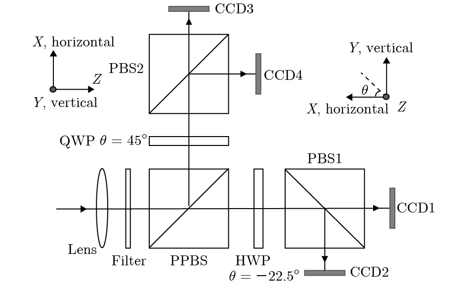 图 1 分振幅型全Stokes同时偏振成像系统原理图


 图 2 不同入射光情况下的Stokes参数测量误差 (a) 自然光; (b) 0° 线偏光; (c) 90° 线偏光; (d) 45° 线偏光; (e) 135° 线偏光; (f) 右旋圆偏光; (g) 左旋圆偏光


 图 3 邦加球球面上选取1000个不同偏振态的Stokes矢量的 (a) 三维分布和(b) Stokes参数的数值分布

 图 4 1000个邦加球球面上的入射光采样点的Stokes参数测量误差 (a) 仅存在1°的 HWP相位延迟误差; (b) 仅存在1°的QWP相位延迟误差


 图 5 不同偏振度的采样点作为入射光时对偏振测量精度的影响 (a) 仅HWP相位延迟误差; (b) 仅QWP相位延迟误差; (c) HWP和QWP相位延迟耦合误差


 图 6 1000个邦加球球面上的入射光采样点的偏振度测量误差 (a) 仅存在1°的HWP相位延迟误差; (b) 仅存在1°的QWP相位延迟误差


 图 7 入射光的偏振度


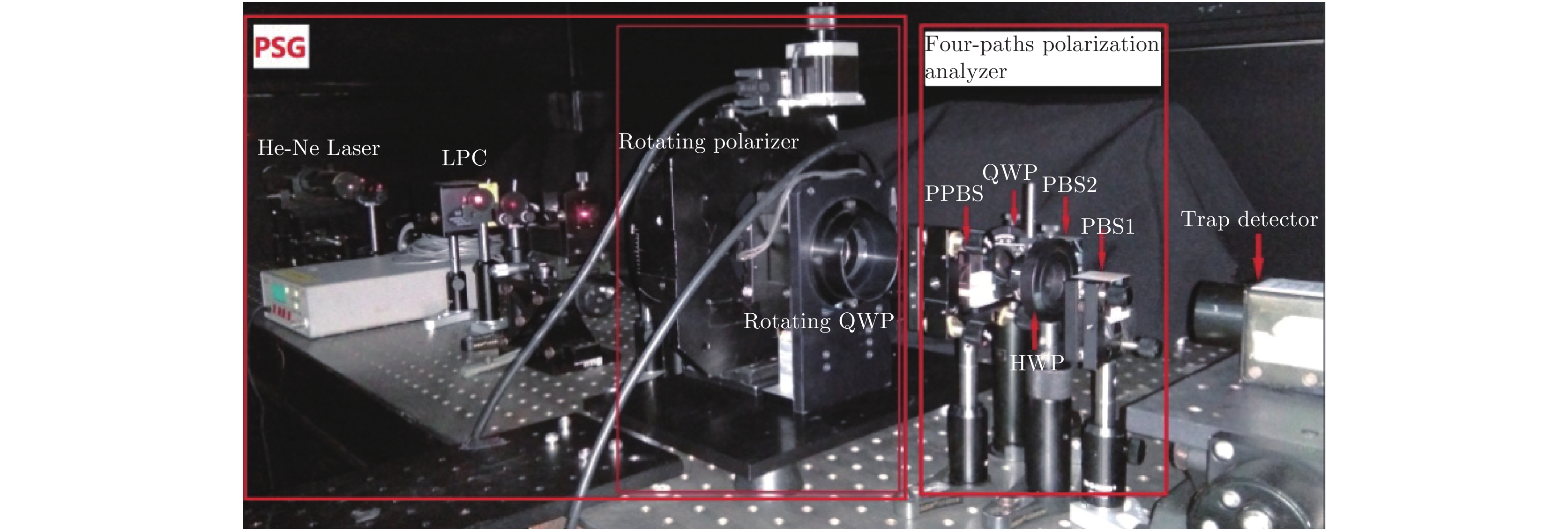 图 8 波片相位延迟误差分析实验光路


 图 9 实验中HWP相位延迟误差


