张静,王哲
(北京交通大学 土木建筑工程学院,北京100044)
摘要:
为研究混凝土材料在多轴循环荷载作用下的非线性特性,基于经典塑性力学理论和边界面模型理论,提出一个改进的边界面模型.模型中,屈服面为封闭、光滑曲面,在子午面内为梨形;边界面与屈服面的形状相似;选择应力的第一不变量和应变偏量作为屈服面函数中的自变量;相应的加卸载判据中的微分变量也是上述两种变量;根据屈服面和边界面形状的相似性,通过比例关系定义映射法则;对于处在屈服面上的任意一个当前应力点,根据此法则,都能够找到与之对应的处在边界面上的映射点,两个点对应的曲面法线方向相同;采用非相关流动法则描述塑性变形.对沿着偏平面上的压缩方向,对混凝土试块分别进行单调加载和循环加载时的试验结果,用本构模型进行模拟,模型计算结果与试验结果吻合.模型能够统一地描述应力-应变曲线的上升-下降段,能够描述剪胀现象.
关键词: 循环荷载 边界面模型 映射法则 剪胀 偏平面
DOI:10.11918/j.issn.0367-6234.201802050
分类号:O344.3;TU528.01
文献标识码:A
基金项目:国家自然科学基金(3,4)
A pear-shaped bounding surface constitutive model for concrete
ZHANG Jing,WANG Zhe
(School of Civil Engineering, Beijing Jiaotong University, Beijing 100044,China)
Abstract:
To investigate the nonlinear properties of concrete under multiaxial cyclic loading, an improved bounding surface model was presented for concrete within the framework of elastoplastic and bounding surface theory. The yield surface is closed and smooth, and in tensile and compressive meridan planes, the yield surface is a pear shape. The shape of bounding surface is similar to yield surface. The first stress invariant and the strain deviation were adoped as the independent variables in the yield function and as the differential variable in the loading and unloading criteria. Based on the similarity of the shape between yield and bounding surfaces, the mapping relations were determined by proportional relations. According to the mapping rules, there always was an image stress point on the bounding surface for a current stress point on the yield surface. The two points had the same normal direction for corresponding surfaces, and a nonassociated flow was adopted to describe the plastic deformation. For the experimental results of concrete specimens under monotonic and cyclic loading along the compression direction in the deviatoric plane, the proposed model was used to simulate the results numerically. The calculated results agree well with experimental data. The model can describe the pre-failure and post-failure stress-strain curve and describe the shear dilatancy of concrete.
Key words: cyclic loading bounding surface model mapping relations shear dilatancy deviatoric plane
张静, 王哲. 混凝土的一种梨形边界面本构模型[J]. 哈尔滨工业大学学报, 2018, 50(8): 142-149. DOI: 10.11918/j.issn.0367-6234.201802050.

ZHANG Jing, WANG Zhe. A pear-shaped bounding surface constitutive model for concrete[J]. Journal of Harbin Institute of Technology, 2018, 50(8): 142-149. DOI: 10.11918/j.issn.0367-6234.201802050.

基金项目 国家自然科学基金(51279003,51078024) 作者简介 张静(1986―),女,博士研究生;
王哲(1961―),男,研究员,博士生导师 通信作者 王哲, zhwang@bjtu.edu.cn 文章历史 收稿日期: 2018-02-14
Contents -->Abstract Full text Figures/Tables PDF
混凝土的一种梨形边界面本构模型
张静, 王哲


北京交通大学 土木建筑工程学院,北京 100044
收稿日期: 2018-02-14
基金项目: 国家自然科学基金(51279003,51078024)
作者简介: 张静(1986―),女,博士研究生;
王哲(1961―),男,研究员,博士生导师
通信作者: 王哲, zhwang@bjtu.edu.cn
摘要: 为研究混凝土材料在多轴循环荷载作用下的非线性特性,基于经典塑性力学理论和边界面模型理论,提出一个改进的边界面模型.模型中,屈服面为封闭、光滑曲面,在子午面内为梨形;边界面与屈服面的形状相似;选择应力的第一不变量和应变偏量作为屈服面函数中的自变量;相应的加卸载判据中的微分变量也是上述两种变量;根据屈服面和边界面形状的相似性,通过比例关系定义映射法则;对于处在屈服面上的任意一个当前应力点,根据此法则,都能够找到与之对应的处在边界面上的映射点,两个点对应的曲面法线方向相同;采用非相关流动法则描述塑性变形.对沿着偏平面上的压缩方向,对混凝土试块分别进行单调加载和循环加载时的试验结果,用本构模型进行模拟,模型计算结果与试验结果吻合.模型能够统一地描述应力-应变曲线的上升-下降段,能够描述剪胀现象.
关键词: 循环荷载 边界面模型 映射法则 剪胀 偏平面
A pear-shaped bounding surface constitutive model for concrete
ZHANG Jing, WANG Zhe


School of Civil Engineering, Beijing Jiaotong University, Beijing 100044, China
Abstract: To investigate the nonlinear properties of concrete under multiaxial cyclic loading, an improved bounding surface model was presented for concrete within the framework of elastoplastic and bounding surface theory. The yield surface is closed and smooth, and in tensile and compressive meridan planes, the yield surface is a pear shape. The shape of bounding surface is similar to yield surface. The first stress invariant and the strain deviation were adoped as the independent variables in the yield function and as the differential variable in the loading and unloading criteria. Based on the similarity of the shape between yield and bounding surfaces, the mapping relations were determined by proportional relations. According to the mapping rules, there always was an image stress point on the bounding surface for a current stress point on the yield surface. The two points had the same normal direction for corresponding surfaces, and a nonassociated flow was adopted to describe the plastic deformation. For the experimental results of concrete specimens under monotonic and cyclic loading along the compression direction in the deviatoric plane, the proposed model was used to simulate the results numerically. The calculated results agree well with experimental data. The model can describe the pre-failure and post-failure stress-strain curve and describe the shear dilatancy of concrete.
Key words: cyclic loading bounding surface model mapping relations shear dilatancy deviatoric plane
混凝土材料不仅应用于房屋建筑结构,还大量应用于重力坝、高拱坝、核电站预应力混凝土安全壳以及隧道衬砌等复杂结构.这些结构大都在动力和多向应力状态下工作,对其加-卸载响应的研究,对材料应力-应变关系的描述是更全面掌握此材料特性及进行定量分析的基础.混凝土材料具有的静水压力相关性、剪切压缩-膨胀现象、应变软化行为等特性导致其荷载响应复杂多样,建立合理的本构模型是进行混凝土结构非线性分析的基础.
本构模型的发展经历了增量理论[1],剪切应变和随动硬化理论[2-3],多面模型[4-5],边界面塑性[6-8].其中边界面模型以其形式简单、应用方便、可描述复杂的三轴循环加载等优点被许多学者用来描述混凝土在循环荷载下的性能.Dafalia等[6]和Krieg[9]首次提出边界面的概念,并将其应用于金属及土体.Fardis等[7]第一次用此模型来模拟混凝土的性能:模型不包含屈服面,方程为增量形式,仅可模拟塑性变形,不可模拟软化行为.Fardis等[8]提出增量形式的边界面模型,没有屈服面,可描述混凝土的弹性和塑性应变及软化现象;Yang等[10]提出增量形式的边界面模型,包含两个加载面,考虑等向损伤,可描述混凝土软化行为;Suaris等[11]提出全量形式的边界面模型,考虑了异向损伤,但不能模拟混凝土软化行为.屠永清[12]、王湛等[13]对边界面模型进行了一定研究, 并用边界面模型模拟混凝土在单轴单调、单轴循环荷载作用下的应力-应变曲线、应力-体积应变曲线.
一般的边界面模型中,塑性模量的确定不依赖于硬化函数和一致性条件,仅根据边界面和屈服面的位置关系确定,相比数学逻辑关系严密的经典塑性力学模型是一缺陷.屈服面的形式选取是研究混凝土弹塑性本构模型的一个重要方向.通常屈服面在子午面内是开口的,或者盖帽组合式.前者模型表明屈服应力可随静水压力无限增长,这与实验结果不符;后者模型或存在角点问题,不便进行数值计算,或曲线在连接点处连续,但公式较多.任放等[14]建议的蛋形屈服面能够很好弥补以上两类屈服面的缺点,此类模型参数相对较少,且其形式更适用于混凝土材料,但被应用于本构模型及数值化较少,仅有少量文献[15-16]涉及.
借鉴边界面模型优点,建立一个适用于循环加载作用下的混凝土本构模型.子午面上的屈服面采用了更符合实际且不通过原点的梨形面,将有效塑性偏应变作为硬化参数.通过引入剪胀参数,将塑性偏应变增量与剪切引起的塑性体积应变增量联系起来,进而推导增量形式的边界面弹塑性本构关系,实现数值模拟.结合课题组有关偏平面上循环加载的试验数据[17],对模型进行验证.结果表明该模型能够较合理模拟混凝土在偏平面上的应力-应变关系.
1 弹性和塑性应变分解本文模型中,假设材料是各向同性的,弹性和弹塑性响应都是率无关的.定义应力和应变以压缩为正,拉伸为负.
总应变增量dεij由弹性和塑性两部分组成
${\rm{d}}{\varepsilon _{ij}} = {\rm{d}}\varepsilon _{ij}^{\rm{e}} + {\rm{d}}\varepsilon _{ij}^{\rm{p}},$ (1)
式中dεije和dεijp分别表示弹性和塑性应变增量.
弹性部分由胡克定律表示为
${\rm{d}}\varepsilon _{ij}^{\rm{e}} = {\rm{d}}e_{ij}^{\rm{e}} + \frac{{{\rm{d}}\varepsilon _{\rm{v}}^{\rm{e}}}}{3}{\delta _{ij}} = \frac{{{\rm{d}}{s_{ij}}}}{{2G}} + \frac{{{\rm{d}}{\sigma _{kk}}}}{{9K}}{\delta _{ij}}.$ (2)
式中:deije为弹性偏应变增量;dεve为弹性体积应变增量;dsij为偏应力增量;dσij为应力增量;δij为Kronecker张量;G为弹性剪切模量;K为弹性体积模量.G和K可由杨氏模量E和泊松比υ求出.
塑性部分表示为
${\rm{d}}\varepsilon _{ij}^{\rm{p}} = {\rm{d}}e_{ij}^{\rm{p}} + \frac{{{\rm{d}}\varepsilon _{\rm{v}}^{\rm{p}}}}{3}{\delta _{ij}},$ (3)
式中deijp为塑性偏应变增量,dεvp为塑性体积应变增量.
2 塑性部分边界面塑性本构关系主要由屈服面方程、边界面方程、映射法则和内变量演化方程4个要素组成.
2.1 屈服面和边界面的形式对于岩土、混凝土类工程材料,边界面在子午面内的形状有以下几种:直线[19-20]、单个椭圆[21-22]、由封闭逐渐开口的非均匀硬化加载面[23-24]、椭圆-双曲线[18]、椭圆-抛物线[25]的多段曲线组合、水滴形状或蛋形[14-16, 26-27].
本文边界面模型包含一个由f=0决定的屈服面和一个由F=0决定的边界面.借鉴任放等[14]研究成果,提出以下梨形函数作为屈服面函数:
$f = {\left( {\frac{{{\sigma _{\rm{m}}} - c}}{a}} \right)^2} + {\left( {\frac{{1 - p}}{{1 + p\frac{{{\sigma _{\rm{m}}} - c}}{a}}}} \right)^2}{\left( {\frac{{\sqrt {{J_2}} }}{{bg\left( \theta \right)}}} \right)^2} - 1,$ (4)
而
$\begin{array}{l}{\sigma _{\rm{m}}} = \frac{1}{3}{\sigma _{kk}} = \frac{1}{3}{I_1},\\{J_2} = \frac{1}{2}\left[ {2G\left( {{e_{ij}} - e_{ij}^{\rm{p}}} \right) - {\alpha _{ij}}} \right]\left[ {2G\left( {{e_{ij}} - e_{ij}^{\rm{p}}} \right) - {\alpha _{ij}}} \right].\end{array}$
式中:σm为平均应力,I1为应力σij的第一不变量;eij和eijp分别为偏应变张量和塑性偏应变张量;J2为偏应力sij的第二不变量;αij为屈服面在π平面上的中心;g(θ)为屈服面在π平面上的形状函数,θ为罗德角;p为子午面内屈服面形状的修正系数,当-1<p<0时,为剑桥弹头形曲面,当0<p<1时,为梨形曲面,当p=0时,为椭圆,此时a、b及c分别表示椭圆的长短半轴及在σm轴上的中心.
a、b、c和αij为内变量,在加载过程中会发生变化,其变化规律用微分方程描述,这些方程称为演化方程.其中a和b控制屈服面的大小,c和αij控制屈服面的位置.假设在变化的过程中a与b始终保持固定比例,记b/a=t1.
通过改进摩尔-库伦破坏面函数,消除棱角影响,提出g(θ)的函数形式如下
$g\left( \theta \right) = \frac{1}{{\left( {1 + \kappa } \right) + {{\left( {1 - \kappa } \right)}^2}{{\sin }^2}3\theta - \left( {1 - \kappa } \right)\cos 3\theta }},$ (5)
其中κ为π平面上屈服面形状的修正系数.
边界面函数采用与屈服面函数相似的形式,取为
$F = {\left( {\frac{{{{\bar \sigma }_{\rm{m}}} - \bar c}}{{\bar a}}} \right)^2} + {\left( {\frac{{1 - p}}{{1 + p\frac{{{{\bar \sigma }_{\rm{m}}} - \bar c}}{{\bar a}}}}} \right)^2}{\left( {\frac{{\sqrt {{{\bar J}_2}} }}{{\bar bg\left( {\bar \theta } \right)}}} \right)^2} - 1,$ (6)
式中σm、J2、a、b、c和θ分别为边界面中对应的量,表达形式和含义均类似于以上屈服面中的定义.边界面在π平面上的中心用αij表示.
记
Figure 1
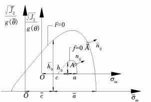 图 1 子午面内边界面和屈服面示意 Figure 1 Schematic illustration of bounding surface, yield surface in the meridian plane
 2.2 映射法则映射关系定义为:如图 1所示,A为屈服面上的当前应力点,A为边界面上一点,若两点有相同的单位法向向量,就认为A为A的映射点.
假设以下式子成立:
$\theta = \bar \theta ,$ (7)
$\frac{{{\sigma _{\rm{m}}} - c}}{a} = \frac{{{{\bar \sigma }_{\rm{m}}} - \bar c}}{{\bar a}},$ (8)
$\frac{{\sqrt {{J_2}} }}{b} = \frac{{\sqrt {{{\bar J}_2}} }}{{\bar b}}.$ (9)
若屈服面上应力点对应的θ、σm、J2及边界面上应力点对应的θ、σm、J2满足式(7)~(9),则两个点有相同的单位法向向量,即满足本文定义的映射关系.
定义距离d1和d2,其表达式分别如下:
${d_1} = {{\bar I}_1} - {I_1},$ (10)
${d_2} = \sqrt {\left( {{{\bar s}_{ij}} - {s_{ij}}} \right)\left( {{{\bar s}_{ij}} - {s_{ij}}} \right)} ,$ (11)
式中I1为边界面上映射应力σij的第一不变量.
为方便后续应用,引入与d2相关的量化距离:
$\delta = \frac{{{{\left( {{d_2}} \right)}_0} - {d_2}}}{{{{\left( {{d_2}} \right)}_0}}},$ (12)
式中(d2)0为当前应力点由弹性区域刚到达屈服面时对应的d2值.之后若持续加载,其保持不变;若卸载进入弹性区域,则下一次加载时重新计算(d2)0.
2.3 硬化准则屈服面和边界面的大小分别由内变量a、b和a、b确定,位置分别由内变量c、αij和c、αij确定.
2.3.1 屈服面的内变量演化方程假设在加载过程中,屈服面的大小和形状不发生变化,但位置能够变化.
构造屈服面内变量的演化方程分别为
${\rm{d}}a = 0,$ (13)
${\rm{d}}b = 0,$ (14)
${\rm{d}}c = {\rm{d}}\bar c + {\gamma _1}{d_1} \cdot {\rm{d}}\lambda + {\gamma _2}\left( {{\sigma _{\rm{m}}} - c} \right)\frac{{{\rm{d}}\left( {\bar a} \right) - {\rm{d}}\left( a \right)}}{a},$ (15)
$\begin{array}{l}{\rm{d}}{\alpha _{ij}} = {\rm{d}}{{\bar \alpha }_{ij}} + \frac{{{m_1}{{\left( {{d_2}} \right)}_0}\left( {{{\bar s}_{ij}} - {s_{ij}}} \right){\rm{d}}{e_{\rm{p}}}}}{{\left[ {1 + {m_2}{{\left( {{{\left( {{d_2}} \right)}_0}} \right)}^2}} \right]{{\left( {{d_2} + \mathit{\Delta} } \right)}^{0.5}}}} + \\\;\;\;\;\;\;\;\;\left[ {2G\left( {{e_{ij}} - e_{ij}^{\rm{p}}} \right) - {\alpha _{ij}}} \right]\frac{{{\rm{d}}\bar b - {\rm{d}}b}}{b}.\end{array}$ (16)
显然式(13)和(14)能够保证屈服面的大小不变.式(15)和(16)是通过分析试验数据和研究已有的演化方程得到的.式(15)中,dλ为非负比例因子;γ1和γ2为正值材料常数.式(16)中,Δ为一个较小正值,用来避免分母为零,本文取Δ=10-8;m1和m2为正值材料常数;dep=
2.3.2 边界面的内变量演化方程假设在加载过程中,边界面的大小发生变化,边界面的形状不变,边界面在静水压力轴方向的位置发生变化,但是边界面在偏平面内的位置不发生变化.在加载过程中,b和a都发生变化,但是由于边界面形状不变,二者的比值为定值.这里取b/a=b/a=t1.
假设a的变化一部分是由静水压力引起,另一部分由偏应变引起,取
${\rm{d}}\bar a = {\rm{d}}\left( {\bar \mu \cdot \bar r} \right),$ (17)
式中:μ为与静水压力相关的函数,r为与偏应变相关的函数.μ与r的演变公式分别为
${\rm{d}}\bar \mu = {l_1}\frac{{{\rm{d}}{I_1}}}{{\left| {{\rm{d}}{I_1}} \right|}}{\rm{d}}\lambda ,$ (17a)
${\rm{d}}\bar r = \frac{{{l_2}\chi }}{{\chi {e_{\rm{p}}} + 0.1}}{\rm{d}}{e_{\rm{p}}}.$ (17b)
式(17a)中,l1为正值材料常数.式(17b)中,l2为负值材料常数;χ=χ1eχ2I'1, χ1为正值材料常数,χ2为负值材料常数,I'1=I1/fc,fc为混凝土的单轴抗压强度;ep=∫dep为等效塑性偏应变.
边界面的其余内变量的演化方程为
${\rm{d}}\bar b = {t_1}{\rm{d}}\bar a,$ (18)
${\rm{d}}\bar c = \left( {1 + {t_2}\ln \left( {1 + 35\left| {{{I'}_1}} \right|} \right)} \right){\rm{d}}\bar \mu ,$ (19)
${\rm{d}}{{\bar \alpha }_{ij}} = 0,$ (20)
式中t1和t2为正值材料常数.
式(19)中,内变量c将沿着I1变化的方向移动.通过选取合适的参数,同时结合内变量a的演化,可以描述混凝土材料在经历三向等压荷载历史后,单轴抗压强度会有所降低的特性.当进行三向等压加载时,a增大,c沿着I1增大方向移动,边界面在高静水压力区一侧不断膨胀,而在另一侧收缩,这种变化形式比较类似于文献[27]提出的混凝土不均匀强(软)化.
2.4 塑性应变增量对于混凝土材料,静水压力仅引起体积变化,由静水压力所产生的塑性体积应变,通常考虑一个塑性体积模量即可近似计算.而剪应力的变化既会产生剪应变,又会引起体积应变的发生.
对于剪切引起的塑性变形,采用非相关流动法则.把剪切引起的塑性应变增量的方向nijp分解为两项
$n_{ij}^{\rm{p}} = n_{ij}^{\left( 1 \right)} + n_{ij}^{\left( 2 \right)}.$ (21)
其中
$n_{ij}^{\left( 1 \right)} = \frac{{\partial f}}{{\partial {\sigma _{ij}}}} - \frac{1}{3}\frac{{\partial f}}{{\partial {I_1}}}{\delta _{ij}},$ (21a)
$n_{ij}^{\left( 2 \right)} = \frac{{\omega \zeta }}{{{{\left( {100qe + 1} \right)}^{2.5}}}}{\delta _{ij}}.$ (21b)
在式(21a)中
$\frac{{\partial f}}{{\partial {\sigma _{ij}}}} = \frac{{\partial f}}{{\partial {I_1}}}\frac{{\partial {I_1}}}{{\partial {\sigma _{ij}}}} + \frac{{\partial f}}{{\partial {I_2}}}\frac{{\partial {I_2}}}{{\partial {\sigma _{ij}}}} + \frac{{\partial f}}{{\partial g\left( \theta \right)}}\frac{{\partial g\left( \theta \right)}}{{\partial {\sigma _{ij}}}}.$ (22)
在式(21b)中
$\begin{array}{l}\omega = \left( {{e_{11}} - {e_{22}}} \right)\left( {n_{11}^{\left( 1 \right)} - n_{22}^{\left( 1 \right)}} \right) + \\\;\;\;\;\;\;\left( {{e_{22}} - {e_{33}}} \right)\left( {n_{22}^{\left( 1 \right)} - n_{33}^{\left( 1 \right)}} \right) + \\\;\;\;\;\;\;\left( {{e_{33}} - {e_{11}}} \right)\left( {n_{33}^{\left( 1 \right)} - n_{11}^{\left( 1 \right)}} \right),\end{array}$
$qe = \sqrt {\frac{1}{2}\left[ {{{\left( {{e_{11}} - {e_{22}}} \right)}^2} + {{\left( {{e_{22}} - {e_{33}}} \right)}^2} + {{\left( {{e_{33}} - {e_{11}}} \right)}^2}} \right]} .$
式(21)中,第一项nij(1)描述的是剪切引起的塑性应变中的关联流动部分;第二项nij(2)为修正项,修正剪切引起的塑性应变与其关联流动部分的偏差.
式(21b)是通过分析体积应变εv与广义剪应变qe之间的关系曲线得到的.用ζ反映剪切应变对体积应变的影响,其表达式为
$\zeta = {\zeta _1} + {\zeta _2},$ (23)
其中
${\zeta _1} = {z_1}\left( {{k_1}{{I'}_1} + {k_2} - \delta } \right){{\rm{e}}^{ - {z_2}{{\left( {\delta - 0.9} \right)}^2}}},$
${\zeta _2} = {z_3}\left( {qe - q{e_{\max }}} \right){{\rm{e}}^{ - {z_4}{{\left( {qe - q{e_{\max }}} \right)}^2}}}.$
式中:ζ1反映剪切应变引起的体积压缩;ζ2反映剪切应变引起的体积膨胀;z1、z2、z3和z4均为正值材料常数;qemax为qe经历的最大值.
因此,剪切引起的塑性应变增量d(εijp)s可表示为
${\rm{d}}{\left( {\varepsilon _{ij}^{\rm{p}}} \right)_{\rm{s}}} = n_{ij}^{\rm{p}}{\rm{d}}\lambda = {\rm{d}}e_{ij}^{\rm{p}} + \frac{{{\delta _{ij}}}}{3}{\rm{d}}{\left( {\varepsilon _{\rm{v}}^{\rm{p}}} \right)_{\rm{s}}}.$ (24)
其中
${\rm{d}}e_{ij}^{\rm{p}} = n_{ij}^{\left( 1 \right)}{\rm{d}}\lambda ,$ (24a)
${\rm{d}}{\left( {\varepsilon _{\rm{v}}^{\rm{p}}} \right)_{\rm{s}}} = n_{kl}^{\left( 2 \right)}{\delta _{kl}}{\rm{d}}\lambda .$ (24b)
式中d(εvp)s表示剪切引起的塑性体积应变增量.
由静水压力引起的塑性体积应变增量可表示为
${\rm{d}}{\left( {\varepsilon _{\rm{v}}^{\rm{p}}} \right)_{\rm{h}}} = \frac{{{\rm{d}}{\sigma _{kk}}}}{{9{K^{\rm{p}}}}},$ (25)
式中:Kp为塑性体积模量.
则总塑性体积应变增量表示为
${\rm{d}}\varepsilon _{\rm{v}}^{\rm{p}} = {\rm{d}}{\left( {\varepsilon _{\rm{v}}^{\rm{p}}} \right)_{\rm{s}}} + {\rm{d}}{\left( {\varepsilon _{\rm{v}}^{\rm{p}}} \right)_{\rm{h}}}.$ (26)
2.5 一致性条件屈服面函数f的形式有3种:f=f1(σij, Z),f=f2(εij, Z),f=f3(I1, eij, Z).式中Z表示内变量的集合,本文中Z≡(eijp, αij, a, b, c).
在整个塑性加载过程中,一致性条件成立.根据3种形式的屈服函数,相应有3种形式的微分方程df=0.这里只对第3种进行详细讨论.
结合式(13)~(20)和式(24a),dλ可通过一致性条件得到.在整个塑性加载过程中,df3=0,进一步有
$\begin{array}{l}\frac{{\partial {f_3}}}{{\partial {I_1}}}{\rm{d}}{I_1} + \frac{{\partial {f_3}}}{{\partial {e_{ij}}}}{\rm{d}}{e_{ij}} + \frac{{\partial {f_3}}}{{\partial e_{ij}^{\rm{p}}}}{\rm{d}}e_{ij}^{\rm{p}} + \frac{{\partial {f_3}}}{{\partial {\alpha _{ij}}}}{\rm{d}}{\alpha _{ij}} + \\\frac{{\partial {f_3}}}{{\partial a}}{\rm{d}}a + \frac{{\partial {f_3}}}{{\partial b}}{\rm{d}}b + \frac{{\partial {f_3}}}{{\partial c}}{\rm{d}}c = 0.\end{array}$ (27)
由式(27)可求得dλ,然后带入式(24a)、(24b)求出deijp,d(εvp)s,进而得到增量应力-应变关系.
2.6 加卸载准则为对塑性变形对应的加卸载进行判断,需引入与屈服函数f相关的加载函数L.
每一种形式的屈服面函数对应有一组加卸载判别公式,共有3组:
当f1(σij, Z)=0, L1=
当f2(εij, Z)=0, L2=
当f3(I1, eij, Z)=0, L3=
仅对f3 对应的加卸载准则进行讨论:
1) 当f3<0时,弹性状态,内变量不变;
2) 当f3=0时,塑性状态,材料状态点在屈服面上,应用加卸载判别公式,有a)若L3>0,则为应力球量和应变偏量联合加载,使用式(13)~(20)来计算内变量的增量;b)若L3≤0,则为卸载或中性变载,内变量增量为零.f1、f2对应的加卸载准则的判别方法与f3的相似.
3 模型计算与试验数据比较 3.1 材料参数的选取模型验证采用的是课题组在大连理工大学进行的混凝土三轴试验的部分数据[17].经过对数据处理和试算,所有模拟采用的同一组参数见表 1.
表 1
数值 2.90×10⁴ 1.54×10⁵ 0.50 986.00 2.30×10⁴ 0.17 0.60 0.06 -1.80 0.80 0.71 3.83 4.10 0.05 0.10 27.00 0.06 0.78 150.00 -2.56
表 1 数值试验的模型参数 Table 1 Model constants for numerical experiment
除以上参数,模型中的参变量a、a、b、b、c和c需要赋予初值,分别为a0=2 MPa,a0=38 MPa,b0=t1a0,b0=t1a0,c0=1.2 MPa和c0=21.6 MPa.另Kp=2 620 MPa,fc=35 MPa.
3.2 计算流程图计算程序采用fortran语言编写.对静水压力加载部分,以平均应力驱动开始计算;对于偏应力加载部分,以偏应变驱动开始计算.前者计算过程较简单,仅给出偏应变驱动的计算过程流程图(见图 2).
Figure 2
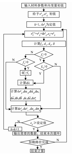 图 2 本构模型对应的程序框图 Figure 2 Calculation flowchart for the constitutive model
 3.3 模型验证利用上述计算程序,结合课题组有关偏平面加载的部分试验数据与本文的计算结果进行比较验证.
试验是在若干个偏平面上沿压缩路径分别进行了单调加载和循环加载.加载分为两个阶段,先施加应力球量,然后再施加应力偏量,按照应力增量dσy=dσz=-dσx/2的约束关系改变荷载.本文采用的试验数据中,σm选取了3档:σm=30、45、60 MPa;单轴压缩时θ=0°,按照每档σm与θ的组合可分为3组加载路径.
模型计算结果与试验结果的比较见图 3~6.由于篇幅限制且试块的离散性较低[17],对于单调路径,选取每组路径的2块试验数据参与比较分析;对于循环路径,选取每组路径的1块试验数据参与比较分析.
Figure 3
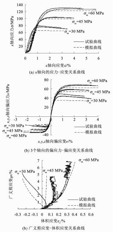 图 3 偏平面上单调压缩加载的响应曲线 Figure 3 Model simulation for monotonic compression test in the π plane
 Figure 4
 图 4 偏平面上循环压缩加载的响应曲线:σm=30 MPa Figure 4 Model simulation for cyclic compression test in the π plane:σm=30 MPa
 Figure 5
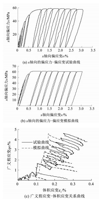 图 5 偏平面上循环压缩加载的响应曲线:σm=45 MPa Figure 5 Model simulation for cyclic compression test in the π plane:σm=45 MPa
 Figure 6
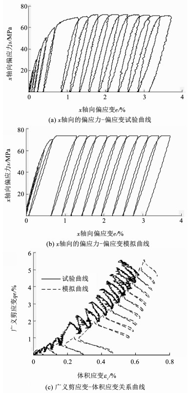 图 6 偏平面上循环压缩加载的响应曲线:σm=60 MPa Figure 6 Model simulation for cyclic compression test in the π plane:σm=60 MPa
 从计算曲线来看,1)单调加载下,模拟得到的应力-应变曲线在两个阶段的表现都与试验曲线比较吻合(见图 3(a)~(b));2)多轴加载下,无论单调或者循环应力状态,由本文模型计算得到的偏应力-偏应变曲线,其变化规律及趋势与试验结果基本一致(见图 3(b)、4(a)~(b)、5(a)~(b)和6(a)~(b)),循环加载曲线的滞回环宽度较小,应是某些方程形式的确定不合适;3)体积应变的变化与试验曲线在低围压时偏差较多,高围压时更吻合,是由于选取的参数ζ的表达式不合适,但是基本趋势是正确的(见图 3(c)、4(c)、5(c)和6(c)).总体上模型预测结果和试验结果是比较接近的.
4 结论提出一种可描述材料循环加载的边界面塑性本构模型,其中的屈服面和边界面是封闭且不过原点的梨形曲面.引入的映射法则,可以确保当前应力点和映射应力点的法线方向始终相同.模型的加卸载判据中的微分变量是应力的第一不变量和应变偏量,根据它们的增量来判断加卸载,模型能够模拟材料的应变-软化行为.在考虑剪切引起塑性变形时,采用了非相关流动法则.
把模型的计算结果与试验结果进行了比较,模型能够模拟混凝土在多轴加载后的多种特性.
参考文献
[1] COONM D, EVANS R J. Incremental constitutive laws and their associated failure criteria with application to plain concrete[J]. International Journal of Solids and Structures, 1972, 8(9): 1169. DOI:10.1016/0020-7683(72)90030-3
[2] PASTOR M, ZIENKIEWICZ O C, CHAN A H C. Generalized plasticity and the modeling of soil behaviour[J]. International Journal for Numerical and Analytical Methods in Geomechanics, 1990, 14(3): 151. DOI:10.1002/nag.1610140302
[3] LADE P V, KIM M K. Single hardening constitutive model for frictional materials, Ⅱ. Yield criterion and plastic work contours.[J]. Computers and Geotechnics, 1988, 6(1): 13. DOI:10.1016/0266-352X(88)90053-5
[4] MRóZ Z. On the description of anisotropic work-hardening[J]. Journal of the Mechanics and Physics of Solids, 1967, 15(3): 163. DOI:10.1016/0022-5096(67)90030-0
[5] MRóZ Z, NORRIS V A, ZIENKIEWICZ O C. Application of an anisotropic hardening model in the analysis of elasto-plastic deformation of soils[J]. Géotechnique, 1979, 29(1): 1. DOI:10.1680/geot.1979.29.1.1
[6] DAFALIAS Y F, POPOV E P. A model of nonlinearly hardening materials for complex loadings[J]. Acta Mechanica, 1974, 21(3): 173. DOI:10.1007/BF01181053
[7] FARDIS M N, ALIBE B, TASSOULAS J L. Monotonic and cyclic constitutive law for concrete[J]. Journal of Engineering Mechanics, 1983, 109(2): 516. DOI:10.1061/(ASCE)0733-9399(1983)109:2(516)
[8] FARDIS M N, CHEN E S. A cyclic multiaxial model for concrete[J]. Computational Mechanics, 1986, 1(4): 301. DOI:10.1007/BF00273706
[9] KRIEG R D. A practical two surface plasticity theory[J]. Journal of Applied Mechanics, 1975, 42(3): 641. DOI:10.1115/1.3423656
[10] YANG B L, DAFALIAS Y F, HERRMANN L R. A bounding surface plasticity model for concrete[J]. Journal of Engineering Mechanics, 1985, 111(3): 359. DOI:10.1061/(ASCE)0733-9399(1985)111:3(359)
[11] SUARIS W, OUYANG C, FERNANDO V M. Damage model for cyclic loading of concrete[J]. Journal of Engineering Mechanics, 1990, 116(5): 1020. DOI:10.1061/(ASCE)0733-9399(1990)116:5(1020)
[12] 屠永清, 钟善桐. 混凝土本构关系边界面模型的改进[J]. 哈尔滨建筑大学学报, 1995, 28(3): 29.
TU Yongqing, ZHONG Shantong. Modification of the bounding surface model for constitutive relationship of concrete[J]. Journal of Harbin University of Civil Engineering and Architecture, 1995, 28(3): 29.
[13] 王湛, 甄永辉. 混凝土本构关系边界面模型[J]. 工程力学, 1999, 16(3): 120.
WANG Zhan, ZHEN Yonghui. A bounding surface model for concrete constitutive relationship[J]. Engineering Mechanics, 1999, 16(3): 120.
[14] 任放, 盛谦, 常燕庭. 岩土类工程材料的蛋形屈服函数[J]. 岩土工程学报, 1993, 15(4): 33.
REN Fang, SHENG Qian, CHANG Yanting. Egg shaped yield function for geotechnical engineering materials[J]. Chinese Journal of Geotechnical Engineering, 1993, 15(4): 33.
[15] 章东. 混凝土的蛋形屈服面塑性本构模型[D]. 北京: 北京交通大学, 2009.
ZHANG Dong. Concrete plastic constitutive model with egg yield surface[D]. Beijing: Beijing Jiaotong University, 2009. http://cdmd.cnki.com.cn/Article/CDMD-10004-2010040832.htm
[16] 徐日庆, 杨林德, 龚晓南. 土的边界面应力应变本构关系[J]. 同济大学学报, 1997, 25(1): 29.
XU Riqing, YANG Linde, GONG Xiaonan. The stress - strain constitutive relationship of bounding surface for soils[J]. Journal of Tongji University, 1997, 25(1): 29.
[17] 王哲, 宋玉普, 尚仁杰. 应力偏量加载条件下混凝土力学行为试验研究[J]. 水利学报, 2001, 42(6): 648.
WANG Zhe, SONG Yupu, SHANG Renjie. The experimental study about the behaviour of concrete under the loading of deviatoric stress[J]. Journal of Hydraulic Engineering, 2001, 42(6): 648. DOI:10.13243/j.cnki.slxb.2011.06.006
[18] DAFALIAS Y F, HERRMANN L R. A bounding surface soil plasticity model[C]//International Symposium on Soils under Cyclic and Transient Loading. Swansea, 1980: 335.
[19] GAJO A, WOOD M. Severn-Trent sand: A kinematic hardening constitutive model for sands: The q - p formulation[J]. Géotechnique, 1999, 49(5): 595. DOI:10.1680/geot.1999.49.5.595
[20] MENETREY P, WILLAM K J. Triaxial failure criterion for concrete and its generalization[J]. Structural Journal, 1995, 92(3): 311.
[21] 李涛, MEISSNERH. 循环荷载作用下饱和黏性土的弹塑性双面模型[J]. 土木工程学报, 2006, 39(1): 92.
LI Tao, MEISSNER H. Elastoplastic two-surface model for clays under undrained cyclic loading[J]. China Civil Engineering Journal, 2006, 39(1): 92-97. DOI:10.15951/j.tmgcxb.2006.01.019
[22] 李剑, 陈善雄, 姜领发. 循环荷载作用下黏土改进边界面模型[J]. 岩土力学, 2015, 36(2): 387.
LI Jian, CHEN Shanxiong, JIANG Lingfa. An improved bounding surface model for clay under cyclic loading[J]. Rock and Soil Mechanics, 2015, 36(2): 387. DOI:10.16285/j.rsm.2015.02.013
[23] HAN D J, CHEN W F. A nonuniform hardening plasticity model for concrete materials[J]. Mechanics of Materials, 1985, 4(3/4): 283. DOI:10.1016/0167-6636(85)90025-0
[24] IMRAN I, PANTAZOPOULOU S J. Plasticity model for concrete under triaxial compression[J]. Journal of Engineering Mechanics, 2001, 127(3): 281. DOI:10.1061/(ASCE)0733-9399(2001)127:3(281)
[25] 殷宗泽. 一个土体的双屈服面应力-应变模型[J]. 岩土工程学报, 1988, 10(4): 64.
YIN Zongze. A stress-strain model of soil with double yield surface[J]. Chinese Journal of Geotechnical Engineering, 1988, 10(4): 64.
[26] KHALILI N, HABTE M A, VALLIAPPAN S. A bounding surface plasticity model for cyclic loading of granular soils[J]. Numerical Methods in Engineering, 2005, 63(14): 1939. DOI:10.1002/nme.1351
[27] LIU X L, WEN B, XU J F. A new elastoplastic kinematic hardening and softening model for concrete[J]. Advances in Structural Engineering, 2003, 6(2): 111. DOI:10.1260/136943303769013200
