Zhaohui Hong,Run Liu
(State Key Laboratory of Hydraulic Engineering Simulation and Safety, Tianjin University, Tianjin 300072, China)
Abstract:
Due to high temperature and pressure, unburied or shallow buried submarine pipelines experience lateral global buckling. Excessive bending caused by uncontrolled deformation may threaten the safety of the pipeline system. Thus, the integer of a post-buckling pipeline section should be assessed under design temperature and pressure differences. This study focuses on the post-buckling pipeline safety assessment. First, a series of model tests based on sand obtained from Bohai Gulf were proposed, and soil resistance to pipelines with different embedment are measured. A dynamic soil resistance model with varying pipeline embedment and lateral displacement was established. The influence of embedment on peak soil resistance and residual soil resistance was analyzed. Second, the critical buckling forces of pipelines with different imperfections were analyzed. A “critical force range” was proposed to evaluate whether the pipeline exhibits lateral global buckling or not. Third, the limit state of a post-buckling pipeline in an engineering case was assessed. The assessment was proposed based on both load control condition and displacement control condition. Further comparisons show that pipelines reach their limit state according to load control condition far more quickly than according to displacement control condition.
Key words: submarine pipelines lateral buckling pipe-soil interaction numerical research post-buckling pipeline assessment
DOI:10.11916/j.issn.1005-9113.18028
Clc Number:TE54
Fund:
Zhaohui Hong, Run Liu. Submarine Pipeline Lateral Global Buckling and Buckling Failure Critical State Discussion[J]. Journal of Harbin Institute of Technology (New Series), 2018, 25(5): 33-43. DOI: 10.11916/j.issn.1005-9113.18028.

Fund Sponsored by the National Basic Key Research Program of China (Grant No.2014CB046802), the National Natural Science Foundation of China (Grant No.51679162) Corresponding author Run Liu, Winner of the National Science Fund for Excellent Young Scholars and the Program for New Century Excellent Talents in University of Ministry of Education. E-mail: liurun@tju.edu.cn Article history Received: 2018-03-21
Contents Abstract Full text Figures/Tables PDF
Submarine Pipeline Lateral Global Buckling and Buckling Failure Critical State Discussion
Zhaohui Hong, Run Liu


State Key Laboratory of Hydraulic Engineering Simulation and Safety, Tianjin University, Tianjin 300072, China
Received: 2018-03-21
Fund: Sponsored by the National Basic Key Research Program of China (Grant No.2014CB046802), the National Natural Science Foundation of China (Grant No.51679162)
Corresponding author: Run Liu, Winner of the National Science Fund for Excellent Young Scholars and the Program for New Century Excellent Talents in University of Ministry of Education. E-mail: liurun@tju.edu.cn
Abstract: Due to high temperature and pressure, unburied or shallow buried submarine pipelines experience lateral global buckling. Excessive bending caused by uncontrolled deformation may threaten the safety of the pipeline system. Thus, the integer of a post-buckling pipeline section should be assessed under design temperature and pressure differences. This study focuses on the post-buckling pipeline safety assessment. First, a series of model tests based on sand obtained from Bohai Gulf were proposed, and soil resistance to pipelines with different embedment are measured. A dynamic soil resistance model with varying pipeline embedment and lateral displacement was established. The influence of embedment on peak soil resistance and residual soil resistance was analyzed. Second, the critical buckling forces of pipelines with different imperfections were analyzed. A "critical force range" was proposed to evaluate whether the pipeline exhibits lateral global buckling or not. Third, the limit state of a post-buckling pipeline in an engineering case was assessed. The assessment was proposed based on both load control condition and displacement control condition. Further comparisons show that pipelines reach their limit state according to load control condition far more quickly than according to displacement control condition.
Key words: submarine pipelines lateral buckling pipe-soil interaction numerical research post-buckling pipeline assessment
1 Introduction With the development of the economy, the demand for oil and gas resources is increasing. As a safe, efficient, and economic means of transportation, submarine pipelines have been widely used in offshore oil and gas engineering. In practice, oil and gas are transported under high pressure and temperature. The high temperature and pressure cause high compressive stress and trigger lateral global buckling. Excessive global buckling deformation threatens the integrity of a pipeline. As offshore oil exploitation extends into deep water, pipelines rest on the seabed without trenching. This installation method allows the pipeline to experience low lateral soil resistance and makes the main global buckling deformation happen in the lateral plane.
Scholars have been studying the global buckling of pipelines since the 1980s, and buckling modes have been proposed. Theoretical solutions to calculate force and bending moments in post-buckling pipeline sections have also been proposed for ideal[1] and imperfect pipelines[2]. With the aid of advanced computer technology and element software, global buckling based on nonlinear soil constraint has been numerically simulated[3-5]. This numerical research makes the theoretical result very close to the engineering practice and solves many engineering problems.
The significant influence of pipe-soil interaction on global buckling, which affects the buckling deformation deeply, is an important topic in pipeline global buckling research. Full-scale tests on pipe-soil interaction have been conducted to determine the resistances of four typical types of offshore soil to the lateral motions of untrenched pipelines[6]. Pipe-soil interaction behavior with lateral cyclic large displacement in operation is modeled in a test, and results show that the berm interaction enhances soil resistance[7]. A series of model tests records the uplift, lateral, and axial resistance coefficients for various burial pipelines with different diameters and depth-to-diameter ratios on sand and soft clay from the Bohai Gulf[8]. Centrifuge modeling experiments are also widely used to study the mechanism of soil-pipe response, and force-displacement response models have been well developed[9-10]. In 2016, Wang and Liu[11] analyzed the influence of soil berm on lateral deformed pipeline. The analytical solution to soil resistance was also deduced for pipeline with different initial penetration[12-13]. Beside, finite element analysis (FEA) is also widely used in modeling pipe-soil response. In 2007, Reng et al.[14] used ABAQUS to analyze soil resistance by lateral displacement and validated the reliability of the model by comparing the results with test data. The coupled Eulerian-Lagrangian technology in ABAQUS is used to solve the problem of heavy soil deformation and generates a new approach for engineering structure design[15-16].
In the available research, many scholars focus on the stress state of post-buckling pipelines[17-20], but there is little research on the limit state failure of pipelines. This paper is focused on the limit state of pipeline systems and analyzed the critical buckling state and the critical failure state. A "critical force range" for evaluating pipeline exhibiting global buckling or not was proposed. Soil resistance, the key impact factor on global buckling process, has also been tested, and the dynamical soil resistance model was fitting and used in numerical simulation. Two criteria for assessing pipeline failure were used and compared either.
2 Axial and Lateral Pipe-Soil Interaction Behaviors The pipe-soil interaction model determines pipeline buckling form and stress. Many factors affect the magnitude of soil resistance and its certainty, including embedment, soil properties, and lateral displacement. According to Bruton[19], bending in the crown of the buckle is much less severe when lateral resistance is low, and a small increase in lateral resistance can significantly increase the usage factor of design limit. Thus, the reasonable estimation of soil resistance is the precondition in the correct analysis of lateral global buckling in pipelines. Many scholars have proposed numerous pipe-soil response models, which are summarized by Det Norske Veritas (DNV) and the American Society of Civil Engineers (ASCE). Typical models are also recommended on the basis of abundant engineering experience.
2.1 Pipe-Soil Behavior Recommended in the ASCE Specification In ASCE's < Guideline for the Design of Buried Steel Pipe > [21], soil resistance is represented by bi-linear springs that are discrete, as illustrated in /Fig. 1.
Figure 1
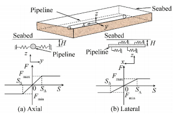 Figure 1 Soil resistance model[21]
 The maximum lateral soil resistance per unit length of pipeline Fmax is expressed by
${F_{\max }} = {N_{ch}}cD + {N_{qh}}\gamma 'HD$
where Nch and Nqh are partial factors. When c=0, Nch=0; otherwise
$\begin{array}{l}{N_{ch}} = 6.75 + 0.07H/D - 11.06/{\left( {H/D + 1} \right)^2} + \\\;\;\;\;\;\;\;\;\;7.12/{\left( {H/D + 1} \right)^3} \le 9\end{array}$
When φ=0, Nqh=0; otherwise
${N_{qh}} = a + b\left( x \right) + c{\left( x \right)^2} + d{\left( x \right)^3} + e{\left( x \right)^4}$
H is embedding depth, and D is pipeline outer diameter. c is soil cohesion, and γ′ is soil sub-weight. The corresponding displacement value SΔ is determined by SΔ=0.04(H+D/2)≤0.1D~0.15D. The values of a, b, c, d, e and x are shown in Table 1.
表 1
20 H/D 2.40 0.44 -0.03 1.06×10⁻³ -1.75×10⁻⁵
25 H/D 3.33 0.84 -0.09 5.61×10⁻³ -1.32×10⁻⁴
30 H/D 4.57 1.23 -0.09 4.28×10⁻³ -9.16×10⁻⁵
35 H/D 6.82 2.02 -0.15 7.65×10⁻³ -1.68×10⁻⁴
40 H/D 10.96 1.78 0.05 -5.43×10⁻³ -1.15×10⁻⁴
45 H/D 17.66 3.31 0.05 -6.44×10⁻³ -1.30×10⁻⁴
Table 1 Value of a, b, c, d, e and x
The maximum axial soil resistance per unit length of pipeline is given by
${f_{\max }} = {\rm{\pi }}D\varepsilon c + {\rm{\pi }}DH\gamma '\tan f\varphi \times \left( {1 + {K_0}} \right)/2$
where ε is scaling factor and can be calculated as follows:
$\begin{array}{l}\varepsilon = 0.608 - 0.123c + 0.274/\left( {{c^3} + 1} \right) + \\\;\;\;\;\;0.695/\left( {{c^3} + 1} \right)\end{array}$
And f is pipeline coating effect factor, and the value of f is listed in Table 2. K0 is the coefficient of earth pressure at rest. The axial displacement, which is used to determine maximum axial soil resistance, depends on soil properties. For dense sand, SΔ=3 mm; for loose sand, SΔ=5 mm; for stiff clay, SΔ=8 mm and for soft clay, SΔ=10 mm.
表 2
1.0 0.9 0.8 0.7 0.6 0.6
Table 2 Values of f for various types of external pipeline coating
2.2 Pipe-soil Interaction Behavior Recommended in the DNV Specification The lateral pipe-soil response model recommended in the DNV specification is based on the failure mechanisms of soil at different stages. In the lateral pipe-soil response model, soil resistance is presumably composed of two parts: pure Coulomb friction and passive resistance induced by the buildup of "berm" as the pipeline moves laterally and penetrates the soil in front of the pipeline[22]. A typical model for passive soil resistance consists of four distinct regions, as displayed in Fig. 2.
Figure 2
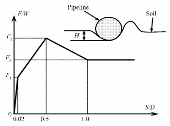 Figure 2 A typical model for passive soil resistance[22]
 As shown in Fig. 2, the typical soil resistance model could be divided into 4 phases based on the ratio of lateral displacement S to the pipelines outer diameter D:1) Elastic region (S/D ≤ 0.02), where stiffness can be set at 50 N/m to 100 N/m for sand and 20 N/m to 40 N/m for clay. This stiffness increases with sand density and the shear strength of clay. 2) Increasing embedment region (0.02 < S/D ≤ 0.5), where the increase in soil resistance and its maximum value (break-out resistance) depends on the accumulated pipeline displacement. 3) Decreasing embedment region (0.5 < S/D ≤ 1), where the break-out value of embedment is linearly reduced by half, and soil resistance decreases accordingly. 4) Constant embedment region (S/D > 1), where embedment and soil resistance are constant.
Passive soil resistance F on per 1 m long pipeline laid on sand can be taken as:
$\frac{F}{{W'}} = \left\{ {\begin{array}{*{20}{c}}\begin{array}{l}\left( {5.0{\kappa _s} - 0.15\kappa _s^2} \right){\left( {H/D} \right)^{1.25}},\\{\kappa _s}{\left( {H/D} \right)^{1.25}},\end{array}&\begin{array}{l}{\kappa _s} \le 26.7\\{\kappa _s} > 26.7\end{array}\end{array}} \right.$ (1)
where κs=γ′D2/W′.
Passive soil resistance F on per 1 m long pipeline laid on clay can be taken as:
$\frac{F}{{W'}} = \frac{{4.1 \cdot {\kappa _s}}}{{G_c^{0.39}}} \cdot {\left( {\frac{H}{D}} \right)^{1.31}},{G_c} = \frac{{{s_u}}}{{D \cdot \gamma '}},{\kappa _c} = \frac{{{s_u} \cdot D}}{{W'}}$ (2)
The symbol W′ means the sub-weight of a 1 m long pipeline section, su is the undrained shearing strength of clay.
2.3 Scale Model Test on Pipe-soil Interaction Modeling tests of pipe-soil interaction were carried out to establish a more suitable pipe-soil interaction model for the engineering case simulation. The sand was obtained from the Bohai Gulf; the internal friction angle φ is 30°, and the dry density is 1.742 g/cm3. The model test system is mainly composed of the test tank, power system, transmission system, and data acquisition system as shown in Fig. 3. The transmission system is composed of a loading frame, lead screw, pushrod, and other mechanical connection devices, which exert pressure on the pipeline. The test tank is composed of toughened glass to store sand and scales with side labels that are used to observe soil movement trends. The data acquisition system consists of displacement and pressure sensors, a dynamic data acquisition instrument, a computer, and high-definition cameras, which record pipeline displacement, soil resistance, and embedment. The modeling pipeline is 160 mm in diameter, 1.0 m long, and weights 4.08 kg.
Figure 3
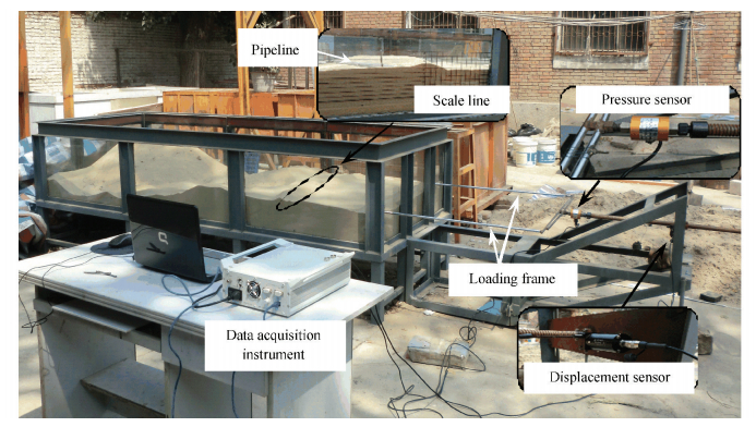 Figure 3 The scale model test system
 A series of model tests on shallow buried pipeline with different initial embedment (H/D=0, H/D=0.25 and H/D=0.5) were proposed. The results are shown in Fig. 4, and the reference value based on DNV code (Formula (1)) is calculated to estimate the correction of test data. In Fig. 4, the horizontal and longitudinal coordinates are dimensionless; the horizontal coordinate is the ratio of lateral displacement to pipeline diameter; and longitudinal coordinate is the ratio of soil resistance to the pipeline's weight.
Figure 4
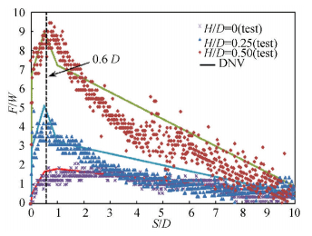 Figure 4 Soil resistance vs. lateral displacement
 Fig. 4 shows that the variation of test data marches well with the calculated value based on DNV specifications. With the increasing initial embedment, the peak value of soil resistance is increasing. But the corresponding lateral displacements when soil resistances reach the peak value are constant, about 0.6D. The residual value of soil resistance for pipelines with different initial embedment is the same. The pipeline with larger initial embedment takes longer lateral displacement to reach the residual value. Based on the test data, the pipe-soil response model (exhibited in Formula (3)) is established by using linear piecewise function fitting.
$\frac{F}{W} = \left\{ {\begin{array}{*{20}{c}}\begin{array}{l}50 \cdot {k_1} \cdot \frac{S}{D},\\\frac{{\left( {S/D - 0.02} \right)}}{{0.58}} \cdot \left( {{k_2} - {k_1}} \right) + {k_1},\\\frac{{\left( {S/D - 0.6} \right)}}{{9.4}} \cdot \left( {{k_3} - {k_2}} \right) + {k_2},\\{k_3},\end{array}&\begin{array}{l}0 \le \frac{S}{D} \le 0.02\\0.02 < \frac{S}{D} \le 0.6\\0.6 < \frac{S}{D} \le 10\\\frac{S}{D} > 10\end{array}\end{array}} \right.$ (3)
where, k1, k2 and k3 is the function of H/D, and
${k_1} = 28{\left( {H/D} \right)^2} - H/D + 0.5$
${k_2} = 14.6\left( {H/D} \right) + 1.71$
${k_3} = 0.24{\left( {H/D} \right)^2} + 0.02\left( {H/D} \right) + 0.63$
3 Critical Buckling State Assessments 3.1 Pipeline Global Buckling Judgment in the DNV Code DNV Classification Notes No. 30.1 < Buckling strength analysis of bars and frames and spherical shells > [23] is the DNV code for the global buckling of structures with high ratios of slenderness. Calculating reduced slenderness λ is the first step in the assessment of pipeline critical global buckling state.
$\lambda = \sqrt {\frac{{{\sigma _y}}}{{{\sigma _E}}}} $ (4)
where symbol σy is yield stress of pipeline; σE is Euler stress, σE=π2E/λk2; λk is flexibility, λk=kL/i. E is elasticity modulus of pipeline. k is length reduction factor, determining by endpoints boundary condition. L is the buckling length. Critical reduced slenderness λ0 is then selected according to structure type, and critical buckling stress σacr is determined by using Formula (5):
$\frac{{{\sigma _{{\rm{acr}}}}}}{{{\sigma _y}}} = \left\{ \begin{array}{l}1.0,\;\;\;\;\;\lambda \le {\lambda _0}\\\frac{{1 + 0.5\left( {\lambda - {\lambda _0}} \right) + {\lambda ^2} - \sqrt {{{\left( {1 + 0.5\left( {\lambda - {\lambda _0}} \right) + {\lambda ^2}} \right)}^2} - 4{\lambda ^2}} }}{{2{\lambda ^2}}},\;\;\;\;\lambda > {\lambda _0}\end{array} \right.$ (5)
If the stress is greater than σacr, global buckling has occurred in the pipeline.
DNV also published the DNV-RP-C202 < Design of offshore steel structures, general (load and resistance factor design method) > [24] to estimate the stability of lateral global buckling in pipelines experiencing different external and internal pressures. This code categorizes load into axial compressive (tensile), bending moment, torsion, and shear forces. Section size, material properties, and the difference in dominant load are considered as well. The first step in assessing buckling stability is to calculate the axial compressive stress σa and buckling strength fkcd of the design by using Formulas(6) and (7).
${\sigma _{\rm{a}}} = \frac{{P + {p_{\rm{e}}}{A_{\rm{e}}} + {p_{\rm{i}}}{A_{\rm{i}}}}}{A}$ (6)
${f_{{\rm{kcd}}}} = \frac{{{f_{{\rm{kc}}}}}}{{{\gamma _{\rm{M}}}}}$ (7)
where pe is external pressure, and pi is internal pressure. Ae is external cycle area, and Ai is internal cycle area. γM is material factor, γM=1.15; fkc is characteristic buckling strength,
${f_{{\rm{kc}}}} = \left\{ {\begin{array}{*{20}{c}}{\left( {1.0 - 0.28{{\bar \lambda }^2}} \right){f_{{\rm{ak}}}},\;\;\;\;\bar \lambda \le 1.34}\\{\frac{{0.9}}{{{{\bar \lambda }^2}}}{f_{{\rm{ak}}}},\;\;\;\;\;\;\;\bar \lambda > 1.34}\end{array}} \right.$
$\bar \lambda = \frac{{kL}}{{{\rm{ \mathsf{ π} }} \cdot i}}\sqrt {\frac{{{f_{{\rm{ak}}}}}}{E}} $
Design stress is then determined by using circumferential direction σh, design stress caused by global bending σm, and local buckling strength of the design fakd.
${\sigma _h} = \frac{{r \cdot \left( {{p_{\rm{i}}} - {p_{\rm{e}}}} \right)}}{t}$ (8)
${\sigma _m} = \frac{M}{{{\rm{ \mathsf{ π} }}{r^2}t}}$ (9)
${f_{{\rm{akd}}}} = \frac{{{f_{{\rm{ak}}}}}}{{{\gamma _{\rm{M}}}}} = \frac{1}{{{\gamma _{\rm{M}}}}} \cdot \frac{{b + \sqrt {{b^2} - 4ac} }}{{2a}}$ (10)
where
$a = 1 + {\sigma _y}^2/{f_{Ea}}^2$
$b = \left( {2{\sigma _y}^2/{f_{Ea}}{f_{Eh}} - 1} \right) \cdot {\sigma _h}$
$c = \sigma _h^2 + {\sigma _y}^2{\sigma _h}^2/f_{Eh}^2 - \sigma _y^2$
Elastic buckling strength for axial force
$\begin{array}{l}{f_{Ea}} = \\\sqrt {1 + {{\left[ {0.5{{\left( {1 + r/150t} \right)}^{ - 0.5}} \times 0.702\sqrt {1 - {\nu ^2}} \cdot {L^2}/rt} \right]}^2}} \times \\\left( {{{\rm{ \mathsf{ π} }}^2}E/\left[ {12 \cdot \left( {1 - {\nu ^2}} \right)} \right]} \right) \times {\left( {t/r} \right)^2}\end{array}$
Elastic buckling strength for circumferential compression fEh=0.25E(t/r)2.
The stability requirement for pipelines subjected to axial compression, bending, and circumferential compression is expressed by Formula (11).
$\frac{{{\sigma _a}}}{{{f_{{\rm{kcd}}}}}} + \frac{{{\sigma _m}}}{{{f_{{\rm{akd}}}}\left( {1 - \frac{{{\sigma _a}}}{{{\sigma _E}}}} \right)}} \le 1$ (11)
Submarine pipeline will not exhibit global buckling if formula (11) is satisfied.
3.2 Engineering Case Study A project in the Bohai Gulf is used to calculate the critical buckling force. Table 3 shows the pipeline design parameters. The critical buckling forces of ideal and imperfect pipelines are calculated with different methods.
表 3
0.273 1 0.020 6 7 850 2.07×10¹¹ 1.17×10⁻⁵ 0.3 87.7 12.7 448
Table 3 Pipeline design parameters
3.2.1 Critical buckling force of an ideal pipeline Analytical method, standard method and finite element analysis are used to calculate the critical buckling forces of pipelines at different lengths ranging from 10 m to 250 m at 2 m intervals. The relationship between critical buckling force and length is depicted in Fig. 5. The classical first-order solution developed by Hobbs (1984) for analysis is adopted in this study DNV-RP-C202 and DNV Classification Note No. 30.1 are used in the standard method. In the FEA, the Buckle method based on ABAQUS software is utilized. This method can estimate the critical force of the ideal structure and provides a reference for the calculation of structural stability.
Figure 5
 Figure 5 The development of critical buckling force with increasing buckling length
 Fig. 5 shows that critical buckling force decreases with the increasing buckling length. The development trends of the results calculated with the analytical, FEA, and DNV-RP-C202 methods are consistent. The result obtained by using DNV Classification Note No. 30.1 underestimates critical force when buckling length is short; and it overestimates critical force when the length is long enough. DNV Classification Note No. 30.1 is unsuitable for the analysis of long structures buckling stability, especially for submarine pipelines. In the comparison of the results of the three methods, the value obtained by using the analytical method is the largest, followed by the FEA result and that calculated by using DNV-RP-C202. This is because that the analytical method is based on small-deflection theory, which is accurate in small deformation analysis but encounters errors in large-deflection analysis. The lack of a reserve safety margin in the analytical result is also a factor. The influences of a reserve safety margin and manufacturer imperfections (V0/L0 ≤ 1.5‰, V0 is an amplitude of initial imperfection. L0 is length of imperfection) are considered in the value calculated by using DNV-RP-C202; thus, this result is the smallest. The Buckle method analyzes the critical buckling force of the ideal pipeline and neglects soil resistance. Therefore, the result is between the analytical and FEA values. The FEA method can optimize engineering designs by refining the interaction and boundary conditions.
3.2.2 Critical buckling force of imperfect pipelines The ABAQUS/explicit simulation method was used to analyze the critical buckling force of imperfect pipelines. Initial imperfections were introduced based on the modal analysis result. The ideal pipeline was analyzed using a "buckle" step to generate a first-order eigenvalue offset. The offset values of each point in the bending pipeline section were printed into a record file. Then the scaling factor was calculated and the factor value equaled to the ratio of imperfection amplitude to the first-order eigenvalue offset. Before proposing former buckling analysis, the record file is called to generate an initial offset of all points in imperfect pipeline section in the buckling analysis model, and the actual initial offset value is scaled based on the scaling factor calculated above. The initial perfection shape introduced by this method is more reasonable based on the probability. The imperfection curve is smooth and has better convergence. The whole analysis process contains two steps. (1) The first step is applying gravity load to make the pipeline contact with the seabed. (2) The second step is applying temperature and pressure difference load. The temperature load was applied by applying a temperature field to the whole pipeline and changed the temperature field value from 0 to 87.7 ℃ in this step. The seabed simulated without any temperature field will be considered a 0 ℃ temperature part in analysis. Since the pipeline was simulated as a beam section, the pressure difference cannot be applied directly. The pressure load can be considered as an equivalent temperature load calculated[1] according to this formula ΔT′=(pi-pe)D(0.5-v)/2Eαt. The value of the equivalent temperature load is 6.95 ℃. Therefore, the final value of temperature field applied on the whole pipeline is 94.65 ℃. The interaction between pipeline and seabed soil was simulated separately in the normal direction and tangential direction. The "hard" contact was used in the vertical direction, and the normal interaction force can be passed to each other between seabed and pipeline. The user subroutine VFRIC was used to simulate the tangential interaction behavior. The subroutine VFRIC allows user to define a more complex shear force relationship between contacting surfaces. The value of shear force can be modified based on the contact pressure, surface state value, relative displacement and so on. In this analysis, formula (3) is chose as the governing equation of the subroutine VFRIC. Therefore, the soil resistance on pipeline was calculated based on the initial embedment H/D, pipeline self-weight and lateral displacement. The soil resistances on pipeline sections exhibiting different lateral displacement were different.
Based on the sizes, the imperfections were divided into small imperfections (V0/L0 ≤ 1.5‰) and large imperfections (V0/L0 > 1.5‰). Five pipelines with different initial imperfection sizes are analyzed, and the parameters are shown in Table 4. Fig. 5 shows the critical buckling force of the five pipelines.
表 4
1 56 56 1 214.50
2 96 64 1.50 143.75
3 346 88 3.93 53.50
4 396 92 4.30 52.13
5 496 96 5.17 50.00
Table 4 Imperfect pipeline critical buckling force (FEA results)
Table 4 and Fig. 5 show that critical buckling force decreases rapidly when the initial imperfection size is greater than the limit of manufacture imperfection. The critical buckling force of pipelines with small imperfections (model No. 1 and 2) is lower than the analytical results and larger than the force calculated based on code DNV-RP-C202. While the critical buckling force of pipelines with large imperfections (model No. 3, 4, and 5) is lower than force calculated based on code DNV-RP-C202. That is to say the imperfections can reduce the critical buckling forces but the critical forces for pipelines with small imperfections are still within the range limited by analytical results and code results. The critical buckling forces of pipelines with small imperfections (V0/L0 ≤ 1.5‰) are similar to the ideal pipelines. The code results line is the upper limit line for critical buckling force of pipelines with large imperfections (V0/L0 > 1.5‰). Once we know the size of pipeline imperfections and the magnitude of load, we can judge whether the pipeline exhibits buckling or not by comparing the pipeline load with the analytical calculation results and the code results.
The method that utilizes the limits determining the occurrence of global buckling is applied to the engineering case in this study. In the case, the imperfections were not set in pipeline laying process. Thus, initial imperfection size should be smaller than V0/L0=1.5‰. The effective axial force P=EAαT+ApD(0.5-ν)/(t/2)=3.75 MN, which is greater than the critical force determined by using the analytical method (0.535 MN). Therefore, the occurrence of global buckling can be determined. Further post-buckling analysis is required to assess pipeline damage risk in the buckling process.
4 Critical Failure State Assessments for Post-buckling Pipeline In the pipeline global buckling process, large bending moments and compressive strain accumulate in the cross-section. Both of them can lead to damage of the pipeline section. Thus, critical pipeline failure state can also be divided into two categories: critical load limit state and critical deformation limit state.
4.1 Critical Load Limit State The excessive bending moments caused by the bending of the buckling section threaten the safety of the pipeline system. The critical load limit state should consider the combined effect of axial force and bending moment. The DNV code concludes a limit value of the load combination in the most seriously deformed section[25]. The assessment process begins by calculating flow stress parameter αc, yield axial force Sp, and yield bending moment Mp as follows:
${\alpha _c} = \left( {1 - \beta } \right) + \beta \frac{{{f_u}}}{{{f_y}}}$ (12)
${S_p} = {f_y}{\rm{ \mathsf{ π} }}\left( {D - t} \right) \cdot t$ (13)
${M_p} = {f_y}{\left( {D - t} \right)^2}t$ (14)
where coefficient β=(60-D/t)/90; characteristic yield stress fy=σy-fy, temp, fy, temp is de-rating values due to the temperature of yield stress; characteristic tensile strength fu=σu-fu, temp, fu, temp is de-rating values due to the temperature of tensile strength.
On the basis of the relative weight of internal and external pressures, the appropriate Formula to assess the post-buckling pipeline is selected from Formulas (15) and (16). Submarine pipeline buckling is not damaged if inequality is established.
If internal pressure is greater than external pressure, Formula (15) is used to assess the pipeline.
${\left\{ {{\gamma _m}{\gamma _{SC}}\frac{M}{{{\alpha _c}{M_p}}} + {{\left\{ {\frac{{{\gamma _m}{\gamma _{SC}}P}}{{{\alpha _c}{S_p}}}} \right\}}^2}} \right\}^2} + {\left( {{\alpha _p}\frac{{{p_{\rm{i}}} - {p_{\rm{e}}}}}{{{\alpha _c}{p_b}\left( t \right)}}} \right)^2} \le 1$ (15)
where γm is material factor; γSC is safety class resistance factor; pb is pressure containment resistance,
If internal pressure is lower than external pressure, Formula(16) is used to evaluate the pipeline.
${\left\{ {{\gamma _m}{\gamma _{SC}}\frac{M}{{{\alpha _c}{M_p}}} + {{\left\{ {\frac{{{\gamma _m}{\gamma _{SC}}P}}{{{\alpha _c}{S_p}}}} \right\}}^2}} \right\}^2} + {\left( {{\gamma _m}{\gamma _{SC}}\frac{{{p_{\rm{e}}}}}{{{p_{\rm{c}}}}}} \right)^2} \le 1$ (16)
where pc is collapse pressure.
If the pipeline is under a lateral point load in addition to axial load, pressure, and bending moment, plastic moment capacity M′p should be modified as follows:
${{M'}_p} = {M_p} \cdot {\alpha _{{\rm{pm}}}}$ (17)
where αpm is plastic moment reduction factor, αpm=1-D·R/(130·t·Ry); R is reaction force from point load, Ry=3.9fy·t2.
4.2 Critical Deformation Limit State Large deformations occur in post-buckling pipelines and influence their integrity. DNV provides different limit values according to the relative weights of internal and external pressures; when the internal pressure is greater than the external pressure, the calculation formula is as follows:
$\varepsilon \le {\varepsilon _{Rd}} = \frac{{{\varepsilon _c}\left( {t,{p_{\min }} - {p_{\rm{e}}}} \right)}}{{{\gamma _\varepsilon }}}$ (18)
$\begin{array}{l}{\varepsilon _c}\left( {t,{p_{\min }} - {p_{\rm{e}}}} \right) = 0.78\left( {\frac{t}{D} - 0.01} \right) \cdot \\\;\;\;\;\;\;\;\;\left( {1 + 5.75\frac{{{p_{\min }} - {p_{\rm{e}}}}}{{{p_b}\left( t \right)}}} \right){\alpha _h}^{ - 1.5}{\alpha _{gw}}\end{array}$ (19)
where ε is design compressive; εRD is limit compressive; γε is safety class resistance factor; pmin is minimum internal pressure that can be continuously sustained with the associated strain; αh is train hardening, αh=0.93; girth weld factor αgw=1.0.
When the internal pressure is lower than the external pressure, the calculation formula is as follows:
${\left( {\frac{{{\varepsilon _{sd}}}}{{\frac{{{\varepsilon _c}\left( {t,0} \right)}}{{{\gamma _\varepsilon }}}}}} \right)^{0.8}} + \frac{{{p_{\rm{e}}} - {p_{\min }}}}{{\frac{{{p_c}\left( t \right)}}{{{\gamma _m}{\gamma _{SC}}}}}} \le 1$ (20)
${\varepsilon _c}\left( {t,0} \right) = 0.78 \cdot \left( {\frac{t}{D} - 0.01} \right) \cdot \alpha _h^{ - 1.5}{\alpha _{gw}}$ (21)
4.3 Engineering Case Study The engineering case is evaluated based on critical and deformation failures by using the analytical and FEA methods.
4.3.1 Calculation of axial force and bending moment of post-buckling pipelines (1) Analytical method
The third-order analytical solution presented by Liu[26] is adopted in this approach. Buckling length can be calculated by using Eq.(22) when imperfect pipelines are generated by third-order buckling.
$\begin{array}{l}EA\alpha T = 45.95\frac{{EI}}{{{L^2}}} \times \left[ {1 - \frac{{{R_3}}}{{26\;995.18}}{{\left( {\frac{{{L_0}}}{L}} \right)}^2}} \right] + \\\;\;\;\;\;\;\;\;\;\;\;\;\left[ {278.290\;06 \times {{10}^{ - 6}}\frac{{A{\mu _A}}}{E}{{\left( {\frac{{{\mu _L}}}{I}} \right)}^2}{q^3}{L^7} - } \right.\\\;\;\;\;\;\;\;\;\;\;\;\;\left[ {30.895\;8 \times {{10}^{ - 6}}\frac{{A{\mu _A}}}{E}{{\left( {\frac{{{\mu _A}L}}{I}} \right)}^2}{q^3}{L_0}^7 - } \right.\\\;\;\;\;\;\;\;\;\;\;\;\;{\left. {{{\left( {\frac{{{\mu _A}qL}}{2}} \right)}^2}} \right]^{\frac{1}{2}}}\end{array}$ (22)
$\begin{array}{l}{R_3} = 420.7901 \times \left( {\frac{{{L_0}}}{L}} \right) + 2083.1981 \times \frac{1}{{{{\left( {\frac{{{L_0}}}{L}} \right)}^2} - 1}} \times \\\;\;\;\;\;\left[ {\left[ {{{\left( {\frac{{{L_0}}}{L}} \right)}^2} \times 0.9981 \times \sin \left( {2.9356\frac{{{L_0}}}{L}} \right) - } \right.} \right.\\\;\;\;\;\;\left. {\frac{{{L_0}}}{L} \times 0.0512 \times \cos \left( {2.9356\frac{{{L_0}}}{L}} \right)} \right] - 546.4489 \times \\\;\;\;\;\;\left. {\left[ { - 0.0512 \times \left( {\frac{{{L_0}}}{L}} \right) - \sin \left( {2.9356 \times \frac{{{L_0}}}{L}} \right)} \right]} \right]\end{array}$ (23)
where μA is axial soil resistance coefficient, and μL is lateral soil resistance coefficient
Axial force and bending are then computed by using Formulas (24) and (25).
$P = 34.45\frac{{EI}}{{{L^2}}} \times \left[ {1 - \frac{{{R_3}}}{{20244.23}} \times {{\left( {\frac{{{L_0}}}{L}} \right)}^2}} \right]$ (24)
${M_m} = - 0.139\;60{\varphi _L}q\left( {{L^2} - {L_0}^2} \right)$ (25)
(2) FEA method
The explicit method is used to model pipeline buckling. The pipeline length is 1 km, and imperfection is introduced in the middle of the pipeline. The pipeline is simulated with Pipe31 elements, and the lateral and axial displacements on both ends of the pipeline are constrained. The pipeline is meshed using 1 m intervals. The soil is simulated in C3D8R elements with a fixed constraint at the bottom and a lateral constraint on the sides of the horizontal displacement. The soil is 10 m wide, 1 m deep and 1000 m length, and is meshed in the lateral and axial directions in 1 m increments, and in 0.5 m increments in the vertical direction. The initial imperfection was introduced with the same way described in buckling analysis section before the start of analysis process. The amplitude of initial imperfection is 0.096 m, and the imperfection length is 64 m. The whole analysis process was same as it in the buckling analysis. Applying gravity load first and then applying temperature and equivalent temperature load. The interaction constitution model was also same as before. The pipeline is shallowly embedded and the initial embedment H/D is 0.2. Therefore, the soil resistance on pipeline can be calculated according to formula (3). The analysis model is displayed in Fig. 6.
Figure 6
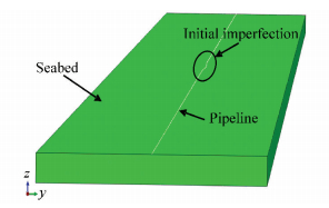 Figure 6 Finite element analysis model
 The reliable of numerical simulation model was verified before buckling analysis. Scale model test data[27] is used to calibrate the model. The same simulation method is used to analyze the test with the parameters of test pipeline and resistance. Fig. 7 shows the comparison between FEA result and test data.
Figure 7
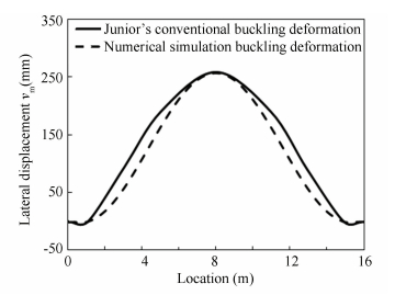 Figure 7 FEA model calibration
 Fig. 7 shows that the difference between test data and FEA result is little. The maximum lateral displacements for the two methods are almost the same. The numerical simulation method is reliable.
The contour plot of the axial force in the pipeline is given in Fig. 8, and tensile force is designated as positive. This plot shows that the axial compressive force of a deformed pipeline decreases and that the minimum compressive force that occurs in the middle of the pipeline is approximately 0.262 MN.
Figure 8
 Figure 8 Axial force along the post-buckling pipeline
 The distribution of bending moment in the pipeline is presented in Fig. 9. The bending moment of a deformed pipeline increases, and the maximum bending moment that occurs in the middle of the pipeline is approximately 0.33 MN·m.
Figure 9
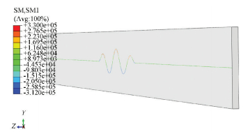 Figure 9 Bending moment along the post-buckling pipeline
 The distribution of axial strain in the pipeline is exhibited in Fig. 10. The axial strain of a deformed pipeline increases, and the maximum axial strain is approximately 0.243%.
Figure 10
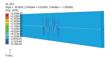 Figure 10 Axial strain along the post-buckling pipeline
 4.3.2 Assessment of post-buckling pipeline failure (1) Assessment based on critical load failure in lateral buckling.
The bending moment and axial compressive force are 4.05×10⁵ N·m and 1.46×10⁵ N, respectively, as determined by the analytical method. By substituting these values into the left-hand side of Formula (15), we can obtain a result of 0.626. This value is lower than 1, thus indicating that the pipeline is undamaged. The bending moment and axial compressive force are 3.33×10⁵ N·m and 2.62×10⁵ N, respectively, according to the FEA method. By substituting these values into the left-hand side of Formula (15), we can obtain a result of 0.423. This value is lower than 1, thus suggesting that the pipeline is undamaged.
(2) Assessment based on critical deformation failure in lateral buckling.
Axial strain is 0.244% according to the FEA method. By substituting this result into Formula (18), we obtain ε = 0.244% < εRd = 2.2%; therefore, the pipeline is undamaged.
4.4 Analysis of the Two Different Critical Failures To determine the stricter of the two critical failures discussed above, additional FEA is conducted by increasing the temperature of the pipeline. The analysis result is shown in Fig. 11. The horizontal coordinate is the temperature difference and the longitudinal coordinate is the ratio of actual failure assessment index to critical failure assessment value according to various critical failures.
Figure 11
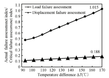 Figure 11 Critical state discussion under two different critical failures
 As shown in Fig. 11, the internal force of the section increases rapidly as the temperature difference increases, whereas axial strain increases gradually. When the pipeline experiences critical load failure at 170 ℃, the pipeline is damaged; however, on the basis of critical displacement failure, the pipeline is unscathed. Thus, load failure is stricter than displacement failure in the assessment of failure in post-buckling pipelines.
5 Conclusions The assessment of critical buckling state for as-laid pipeline and critical failure state for post-buckling pipeline were analyzed. As a most important key parameter in pipeline global buckling analysis, the soil resistance was also discussed. The main conclusions were as followed.
1) A pipe-soil dynamic response model was proposed based on the model test data. With increasing initial embedment, the peak value of soil resistance increases, while the lateral displacement for different embedded pipelines to reach the peak value is constant, about 0.6D. The residual soil resistances on pipeline do not change with the varying initial embedment and it is only determined by the pipeline's weight.
2) The critical buckling force of an engineering case was calculated with different methods including analytical method, standards and finite element simulation method. The comparison shown that the critical buckling force decreases with increasing buckling length and imperfection size. Small imperfection (0 ≤ V0/L0 ≤ 1.5‰) has little effect in reducing critical buckling force. The critical force of ideal pipeline and pipeline with small imperfection (0 ≤ V0/L0 ≤ 1.5‰) is lower than analytical calculation and higher than result calculated based on standard.
3) Post-buckling pipeline failure is assessed based on critical load and displacement failures, and the difference between these two failures criteria is analyzed. The results indicate that critical load failure is stricter than critical displacement failure and should be the primary reference standard.
References
[1] Hobbs R E. In-service buckling of heated pipelines. Journal of Transportation Engineering, 1984, 110(2): 175-189. DOI:10.1061/(ASCE)0733-947X(1984)110:2(175) (
 0)
0)[2] Taylor N, Gan A B. Submarine pipeline buckling—imperfection studies. Thin-Walled Structures, 1986, 4(4): 295-323. DOI:10.1016/0263-8231(86)90035-2 (
 0)
0)[3] Konuk I, Yu S. Continuum FE modeling of lateral buckling: Study of soil effects. In: Offshore Technology Conference. Houston, 2007.347-354, DOI: 10.1115/OMAE2007-29376. (
 0)
0)[4] Wang D, White D J, Randolph M F. Large-deformation finite element analysis of pipe penetration and large-amplitude lateral displacement. Canadian Geotechnical Journal, 2010, 47(8): 842-856. DOI:10.1139/T09-147 (
 0)
0)[5] Hong Z H, Liu R, Liu W B, et al. Study on lateral buckling characteristics of a submarine pipeline with a single arch symmetric initial imperfection. Ocean Engineering, 2015, 108: 21-32. DOI:10.1016/j.oceaneng.2015.07.049 (
 0)
0)[6] Brennodden H, Sveggen O, Wagner D A, et al. Full-scale pipe-soil interaction tests. In: Offshore Technology Conference. Houston: Offshore Technology Conference. DOI: 10.4043/5338-MS. (
 0)
0)[7] Bruton D A S, White D J, Cheuk C Y, et al. Pipe-soil interaction behaviour during lateral buckling. SPE Projects, Facilities & Construction, 2006, 1(3): 1-9. DOI:10.2118/106847-PA (
 0)
0)[8] Liu R, Yan S W, Wu X L. Model test studies on soil restraint to pipeline buried in Bohai soft clay. Journal of Pipeline Systems Engineering and Practice, 2012, 4(1): 49-56. DOI:10.1061/(ASCE)PS.1949-1204.0000109 (
 0)
0)[9] Bransby M F, Newson T A, Brunning P. Centrifuge modelling of the upheaval capacity of pipelines in liquefied clay. In: 12th International Offshore and Polar Engineering Conference, Kitakyushu: International Society of Offshore and Polar Engineers, 2002. 100-107. (
 0)
0)[10] Cheuk C Y, Take W A, Bolton M D, et al. Soil restraint on buckling oil and gas pipelines buried in lumpy clay fill. Engineering Structures, 2007, 29(6): 973-982. DOI:10.1016/j.engstruct.2006.06.027 (
 0)
0)[11] Wang L, Liu R. The effect of a berm on the lateral resistance of a shallow pipeline buried in sand. Ocean Engineering, 2016, 121: 13-23. DOI:10.1016/j.oceaneng.2016.05.010 (
 0)
0)[12] Figueiredo F C, Borges L A, Pontes I D S, et al. Limit analysis on evaluation of lateral resistance of partially embedded pipes with frictional pipe-soil interface. 8th International Conference on Computational Plasticity. Fundamentals and Applications. COMPLASXIII.2015.530-541. (
 0)
0)[13] McCarron W O. Limit analysis and finite element evaluation of lateral pipe-soil interaction resistance. Canadian Geotechnical Journal, 2015, 53(1): 14-21. DOI:10.1139/cgj-2014-0409 (
 0)
0)[14] Reng Y R. The application of ABAQUS software in the pipe/soil interaction. China Offshore Platform, 2007, 22(4): 48-51. (
 0)
0)[15] Jukes P, Eltaher A, Sun J. The latest developments in the design and simulation of deepwater subsea oil and gas pipelines using FEA. In: 3rd ISOPE International Deep-Ocean Technology Symposium, Beijing: International Society of Offshore and Polar Engineers, 2009.70-82. (
 0)
0)[16] Pike K, Duan G, Sun J, et al. Comprehensive FEA of thermal mitigation Buoyancy Module (TMBM)-Soil interaction using the Coupled Eulerian-Lagrangian (CEL) method. In: 29th International Conference on Ocean, Offshore and Arctic Engineering: Volume 5, Parts A and B. American Society of Mechanical Engineers. 2010. 865-870. DOI: 10.1115/OMAE2010-20885. (
 0)
0)[17] Chee K Y, Walker A. Assessment of Numerical Modelling of Pipeline Lateral Buckling. In: SUT Symposium of Lateral Buckling, Australia. 2011. (
 0)
0)[18] Sun J, Jukes P. From Installation to Operation: A Full-Scale Finite Element Modeling of Deep-Water Pipe-in-Pipe System. In: 28th International Conference on Ocean, Offshore and Arctic Engineering, Honolulu: American Society of Mechanical Engineers. 2009. 439-446. DOI: 10.1115/OMAE2009-79519. (
 0)
0)[19] Bruton D A S, White D J, Carr M, et al. Pipe-soil interaction during lateral buckling and pipeline walking-The SAFEBUCK JIP. In: Offshore Technology Conference, Houston: Offshore Technology Conference. 2008. OTC 19589. DOI: 10.4043/19589-MS. (
 0)
0)[20] Hong Z H, Liu R, Liu W B, et al. A lateral global buckling failure envelope for a high temperature and high pressure (HT/HP) submarine pipeline. Applied Ocean Research, 2015, 51: 117-128. DOI:10.1016/j.apor.2015.02.008 (
 0)
0)[21] Alliance A L. Guidelines for the Design of Buried Steel Pipe. American Society of Civil Engineers, 2005. (
 0)
0)[22] Det Norske Vertias. DNV-RP-F109. On-Bottom Stability Design of Submarine Pipelines.Norway: Det Norske Vertias. 2011. (
 0)
0)[23] Det Norske Vertias. DNVClassification Notes No.30.1. Buckling strength analysis of bars and frames, and spherical shells. Norway: Det Norske Vertias. 2004. (
 0)
0)[24] Det Norske Veritas. DNV-RP-C202. Buckling Strength of Shells. Norway: Det Norske Veritas, 2013. (
 0)
0)[25] Det Norske Veritas. DNV-OS-F101. Submarine Pipeline Systems. Norway: Det Norske Veritas, 2012. (
 0)
0)[26] Liu W. Study on Lateral Global Buckling of HP/HT Deep Water Pipeline. Tianjin: Tianjin University, 2015. (
 0)
0)[27] Junior E P, da Rocha R S, da Costa Á M, et al. Experimental tests and numerical simulation in a reduced model in a pipeline with ZIG-ZAG geometry: A parametric study.2004 International Pipeline Conference. American Society of Mechanical Engineers, 2004. 399-407. DOI: 10.1115/IPC2004-0423. (
 0)
0)