 ,1, Ruoyu Liang11School of Electrical and Electronic Engineering,
 2Hebei Key Laboratory of Power Internet of Things Technology,
3Baoding Key Laboratory of Optical Fiber Sensing and Optical Communication Technology,
Received:2021-03-06Revised:2021-05-15Accepted:2021-05-17Online:2021-06-25

Abstract
Keywords:
PDF (2768KB)MetadataMetricsRelated articlesExportEndNote|Ris|BibtexFavorite
Cite this article
Lijuan Zhao, Haiying Zhao, Zhiniu Xu, Ruoyu Liang. A design of novel photonic crystal fiber with low and flattened dispersion for supporting 84 orbital angular momentum modes. Communications in Theoretical Physics, 2021, 73(8): 085501- doi:10.1088/1572-9494/ac01db
1. Introduction
With the development of the communication industry, the demand for channel capacity has increased correspondingly, and multiplexing technology has been widely used to improve the communication capacity. Besides sensing [1–3], optical fiber has been widely used in communication. Although the capacity of a traditional communication system based on a single-mode fiber is increasing, which cannot break the Shannon limit due to the confinement of the nonlinear effect [4]. The technology of space division multiplexing (SDM) has been increasing in popularity as the way with the most potential to keep up with the capacity demand of an optical communication system [5]. SDM can multiplex channel in multi-core or multi-mode fiber by using the freedom degree of fiber in space. Mode division multiplexing (MDM) of orbital angular momentum (OAM) is an important method to realize SDM, in which OAM beams with different topological charge numbers are used as information carriers [6]. Because OAM modes theoretically have infinite topological charges and different OAM modes are orthogonal to each other, the capacity and efficiency of optical communication can be enhanced greatly [7]. In 2012, J Wang et al demonstrated multiplexing/demultiplexing of four polarization-multiplexed (pol-muxed) OAM beams, showed scalability in the spatial domain using two groups of concentric rings of eight pol-muxed OAM beams, reported data exchange between two OAM beams and demonstrated that OAM could be a useful degree of freedom for increasing the capacity of free-space communications [8].The number of supported OAM modes, confinement loss and dispersion are key parameters in optical communication system. In order to increase OAM modes and improve optical properties, researchers have designed, fabricated or studied a variety of fibers, such as twisted air-core fibers [9–11], ring fibers [12–14] and doped fibers [15–17]. They all have large difference of effective refractive index between adjacent eigenmodes and confine the energy in the ring with high refractive index. However, these ring-core fibers require very high doping and precise control of thin refractive index rings. It undoubtedly brings higher loss and poses difficulty to the fabrication. Moreover, high refractive index is limited to thin ring may reduce the effective mode area and result in unexpected nonlinearity. Compared with conventional fiber, photonic crystal fiber (PCF) displays some distinct optical properties through ingeniously engineering its structure, such as controllable nonlinearity, adjustable dispersion and low confinement loss [18]. Its application in the transmission of OAM has attracted wide attention. In 2016, H Li et al [19] proposed a hollow-core photonic bandgap fiber which can support 16 OAM modes, but its confinement loss is pretty high. In 2017, H Zhang et al [20] designed a circular PCF supporting good-quality OAM mode transmission, but it only supports 42 OAM modes. In 2018, N Ashok et al [21] proposed a novel PCF structure with spirally arranged air holes in the cladding, which can only support 14 OAM modes in spite of the nonlinearity coefficient is as low as 2.78 W−1·km−1. X Bai et al [22] proposed a PCF with square air holes which can support 46 OAM modes, but the confinement loss is about 10−7 dB m−1. In 2020, W Wang et al [23] proposed a dual-guided PCF through doping Schott SF6 in Schott LLF1, supporting 56 OAM modes and four linear polarization (LP) modes, but the values of OAM mode purity are low. M M Hassan et al [24] designed a PCF with chain shaped air cavities, supporting 26 OAM modes and having low dispersion variation of 3.8684 ps·km−1·nm−1. M A Kabir et al [25] designed a PCF by Bezier polygon with four cartesian control points and four uniform weights. Although it has low confinement loss and nonlinearity coefficient, supporting only 38 OAM modes. In the same year, M A Kabir et al [26] designed a spider web shaped PCF. At the wavelength of 1550 nm, the nonlinearity coefficient of most modes ranges from 2 W−1·Km−1 to 3 W−1·km−1, but only 26 OAM modes are supported. And F. A. Al-Zahrani [27] designed two guided modes regions ring-core PCFs, the background and ring-core materials of the proposed PCF are silicon and Shcott sulfur difluoride (SF2) glass. Although the mode quality is as high as 96% and the isolation parameter (ISO) is kept above 72 dB, the number of OAM modes is 76 which is still needs to be further improved. Therefore, it is necessary to design a novel fiber with better performance for OAM modes transmission.
In this paper, a novel dual-guided PCF is proposed. The proposed PCF is composed of three layers of circular air holes and four layers of rectangular air holes. The model is constructed by the finite element method (FEM). The optical properties and propagation properties of the proposed PCF are systematically analyzed through the numerical analysis of electromagnetic field. The results reveal that the proposed PCF can support up to 84 OAM modes, the purity of each mode is larger than 91.7% and the maximum ISO is up to 145 dB. Additionally, the designed PCF provides large effective mode area, low nonlinearity coefficient and confinement loss, flattened and low dispersion. Therefore, it could be used in optical fiber communication system with large capacity and high requirements of performance.
2. Design methodology of PCF
2.1. Structure of PCF
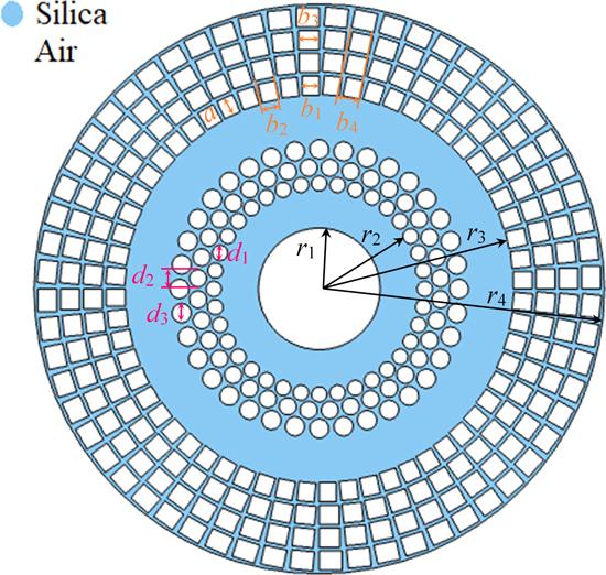
In order to transmit OAM modes, fibers should satisfy two characteristics. One is the designed PCF should have a circular refractive index profile and another is the structure should maintain a large difference of effective refractive index (Δneff>10−4) between adjacent eigenmodes. Otherwise, modes supported by the fiber are easily coupled into LP modes [28].In order to meet above requirements, a novel PCF with circular and rectangular air holes is designed in this paper after taking into account the properties such as the number of supported OAM modes, ISO, dispersion and confinement loss. And silica with refractive index of 1.45 is selected as the background material, as shown in figure 1, blue area represents silica and white area represents air. The proposed PCF has two rings to guide OAM modes, in which the radius of core (r1) is 3.2 μm, the radius of the inner ring (r2) is 5 μm, the radius of the outer ring (r3) is 10 μm and the radius of the fiber (r4) is 15 μm. There are three layers of air holes between the inner ring and the outer ring, those are used to separate regions guided modes and adjust the propagation properties of the inner ring. The diameter of circular air holes in the cladding, that is, d1, d2 and d3 are 0.8 μm, 0.9 μm and 1 μm, respectively. The number of circular air holes in each layer (N1) is 36. There are four layers of rectangular air holes with circular distribution around the outer ring. The length of all rectangular air holes (a) is 1 μm. The width of rectangular air holes in each layer, that is, b1, b2b3 and b4 are 0.9 μm, 1.05 μm, 1.1 μm and 1.2 μm, respectively. The number of rectangular air holes in each layer (N2) is 60.
Figure 1.
 New window|Download| PPT slide
Figure 1.Schematic diagram of the proposed PCF.
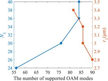
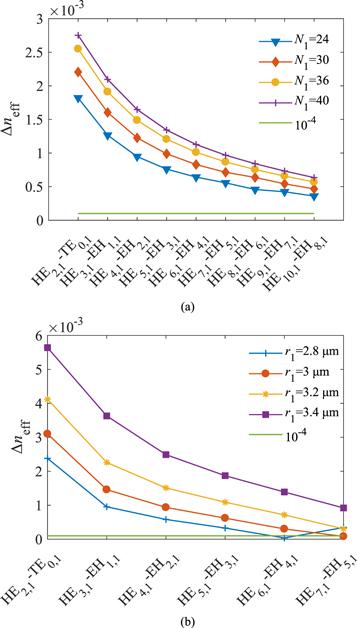
The reason why rectangular air holes are designed instead of circular air holes is that the air-filling fraction of rectangular air holes is higher. The design principle of parameters is analyzed in detail as below. Except for air-filling fraction mentioned above, the most important parameters are the radius of core (r1) and the number of circular air holes in each layer (N1) after comprehensively considering the number of supported OAM modes and transmission properties. Figure 2 shows that the number of supported OAM modes increases with N1 or decreases with r1 when keeping other parameters constant and wavelength is 1550 nm. However, the number of supported OAM modes does not increase without limit, it is no longer increasing when N1 is larger than 36. Figure 3(a) indicates the difference of effective refractive index between adjacent eigenmodes is higher than 10−4 and increases with N1 when wavelength is 1550 nm. Therefore, N1 is set to 36. Although the number of supported OAM modes increases with decreasing r1, the difficulty of fabrication also increases with decreasing r1. Moreover, figure 3(b) shows that the difference of effective refractive index (Δneff) between adjacent eigenmodes decreases with decreasing r1, which is lower than 10−4 when r1≤3 μm. Hence, r1 is set to 3.2 μm. In conclusion, with the premise of large air-filling fraction and the level of fabrication technology, the optimal value is N1=36, r1=3.2 μm. By reasonably adjusting the number of air holes, it can be obtained that the difference of effective refractive index is above 10−4 without doping, and the circular arrangement of rectangular air holes can effectively prevent the energy of high order modes from leaking into the cladding [22].
Figure 2.
 New window|Download| PPT slide
Figure 2.The number of supported OAM modes varies with N1 and r1.
Figure 3.
 New window|Download| PPT slide
Figure 3.The difference of effective refractive index varies with vector modes (a) when N1 takes different values; (b) when r1 takes different values.
2.2. Feasibility of fabrication
The PCF designed in this paper is composed of four layers of rectangular air holes and three layers of circular air holes. Silica with relatively lower refractive index is selected as background material. The structure of the PCF is novel, so we focus on the discussion of the fabrication method. With the rapid development of fabrication and manufacturing technology, we trust that the proposed PCF can be manufactured and used in the OAM transmission. Air holes with a regular pattern are symmetric, so it can be fabricated easily through the ‘sol-gel’ method proposed by H El Hamzaoui et al [29] in 2012. This technique can fabricate any kind of PCF structure with freedom to organize pitch, size and shape of air holes. It also can be fabricated by traditional methods such as the method of stack-and-draw. It is believed that our design is possible to be well fabricated because the fabrication and experiment of a Bragg fiber with the similar microstructure that is longer than 150 m has been reported [30], which has been fabricated by the method of stack-and-draw.However, the method of stack-and-draw is not well suited for manufacturing rectangular air hole. For rectangular air hole, in 2004, J H Baek et al [31] have already studied the method of fabrication. In 2014 and 2015, H. D. Inci [32] and G Jiang et al [33] proposed a PCF with rectangular air holes, respectively. In 2018, X Bai et al [22] also designed a PCF with rectangular air holes for supporting OAM modes. In 2020, M M Hassan et al [25] have designed two comparatively complicated PCFs with Bezier polygon air holes and taken fused silica as background material. M. A Kabir et al [26] designed a PCF looks like a spider web and focused on the discussion of the method. The above mentioned fibers and the circular and square air holes of the proposed fibers can be manufactured by the following procedure which is discussed here. Initially, the preform of the ring based PCF is created by the modified chemical vapor deposition process [15]. Afterward, they punched mechanically preforms or extrude preforms via custom dies to manufacture the piece of PCF [34]. The next step is compressing the preform and drawing it into fiber then they are furnaced in an appropriate temperature.
In our opinion, the proposed fiber can be fabricated through applying the mentioned technique.
3. Results and discussions
By implementing the FEM, the numerical simulation of the proposed PCF has been analyzed over the wavelength ranging from 1000 to 1600 nm. The properties related to OAM modes in optical communication systems like the number of supported OAM modes, effective refractive index, difference of effective refractive index, ISO, mode purity, dispersion profile, confinement loss, effective mode area, numerical aperture (NA), nonlinearity and bending effects also are analyzed and discussed in detail.3.1. Supported OAM modes
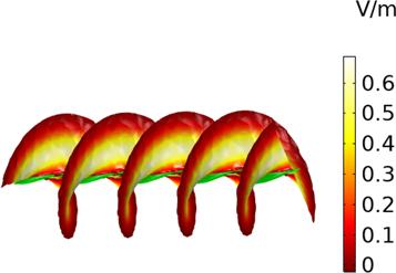
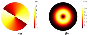
OAM beam also is called as vortex beam, it has a unique helical phase front of exp(ilφ) (i denotes the imaginary component, l is the topological charge and theoretically it can be any integer, φ is the azimuth), which means the phase front will change 2 πl when vortex beam rotates around the axial center for one cycle [8]. Laguerre–Gaussian beam is a kind of common OAM beam. Because vortex beam has spiral structure as shown in figure 4, the phase of its central point is uncertain. Therefore, a phase singularity that looks like a dark spot appears and the intensity distribution of vortex beam in the shape of a hollow circle. Figure 5 indicates phase profile and the electric field intensity profile of Laguerre–Gaussian beam, obtained by FEM when the topological charge l=2. It is obvious that the intensity is 0 at the phase singularity. Different kinds of OAM beams carry different information, and each photon of the beam carries lh OAM (h is the Planck constant divided by 2π). That is, the vortex beam can theoretically carry countless OAM when the topological charge l is infinite and the more OAM modes supported by the fiber, the larger capacity of the communication system is. Therefore, this technology greatly improves the communication capacity.Figure 4.
 New window|Download| PPT slide
Figure 4.Schematic diagram of vortex beam.
Figure 5.
 New window|Download| PPT slide
Figure 5.The vortex beam when the topological charge l=2 (a) phase profile; (b) electric field intensity profile.
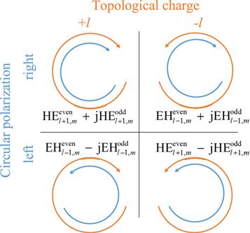
There are eigenmodes including HE mode, EH mode, TE mode and TM mode in optical communication. OAM modes are linear combinations of the even and odd mode, the even mode is obtained after π/2 phase differences of odd mode. The calculation of the number of OAM modes is performed through equations (
Figure 6.
 New window|Download| PPT slide
Figure 6.Schematic diagram of four OAM modes with the same topological charge.
The excitation approach of OAM modes has been already studied by the published papers. For example, in 2010, M Uchida et al [36] have achieved the excitation of OAM modes through spiral-like linear phase plates, which could be used to produced electron beams with topological charge of higher orders (∣l>2∣) by increasing or designing the step height of the phase plate. In 2011, A M Yao et al [37] obtained many OAM modes by the way of computer generation of holograms and spatial light modulators. In 2013, N Bozinovic et al [38] has reported the OAM modes in fiber can be excited by free-space OAM beams, free-space coupling was optimized when the beam profile and fiber annular core dimensions are matched; light that does not come through the annular core was lost. In 2014, C Brunet et al [15] have reported the generation of a perfect OAM beam is divided into two stages: the first controls the external beam width, while the second converts the Gaussian beam to an OAM beam with a tunable ring diameter. They confirmed excitation of both positive and negative order OAM modes, in both right- and left- circular polarization, confirming that a total of 36 information bearing modes, with topological charges from 0 to 9, are supported by that fiber. In 2018, M Seghilani et al [39] have shown a compact all fiber OAM generator/converter based on a PCF sliced on an OAM supporting fiber.
There are two kinds of methods can be used for exciting such many OAM modes after conducting a systematic search of the existing databases. One is the experimental setup in [15] for coupling of a perfect OAM beam with different topological charges into annular core fiber can excite a number of OAM modes, the number of generated and transmitted OAM through optical fiber decided by the number of supported OAM modes by the fiber. The 84 OAM modes supported by the proposed PCF can be excited and transmitted through the mentioned experimental setup. And the other is the compact all fiber OAM generator/converter in [39], which showed the possibility of tunable OAM excitation by changing the length of the PCF. Alternatively, high order OAM modes can be excited by cascading several PCF units. Tunable OAM generation with an on-demand electrically controlled charge can be achieved using the proposed OAM generator in that paper. To this purpose, one needs to cascade several units, and place after each one a 1×2 optical switch, with one output connected to the following OAM generator and the second one connected to a fan-in. However, it is easy to increase the length of the fiber or cascade several PCF units. Hence, the OAM modes supported by the proposed PCF also can be excited through this method.
Therefore, 84 OAM modes supported by the proposed PCF can be easily excited and transmitted through the mentioned ways.
The eigenmodes of the proposed PCF can be obtained through the FEM, then OAM modes supported by the PCF can be obtained through equations (
Figure 7.
 New window|Download| PPT slide
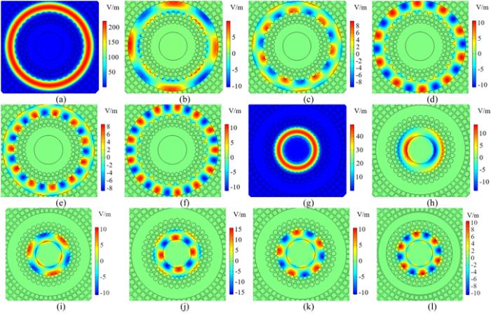
Figure 7.The intensity of the electric field: (a), (g) TE0,1 mode in the outer ring and inner ring; (b)–(f) z component of electric field intensity of HE4,1 mode, EH7,1 mode, HE10,1 mode, EH11,1 mode and HE13,1 mode in the outer ring; (h)–(l) z component of electric field intensity of EH1,1 mode, HE3,1 mode, EH4,1 mode, HE5,1 mode and HE6,1 mode in the inner ring.
Figure 8.
 New window|Download| PPT slide
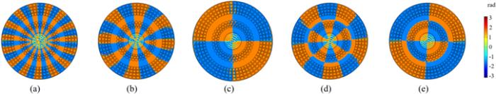
Figure 8.Phase profile of some typical eigenmodes (a) HE16,1 in the outer ring; (b) HE9,1 in the outer ring; (c) EH3,1 in the outer ring; (d) HE6,1 in the inner ring; (e) EH3,1 in the inner ring.
Figure 9.
 New window|Download| PPT slide
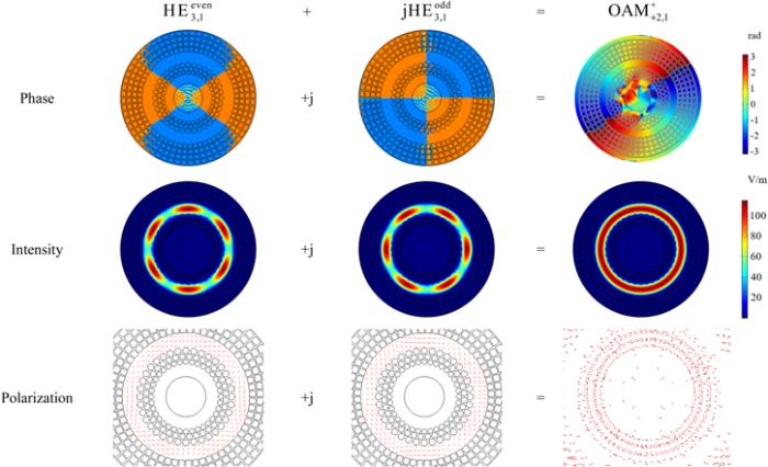
Figure 9.Generation processes of ${{\rm{OAM}}}_{+{\rm{2}},{\rm{1}}}^{+}.$
Thus, OAM modes supported by the proposed PCF can be obtained through the same way and they are given as following (${{\rm{OAM}}}_{\pm l,1}^{\pm }({\rm{o}})$ denotes the OAM mode supported by the outer ring, ${{\rm{OAM}}}_{\pm l,1}^{\pm }({\rm{i}})$ denotes the OAM mode supported by the inner ring):
It can be seen from above that there are 2 OAM modes when l=1, 4 OAM modes when mode with the same topological charge except l=1. Therefore, the proposed PCF supports 84 OAM modes when m=1.
3.2. Effective refractive index and the difference of effective refractive index
The effective refractive index of all modes in the two rings as a function of wavelength is shown in figure 10. It can be seen that the effective refractive index decreased by increasing wavelength, and the effect of wavelength on higher order mode is less than that of lower order mode. Additionally, effective refractive index of higher order mode is larger than that of lower order mode when wavelength takes a fixed value. The flattened effective refraction index indicates gently dispersion, because dispersion is evaluated by the differences of effective refractive index. It is shown in later that the lower order mode shows relatively flattened dispersion.Figure 10.
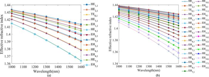 New window|Download| PPT slide
Figure 10.The relationship between effective refractive index and wavelength (a) the inner ring; (b) the outer ring.
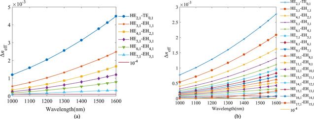
In order to effectively avoid adjacent modes coupling into LP mode, the difference of effective refractive index between adjacent modes must be above 10−4 [28]. The difference of the refractive index can be evaluated through equation (
The difference of effective refractive index between adjacent modes supported by the designed PCF is shown in figure 11. It can be seen that all of the values are higher than 10−4 and conform to the requirements of the transmission for OAM mode, although the difference of effective refractive index of higher order modes is lower than that of lower order modes. Therefore, the proposed PCF is conducive to reducing the coupling between OAM modes, ensuring better quality of OAM modes and facilitating accurate transmission of information in optical fiber communication [24, 28].
Figure 11.
 New window|Download| PPT slide
Figure 11.The differences of effective refractive index of different modes with respect to wavelength (a) the inner ring; (b) the outer ring.
3.3. Isolation parameter
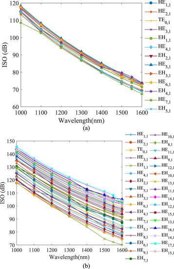
There are two kinds of crosstalk for dual-guided PCF: inter-mode crosstalk and inter-core crosstalk. Inter-mode crosstalk relies on the difference of effective refractive index between adjacent modes. By increasing the difference of effective refractive index, the inter-mode crosstalk will reduce. Besides, the inter-core crosstalk between the inner ring and outer ring is expressed by ISO, which is used to evaluate the crosstalk of power between channels [40]. ISO(o→i) denotes power leaking from the outer ring to the inner ring, and ISO(i→o) denotes power leaking from the inner ring to the outer ring. The ISO can be obtained by equations (Figure 12 indicates ISO of different eigenmodes varies with the wavelength. Here, with the increase of wavelength, ISO of different eigenmodes in the inner ring and outer ring decreases. Besides, all values of ISO are greater than 70 dB and the maximum value is up to 145 dB, which is 30 dB higher than the existing PCF [23]. Therefore, crosstalk between different regions guiding modes can be ignored and these two guided regions can be considered as a sharply independent channel with little power interaction. The proposed PCF with high ISO provides high feasibility for high-capacity optical fiber communication systems.
Figure 12.
 New window|Download| PPT slide
Figure 12.The relationship between ISO and wavelength (a) the inner ring; (b) the outer ring.
3.4. Mode purity
Mode purity represents the quality of OAM mode, which is a parameter must be discussed and analyzed in mode transmission. This is because encoding and multiplexing of OAM mode are performed successfully only when OAM mode has high quality. The mode purity (η) is quantitatively measured through equation (Figure 13.
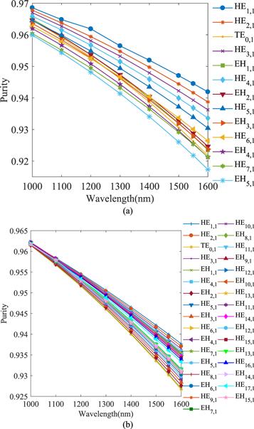 New window|Download| PPT slide
Figure 13.The relationship between the mode purity and wavelength (a) the inner ring; (b) the outer ring.
3.5. Dispersion properties
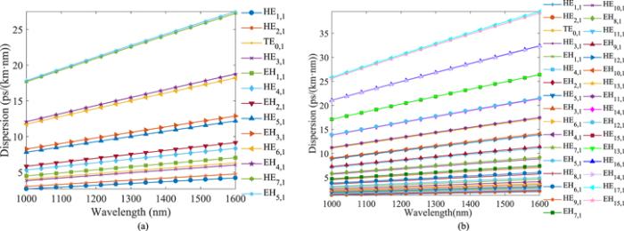
Dispersion is one of the most important parameters in optical waveguides, which has a great impact on the performance of fiber. It causes the broadening of optical pulses and restricts transmission rate. The value of dispersion can be calculated by equation (The relationship between dispersion and wavelength is shown in figure 14. The dispersion of higher order mode increases obviously with increasing wavelength. But the dispersion of lower order mode increases slowly with increasing wavelength, the trend is relatively gentle. This is because the effective refractive index of lower order mode changes flatly with increasing wavelength (as shown in figure 10). The dispersion of EH mode is larger than that of HE mode with the identical topological charge. This is because the effective refractive index of EH mode is lower than that of HE mode (as shown in figure 10) [22]. In addition, when the order of mode is higher, the dispersion is larger, so lower order mode is more stable in fiber transmission. As can be seen from figure 14, the dispersion variation of all modes in the inner ring is less than 27.5 ps·km−1·nm−1 and the dispersion variation of each mode is less than 9.7 ps·km−1·nm−1, the lowest dispersion variation is 1.5 ps·km−1·nm−1 of HE1,1 mode. Additionally, in the outer ring, the dispersion variation of all modes is less than 39.5 ps·km−1·nm−1, the dispersion variation of each mode is less than 13.7 ps·km−1·nm−1, and the lowest dispersion variation is 0.7 ps·km−1·nm−1 of HE1,1 mode. At the wavelength of 1550 nm, the lowest value of dispersion is 2 ps·km−1·nm−1 which is obtained for HE1,1 mode in the outer ring. However, in the PCF with circular air holes [41], the lowest dispersion variation is 46.38 ps·km−1·nm−1, the lowest value of dispersion is about 70 ps·km−1·nm−1 at 1550 nm; ring-core PCF [42] has the lowest dispersion variation of 60 ps·km−1·nm−1; spiral PCF structure [21] has the lowest dispersion variation of 4.4 ps·km−1·nm−1, the lowest value of dispersion is about 80 ps·km−1·nm−1 at 1550 nm; PCF with chain shaped air holes [24] has the lowest dispersion variation of 3.9 ps·km−1·nm−1, the lowest value of dispersion is about 50 ps·km−1·nm−1 at 1550 nm; ring PCF [16] has the lowest dispersion variation of 36.9 ps·km−1·nm−1, the lowest value of dispersion is about 50 ps·km−1·nm−1 at 1550 nm. It can be seen that dispersion of the proposed PCF is lower and flatter compared with existing PCFs. That is, it is a kind of PCF with quite low and flattened dispersion. In addition, PCF with low and flattened dispersion has more advantages in the accurate transmission of data, so the proposed PCF is a better choice for data transmission in optical fiber.
Figure 14.
 New window|Download| PPT slide
Figure 14.The relationship between the dispersion and wavelength (a) the inner ring; (b) the outer ring.
3.6. Confinement loss
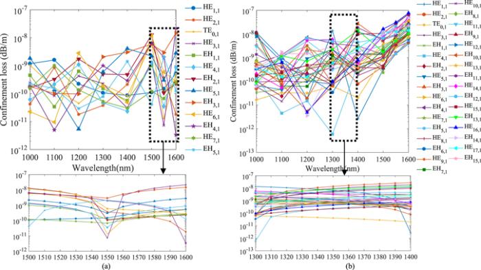
Confinement loss is considered to be a key optical parameter. It can be figured out by the imaginary component of the refractive index, as shown in equation (The change of confinement loss with wavelength is shown in figure 15. Although the variability of the confinement loss does not show significant regularity, the overall trend is ascending. This is mainly due to a higher probability of energy leaking into the cladding at larger wavelength. The reason for the fluctuation of the confinement loss is that the step size of wavelength is as large as 100 nm. The subgraph of figure 15(a) depicts the confinement loss of different OAM modes in the inner ring when the wavelength ranges from 1500 to 1600 nm with a step size of 10 nm. The subgraph of figure 15(b) depicts the confinement loss of different OAM modes in the outer ring when the wavelength ranges from 1300 to 1400 nm with a step size of 10 nm. It can be seen the confinement loss increases gently with wavelength when a smaller step size is adopted. As shown in figure 15, the highest confinement loss is only in the order of 10−8 dB m−1 when wavelength ranges from 1000 to 1600 nm. The lowest confinement loss in the inner ring is 4.5×10⁻¹² dB m−1 of EH4,1 mode at 1100 nm, the lowest confinement loss in the outer ring is 5×10⁻¹³ dB m−1 of EH13,1 mode at 1300 nm. It is 4–6 orders of magnitude lower than existing PCFs [24, 40–42]. At the common wavelength of 1550 nm, the lowest confinement loss is only 7.4×10⁻¹² dB m−1, which is 2–4 orders of magnitude lower than existing PCFs [21, 22, 26]. It is well known that lower confinement loss is more beneficial to the long-distance transmission of OAM mode. Therefore, the proposed PCF would be a strong candidate for long-distance and high-capacity optical fiber communication.
Figure 15.
 New window|Download| PPT slide
Figure 15.The relationship between wavelength and confinement loss (a) the inner ring; (b) the outer ring.
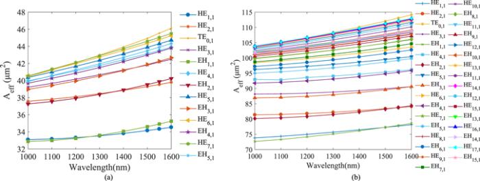
3.7. Effective mode area
The effective mode area of optical fiber is also a crucial parameter, which has a significant impact on the NA and nonlinearity. The effective mode area is characterized by Aeff and expressed by the equation (Figure 16.
 New window|Download| PPT slide
Figure 16.The relationship between wavelength and effective mode area (a) the inner ring; (b) the outer ring.
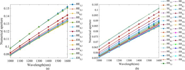
3.8. Numerical aperture
The total optical power is defined as NA. When the value of optical power increases then it has various applications in the optical field. Depth of field gained by decreasing values. NA can be obtained by equation (It can be seen from equation (
Figure 17.
 New window|Download| PPT slide
Figure 17.The relationship between wavelength and numerical aperture (a) the inner ring; (b) the outer ring.
3.9. Nonlinearity
The nonlinear effect in MDM is important. Nonlinearity is normally characterized by nonlinear coefficient. In addition, nonlinearity coefficient plays a vital role in the improvement of laser technology, which is a significant parameter of mode transmission. The lower the nonlinearity coefficient is, the smaller the nonlinear effect is, and the better the transmission performance of optical fiber communication system will be. Nonlinearity is denoted by γ and defined by equation (It can be seen from equation (
Figure 18.
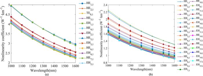 New window|Download| PPT slide
Figure 18.The relationship between wavelength and nonlinearity coefficient (a) the inner ring; (b) the outer ring.
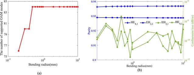
3.10. Bending effects
The bending loss is crucial for the fiber optics communication. The influence of bending on the number of supported OAM modes, confinement loss, and mode purity of the proposed PCF are analyzed when λ=1550 nm. Figure 19(a) indicates that the number of supported OAM modes decreases to 76 when the bending radius is lower than 0.2 mm, and it could maintain 84 modes until the bending radius up to 0.5 mm. Figure 19(b) shows the purity and confinement loss of eigenmodes vary with bending radius, these eigenmodes combine to OAM3,1 mode. In figure 19(b), the blue lines indicate mode purity of HE4,1 mode and EH2,1 mode in the inner ring, the green lines indicate confinement loss of HE4,1 mode and EH2,1 mode in the inner ring. As the bending radius increases, the mode quality of both HE4,1 and EH2,1 mode maintains their properties up to 93.6% and 92.8%, respectively. The confinement loss of both HE4,1 and EH2,1 mode is lower than 10−8 dB m−1 and 10−9 dB m−1, respectively. However, in the straight fiber, the mode purity and confinement loss of HE4,1 mode in the inner ring is 93.7% and 3.52×10⁻¹¹ dB m−1, the mode purity and confinement loss of EH2,1 mode in the inner ring is 92.9% and 1.06×10⁻¹¹ dB m−1, respectively. It can be seen that the bending effect on the proposed PCF is slight. The properties of other modes are analyzed through numerical analysis and the results show that they have the same properties. Therefore, the proposed PCF could maintain 84 modes and their optical properties in any bending environment with a bending radius not less than 0.5 mm.Figure 19.
 New window|Download| PPT slide
Figure 19.(a) The number of supported OAM modes depending on bending radius; (b) the change of the mode quality and confinement loss with bending radius.
3.11. Comparison
Table 1 shows comparison of the PCF proposed in this paper with existing PCFs about some crucial properties, such as the number of supported OAM modes, lowest dispersion variation, lowest confinement loss, lowest nonlinearity coefficient and ISO. It can be seen that the proposed PCF supports as many as 84 OAM modes, which is the most comparing with the existing PCFs in table 1. At the same time, the proposed PCF has higher mode purity for all OAM modes than the existing PCFs, which are above 91.7% and ensure better coding and multiplexing of optical signals in optical fiber communication system. The lowest dispersion variation and the lowest confinement loss are as low as 0.7 ps·km−1·nm−1 and 5×10⁻¹³ dB m−1 respectively, which are obviously lower than all the values listed in the table and ensure the long-distance and accurate transmission of optical fiber communication. Although the lowest nonlinearity coefficient of the proposed PCF is not the lowest in the table, it is so low that the proposed PCF is more beneficial to MDM. In addition, the proposed PCF has higher ISO than the existing PCFs, which are greater than 70 dB and the maximum value is up to 145 dB. Thus, the crosstalk between different regions guiding modes can be ignored. It’s worth noting that all properties are studied in this paper has been improved. The details are as follows: the lowest dispersion variation, the lowest confinement loss, the lowest nonlinearity coefficient and ISO is reduced to 3/200–37/100, reduced by over 1 orders of magnitude, reduced to 9/25–43/50, improved by about 33–59 dB respectively.Table 1.
Table 1.Comparison of the proposed PCF with existing PCFs about some of the crucial properties.
| References | Operating band | Supported OAM modes | OAM purity | Lowest dispersion variation | Lowest confinement loss | Lowest nonlinearity coefficient | ISO |
|---|---|---|---|---|---|---|---|
| nm | — | — | ps·km−1·nm−1 | dB m−1 | W−1·km−1 | dB | |
| [16] | 600–2500 | 56 | >89% | 36.9 | 1.74×10⁻¹¹ | 0.5 | — |
| [21] | 1350–1950 | 14 | — | 4.4 | 5.08×10⁻³ | 2.78 | — |
| [23] | 1400–1700 | 56 | >80% | — | 10−8 | — | 20–112 |
| [25] | 800–2000 | 38 | >85% | 4.75 | 6.87×10⁻¹⁰ | 1.04 | — |
| [41] | 1250–2000 | 14 | — | 46.38 | 10−12 | 2.5 | — |
| [46] | 1520–1580 | 30 | — | 1.88 | 10−12 | 1.92 | 15–86 |
| [47] | 1000–2500 | 80 | — | — | 10−6 | 1.26×10⁵ | — |
| [48] | 1000–2000 | 38 | — | 0.916 | 1.534×10⁻⁹ | 0.997 | — |
| Proposed | 1000–1600 | 84 | >91.7% | 0.7 | 5×10⁻¹³ | 0.9 | 67–145 |
New window|CSV
According to the discussion of sections
4. Conclusion
In this paper, a novel PCF with circular air holes and rectangular air holes is proposed. The proposed PCF is investigated through the FEM. Results show the proposed PCF has excellent properties, such as supporting a large number OAM modes, high mode quality and ISO, low and flattened dispersion. In a bandwidth of 600 nm (1000–1600 nm), the proposed PCF supports up to 84 OAM modes; all the differences of effective refractive index are above 10−4; the purity of all modes is greater than 91.7%; the ISO can be up to 145 dB, and the crosstalk can be ignored; the lowest dispersion variation is only 0.7 (ps·km−1·nm−1) of HE1,1 mode in the outer ring, and the overall dispersion is relatively flattened; EH13,1 mode in the outer ring obtains its lowest confinement loss at 1300 nm, which is 5×10⁻¹³ dB m−1 and reduced by 4–6 orders of magnitude; TE0,1 mode obtains its maximum effective mode area and lowest nonlinear coefficient at 1600 nm, which is 114 μm2 and 0.9 W−1·km−1. Therefore, the proposed PCF will be easier to realize the multiplexing of OAM mode, and it has a better prospect in optical fiber communication system with high performance, large capacity, coding and multiplexing.Acknowledgments
This work was supported by the Fundamental Research Funds for the Central Universities (2020YJ005, 2021MS072, 2019MS085), the Natural Science Foundation of Hebei Province (E2019502177, E2020502010) and the National Natural Science Foundation of China (51607066, 61775057).Reference By original order
By published year
By cited within times
By Impact factor
DOI:10.3788/gzxb20215002.0206001 [Cited within: 1]
DOI:10.3964/j.issn.1000-0593(2020)03-0842-07
DOI:10.1364/OE.392127 [Cited within: 1]
DOI:10.1109/JLT.2009.2039464 [Cited within: 1]
DOI:10.1109/JLT.2016.2524546 [Cited within: 1]
DOI:10.1088/0253-6102/70/4/384 [Cited within: 1]
DOI:10.1088/0253-6102/66/5/501 [Cited within: 1]
DOI:10.1038/nphoton.2012.138 [Cited within: 2]
DOI:10.1364/OE.24.008310 [Cited within: 1]
DOI:10.1364/OPTICA.1.000165
DOI:10.1103/PhysRevLett.110.143903 [Cited within: 1]
DOI:10.1109/JPHOT.2012.2192474 [Cited within: 2]
DOI:10.3390/cryst7100286
DOI:10.1109/JPHOT.2016.2545645 [Cited within: 1]
DOI:10.1364/OE.22.026117 [Cited within: 5]
DOI:10.1016/j.optcom.2020.126003 [Cited within: 4]
DOI:10.1016/j.ijleo.2020.164209 [Cited within: 1]
DOI:10.1126/science.1223824 [Cited within: 1]
DOI:10.1364/OL.41.003591 [Cited within: 1]
DOI:10.1016/j.optcom.2017.03.075 [Cited within: 1]
DOI:10.1016/j.ijleo.2018.05.055 [Cited within: 4]
DOI:10.1016/j.ijleo.2018.01.015 [Cited within: 6]
DOI:10.1016/j.yofte.2020.102213 [Cited within: 3]
DOI:10.1007/s11082-019-2125-0 [Cited within: 8]
DOI:10.1016/j.optcom.2020.125731 [Cited within: 3]
DOI:10.1007/s11082-020-02447-w [Cited within: 4]
DOI:10.1016/j.aej.2020.09.004 [Cited within: 1]
DOI:10.1364/OL.34.002525 [Cited within: 3]
DOI:10.1364/OE.20.029751 [Cited within: 1]
DOI:10.1364/OPEX.12.003500 [Cited within: 1]
DOI:10.1364/OPEX.12.000859 [Cited within: 1]
DOI:10.1016/j.infrared.2014.08.007 [Cited within: 1]
DOI:10.1016/j.yofte.2015.08.010 [Cited within: 1]
DOI:10.1364/OE.10.001520 [Cited within: 1]
DOI:10.1016/j.optcom.2019.01.007 [Cited within: 1]
DOI:10.1038/nature08904 [Cited within: 1]
DOI:10.1364/AOP.3.000161 [Cited within: 1]
DOI:10.1126/science.1237861 [Cited within: 1]
DOI:10.1109/LPT.2018.2789840 [Cited within: 2]
DOI:10.1016/j.optcom.2020.126192 [Cited within: 2]
DOI:10.1109/LPT.2016.2551325 [Cited within: 4]
DOI:10.1364/OL.37.001889 [Cited within: 2]
DOI:10.1016/j.ijleo.2016.04.137 [Cited within: 1]
DOI:10.1016/j.ijleo.2011.02.003 [Cited within: 1]
DOI:10.1109/JSEN.2017.2775642 [Cited within: 1]
DOI:10.1007/s12596-018-0487-5 [Cited within: 1]
DOI:10.1117/1.OE.58.8.086108 [Cited within: 1]
DOI:10.1007/s00340-020-07497-2 [Cited within: 1]
