柳懿,唐炜豪,嵇斗
(海军工程大学 电气工程学院,武汉 430033)
摘要:
为了进一步分析影响舰船电场的不同因素,提高舰艇水下静电场仿真分析中电偶极子建模方法的准确性,研究产生舰艇水下腐蚀静电场的腐蚀电化学原理和特性,从腐蚀电流密度的角度推导船体-螺旋桨电偶腐蚀电流表达式,并利用镜像法求解出了空气海水二层模型下水平和垂直电偶极子电场解析式。建立基于舰艇腐蚀电流电偶极子的电场解析模型,在此基础上利用数值仿真对一中型舰艇水下50 m测线上的电场进行分析。结果表明:在设定变化范围内,船体腐蚀电位、螺旋桨腐蚀电位、船体浸水面积、螺旋桨浸水面积、海水温度、海水电导率对舰艇水下腐蚀静电场的影响程度分别约为29%、23%、53%、82%、30%和67%。仿真结果和电场解析模型可以为进一步研究舰艇水下腐蚀静电场特征及防护方法提供有力的理论支撑。
关键词: 腐蚀静电场 腐蚀电流密度 电偶极子 腐蚀电位 海水电导率
DOI:10.11918/202205023
分类号:TN95
文献标识码:A
基金项目:国家自然科学基金(41476153)
Calculation of electrostatic field of underwater corrosion of ship and simulation analysis of influencing factors
LIU Yi,TANG Weihao,JI Dou
(College of Electrical Engineering, Naval University of Engineering, Wuhan 430033, China)
Abstract:
In order to further analyze the different factors affecting ship electric field and improve the accuracy of electric dipole modeling method in ship underwater electrostatic field simulation analysis. The corrosion electrochemical principle and characteristics of underwater corrosion electrostatic field are studied. The expression of galvanic corrosion current of ship-propeller is derived from the angle of corrosion current density. The analytical expressions of horizontal and vertical electric dipole electric field are solved by mirror image method under air-seawater two-layer model. The analytical model of the electric field based on the corrosion current dipole of the ship is established. On this basis, the electric field on the underwater 50 m line of a medium-sized ship is analyzed by numerical simulation. The results show that within the set range of variation, the influence degree of the corrosion potential of the hull and propeller, the immersion area of the hull and propeller, the seawater temperature and the seawater conductivity on the underwater corrosion electrostatic field of the ship are about 29%, 23%, 53%, 82%, 30% and 67%, respectively. The simulation results and the analytical model of the electric field can provide strong theoretical support for the further study of the electrostatic field characteristics and protection methods of underwater corrosion of ships.
Key words: corrosion electrostatic field corrosion current density electric dipole corrosion potential seawater conductivity
柳懿, 唐炜豪, 嵇斗. 舰艇水下腐蚀静电场计算及影响因素仿真分析[J]. 哈尔滨工业大学学报, 2024, 56(7): 154-161. DOI: 10.11918/202205023.

LIU Yi, TANG Weihao, JI Dou. Calculation of electrostatic field of underwater corrosion of ship and simulation analysis of influencing factors[J]. Journal of Harbin Institute of Technology, 2024, 56(7): 154-161. DOI: 10.11918/202205023.

基金项目 国家自然科学基金(41476153) 作者简介 柳懿(1981—),男,博士,副教授 通信作者 柳懿,timjoan@163.com 文章历史 收稿日期: 2022-05-08
Abstract Full text Figures/Tables PDF
舰艇水下腐蚀静电场计算及影响因素仿真分析
柳懿

 , 唐炜豪, 嵇斗
 海军工程大学 电气工程学院,武汉 430033
收稿日期: 2022-05-08; 录用日期: 2022-06-20; 网络首发日期: 2024-05-22
基金项目: 国家自然科学基金(41476153)
作者简介: 柳懿(1981—),男,博士,副教授
通信作者: 柳懿,timjoan@163.com
摘要: 为了进一步分析影响舰船电场的不同因素,提高舰艇水下静电场仿真分析中电偶极子建模方法的准确性, 研究产生舰艇水下腐蚀静电场的腐蚀电化学原理和特性,从腐蚀电流密度的角度推导船体-螺旋桨电偶腐蚀电流表达式,并利用镜像法求解出了空气-海水二层模型下水平和垂直电偶极子电场解析式。建立基于舰艇腐蚀电流电偶极子的电场解析模型,在此基础上利用数值仿真对一中型舰艇水下50 m测线上的电场进行分析。结果表明:在设定变化范围内,船体腐蚀电位、螺旋桨腐蚀电位、船体浸水面积、螺旋桨浸水面积、海水温度、海水电导率对舰艇水下腐蚀静电场的影响程度分别约为29%、23%、53%、82%、30%和67%。仿真结果和电场解析模型可以为进一步研究舰艇水下腐蚀静电场特征及防护方法提供有力的理论支撑。
关键词: 腐蚀静电场 腐蚀电流密度 电偶极子 腐蚀电位 海水电导率
Calculation of electrostatic field of underwater corrosion of ship and simulation analysis of influencing factors
LIU Yi

 , TANG Weihao, JI Dou
 College of Electrical Engineering, Naval University of Engineering, Wuhan 430033, China
Abstract: In order to further analyze the different factors affecting ship electric field and improve the accuracy of electric dipole modeling method in ship underwater electrostatic field simulation analysis. The corrosion electrochemical principle and characteristics of underwater corrosion electrostatic field are studied. The expression of galvanic corrosion current of ship-propeller is derived from the angle of corrosion current density. The analytical expressions of horizontal and vertical electric dipole electric field are solved by mirror image method under air-seawater two-layer model. The analytical model of the electric field based on the corrosion current dipole of the ship is established. On this basis, the electric field on the underwater 50 m line of a medium-sized ship is analyzed by numerical simulation. The results show that within the set range of variation, the influence degree of the corrosion potential of the hull and propeller, the immersion area of the hull and propeller, the seawater temperature and the seawater conductivity on the underwater corrosion electrostatic field of the ship are about 29%, 23%, 53%, 82%, 30% and 67%, respectively. The simulation results and the analytical model of the electric field can provide strong theoretical support for the further study of the electrostatic field characteristics and protection methods of underwater corrosion of ships.
Keywords: corrosion electrostatic field corrosion current density electric dipole corrosion potential seawater conductivity
根据新世纪新阶段海军构建的作战力量体系和应具备的作战能力要求,舰艇需要在近海甚至远海执行多种作战任务,这种需求对舰艇装备的发展提出了各种新要求[1]。舰艇的各个部件是由各种不同金属材料建造, 常见的状态是: 制造船壳的材料通常为各种型号的钢材,制造螺旋桨的材料通常为镍铝青铜,制造球鼻艏的材料为钛合金、玻璃钢、不锈钢等[2-3]。不同金属在海水中具有不同的化学性质,会形成不同的稳定电极电位。舰艇在海洋服役期间,在海水环境中,舰艇铜制的螺旋桨和钢制的船壳稳定地维持一定的电位差,同时在舰艇内部,船壳和螺旋桨通过无源轴接地装置处于电气导通状态[4-6]。
这样一来,舰艇在海水中就可以被理解成为一个结构复杂的宏观腐蚀电池,腐蚀电流从船壳通过海水流入到螺旋桨,再经过大轴、各种轴承、密封、机械线路及无源轴接地装置回到船壳,形成一个完整的腐蚀电流回路。此腐蚀电流在海水中以固定的方向稳定流动,建立具有一定电场强度的恒定电场。根据最早引进的俄罗斯资料以及行业内多年的习惯,将此由腐蚀电流产生的恒定电场称为舰艇水下腐蚀静电场[7-8]。
电偶极子建模是进行舰艇水下静电场仿真分析的常用方法[9-10],但是该方法中的电偶电流是根据实际经验设置的,准确度不高,且不能从理论上分析电化学参数对腐蚀静电场的影响。为了提高舰艇水下静电场仿真分析中电偶极子建模方法的准确性,本文从电化学原理中腐蚀电流密度的角度建立了基于舰艇腐蚀电流电偶极子的电场解析模型,准确地分析了不同参数对腐蚀静电场的影响。
1 舰艇水下腐蚀电流的计算分析舰艇通常由不同金属材料制造并一直浸泡在海水环境中,必然会产生电化学腐蚀。由于不同金属内部正离子和电子的大小与排列方式不同,在海水环境中形成的双电层电荷密度就会不同,导致不同金属的电极电位不同[11]。常见舰艇制造用金属电极电位[12-13]见表 1。
表 1
1 921A(10CrNi3MoV) -690
2 945钢 -675
3 20号钢 -755
4 304不锈钢(O22Cr19Ni10) -46
5 青铜(ZCuSn10Zn2)(10-2锡青铜) -176
6 青铜(ZCuAl8Mn13Fe3Ni2) -186
7 B10(铜镍合金) -117
表 1 常见舰艇制造用金属电极电位(相对于氢参比电极) Tab. 1 Electrode potential (relative to hydrogen reference electrode) for major naval materials
在舰艇腐蚀体系中,铜制螺旋桨电位高为阴极,而钢制船体电位低则为阳极,这两种金属在海水中会形成电位差。回路中将产生腐蚀电流,舰艇内部腐蚀电流从电位相对较高的螺旋桨流向电位相对较低的船体;在海水中腐蚀电流则借助于离子由船体流入到螺旋桨。产生腐蚀电流后,船体上电子通过内部回路转移到螺旋桨,导致船体上双电层中电子密度降低,则船体电位变正;而螺旋桨获得电子,螺旋桨上双电层中电子密度升高,螺旋桨电位变负[14]。这样船体和螺旋桨之间电位差ΔU会慢慢减小,回路中腐蚀电流也相应慢慢减小。腐蚀原电池反应过程中,阴极和阳极间电位差不断减小,使得回路腐蚀电流减小的现象称作极化。极化现象使得电化学腐蚀程度得到减缓。但是由于海水中存在有大量的氧和氢的离子,氧和氢的离子在阴极铜制螺旋桨上会进行“去极化”反应。“去极化”反应不断地消耗从阳极铁板流入阴极铜板的电子,这样就阻碍了阴极电位进一步变负和阳极电位进一步变正,使得腐蚀原电池两电极间总维持有一定的电位差ΔU。
显然,由舰艇不同材料相互接触而产生的腐蚀电场在舰艇静止时也存在,它基本上是一个静电场。这种船体和螺旋桨形成的结构复杂宏观腐蚀电池现象,是舰艇水下腐蚀静电场最主要起源之一。材料和去极化的强弱决定了宏观腐蚀电池的电压,也就决定了舰艇水下腐蚀静电场的强弱[15-16]。
但在舰艇航行时,由于海水在舰艇周围快速流动,使得在与船体和螺旋桨相接触区域不断补充新鲜的海水,保证海水中氧气含量充足。因而加快了“去极化”的进程,使船体和螺旋桨之间的电位差稳定值有所增加,即舰艇水下腐蚀静电场会相应增强。此外,海水温度的升高会显著加速微粒传导速率,促进电化学反应速率,从而导致船壳腐蚀加速[17]。
1.1 独立金属腐蚀电流密度计算独立金属放置在海水溶液中,金属的电子导体相和导电溶液中的离子导体相相互接触,形成一个电极系统。在此电极系统中,金属表面同时在进行阳极反应和阴极反应。根据电化学动力学公式,如果金属的电极电位为零,则金属表面的阳极反应速度va0和阴极反应速度vk0分别为
$v_{\mathrm{a}}^{0}=k_{\mathrm{a}} c_{\mathrm{R}} \exp \left(-\frac{W_{\mathrm{a}}^{0}}{R T}\right)=K_{\mathrm{a}}^{0} c_{\mathrm{R}}$ (1)
$v_{\mathrm{k}}^{0}=k_{\mathrm{k}} c_{\mathrm{o}} \exp \left(1-\frac{W_{\mathrm{k}}^{0}}{R T}\right)=K_{\mathrm{k}}^{0} c_{0}$ (2)
式中:ka和kk为指数前因子;cR和cO为还原态和氧化态物质的浓度;
根据电流密度i与电极反应速度v的关系i=nFv,可以由式(1)和式(2)得到阳极反应电流密度与阴极反应电流密度表达式:
$\overleftarrow{i}_{\mathrm{a}}^{0}=n F K_{\mathrm{a}}^{0} c_{\mathrm{R}}$ (3)
$\vec{i}_{\mathrm{k}}^{0}=n F K_{\mathrm{k}}^{0} c_{0}$ (4)
式中:
实际情况中,记金属的电极电位为E,金属的过电位为φ=E-Eeq,则金属阳极反应活化能Wa=Wa0-(1-α)nFφ,金属阴极反应活化能Wk=Wk0+αnFφ,其中,α为电荷传递系数,无量纲。此时,金属阳极反应和阴极反应电流密度表达式变化分别为
$\begin{gather*}\overleftarrow{i}_{\mathrm{a}}=n F k_{\mathrm{a}} c_{\mathrm{R}} \exp \left[-\frac{W_{\mathrm{a}}^{0}-(1-\alpha) n F \varphi}{R T}\right]= \\n F K_{\mathrm{a}}^{0} c_{\mathrm{R}} \exp \left[\frac{(1-\alpha) n F \varphi}{R T}\right] \end{gather*}$ (5)
$\begin{gather*}\vec{i}_{\mathrm{k}}=n F k_{\mathrm{k}} c_{0} \exp \left(-\frac{W_{\mathrm{k}}^{0}+\alpha n F \varphi}{R T}\right)= \\n F K_{\mathrm{k}}^{0} c_{0} \exp \left(-\frac{\alpha n F \varphi}{R T}\right)\end{gather*}$ (6)
式中
1.2 船体-螺旋桨电偶腐蚀的腐蚀电流计算当两种具有不同电极电位金属发生电接触时,金属表面电子转移速度比电化学反应速度快,在金属表面就会出现剩余电荷,导致金属电极电位发生偏离。当金属表面
船体金属在电化学腐蚀电偶中为阳极,设为MFe,螺旋桨金属在电化学腐蚀电偶中为阴极,设为MCu。假设两种金属在互相接触前,各自稳定腐蚀电位分别为φcorr, Fe和φcorr, Cu,腐蚀电流密度分别为ia, Fe和ik, Cu。对于舰艇船体-螺旋桨形成的腐蚀电流,作为阳极的船体表面表现为净阳极腐蚀电流密度
$\begin{gather*}i_{\mathrm{a}, \mathrm{Fe}}=\overleftarrow{i}_{\mathrm{a}, \mathrm{Fe}}-\vec{i}_{\mathrm{k}, \mathrm{Fe}}= \\n F K_{\mathrm{a}}^{0} c_{\mathrm{R}} \exp \left[\frac{(1-\alpha) n F \varphi_{\mathrm{corr}, \mathrm{Fe}}}{R T}\right]- \\n F K_{\mathrm{k}}^{0} c_{0} \exp \left(-\frac{\alpha n F \varphi_{\text {corr }, \mathrm{Fe}}}{R T}\right) \end{gather*}$ (7)
$\begin{gather*}i_{\mathrm{k}, \mathrm{Cu}}=\vec{i}_{\mathrm{k}, \mathrm{Cu}}-\overleftarrow{i}_{\mathrm{k}, \mathrm{Cu}}= \\n F K_{\mathrm{k}}^{0} c_{0} \exp \left(-\frac{\alpha n F \varphi_{\text {corr }, \mathrm{Cu}}}{R T}\right)- \\n F K_{\mathrm{a}}^{0} c_{\mathrm{R}} \exp \left[\frac{(1-\alpha) n F \varphi_{\text {corr }, \mathrm{Cu}}}{R T}\right] \end{gather*}$ (8)
不考虑浓差极化情况下,而且海水溶液的电阻比较小,船体内部电阻也很小,船体和螺旋桨通过大轴轴系结构短接后都极化到同一电位φg,可以得到船体作为阳极的极化电流密度为
$\begin{equation*}I_{\mathrm{Fe}}=i_{\mathrm{a}, \mathrm{Fe}}\left[\exp \left(\frac{\varphi_{\mathrm{g}}-\varphi_{\mathrm{corr}, \mathrm{Fe}}}{\beta_{\mathrm{a}, \mathrm{Fe}}}\right)-\exp \left(-\frac{\varphi_{\mathrm{g}}-\varphi_{\mathrm{corr}, \mathrm{Fe}}}{\beta_{\mathrm{c}, \mathrm{Fe}}}\right)\right] \end{equation*}$ (9)
对于螺旋桨来说,它是阴极极化,φg-φcorr, Cu < 0,因此极化电流是负值。所以本文使用| ICu|这个绝对值来表示螺旋桨极化到电位φg时的阴极极化电流密度,它应为
$\begin{equation*}\left|I_{\mathrm{Cu}}\right|=i_{\mathrm{k}, \mathrm{Cu}}\left[\exp \left(-\frac{\varphi_{\mathrm{g}}-\varphi_{\mathrm{corr}, \mathrm{Cu}}}{\beta_{\mathrm{c}, \mathrm{Cu}}}\right)-\exp \left(\frac{\varphi_{\mathrm{g}}-\varphi_{\mathrm{corr}, \mathrm{Cu}}}{\beta_{\mathrm{a}, \mathrm{Cu}}}\right)\right] \end{equation*}$ (10)
式(9)、(10)中βa, Fe, βc, Fe分别为MFe的阳极和阴极反应系数,βa, Cu, βc, Cu分别为MCu的阳极和阴极反应系数,无量纲。若船体在海水溶液中的浸水面积为AFe,螺旋桨在海水溶液中的浸水面积为ACu,这一腐蚀原电池的海水电路中的腐蚀电流ig
为
$\begin{equation*}i_{\mathrm{g}}=I_{\mathrm{Fe}} A_{\mathrm{Fe}}=\left|I_{\mathrm{Cu}}\right| A_{\mathrm{Cu}} \end{equation*}$ (11)
以上得到的腐蚀电流公式比较复杂,由于Fe-Cu电偶腐蚀属于强极化的范围,可以对以上公式进行一些简化。将船体看作是腐蚀原电池中纯阳极,在船体表面的阴极还原反应速度非常慢,不予考虑,认为船体只进行阳极溶解反应;将螺旋桨看作是腐蚀原电池中纯阴极,在螺旋桨表面的阳极溶解反应速度非常慢,不予考虑,认为螺旋桨只进行阴极还原反应。
在该情况下,
$\begin{align*}i_{\mathrm{g}}= & A_{\mathrm{Fe}} n F K_{\mathrm{a}}^{0} c_{\mathrm{R}} \exp \left[\frac{(1-\alpha) n F \boldsymbol{\varphi}_{\mathrm{corr}, \mathrm{Fe}}}{R T}\right] \exp \left(\frac{\varphi_{\mathrm{g}}-\varphi_{\mathrm{corr}, \mathrm{Fe}}}{\beta_{\mathrm{a}, \mathrm{Fe}}}\right)= \\& A_{\mathrm{Cu}} n F K_{\mathrm{k}}^{0} c_{0} \exp \left(-\frac{\alpha n F \varphi_{\mathrm{corr}, \mathrm{Cu}}}{R T}\right) \exp \left(-\frac{\varphi_{\mathrm{g}}-\varphi_{\mathrm{corr}, \mathrm{Cu}}}{\beta_{\mathrm{c}, \mathrm{Cu}}}\right) \end{align*}$ (12)
由上式可以解出:
$\varphi_{\mathrm{g}}=\frac{\beta_{\mathrm{c}, \mathrm{Cu}}}{\beta_{\mathrm{a}, \mathrm{Fe}}+\beta_{\mathrm{c}, \mathrm{Cu}}} \varphi_{\mathrm{corrFe}}+\frac{\beta_{\mathrm{a}, \mathrm{Fe}}}{\beta_{\mathrm{a}, \mathrm{Fe}}+\beta_{\mathrm{c}, \mathrm{Cu}}} \varphi_{\text {corr }, \mathrm{Cu}}+ \\ \frac{\beta_{\mathrm{a}, \mathrm{Fe}} \beta_{\mathrm{c}, \mathrm{Cu}}}{\beta_{\mathrm{a}, \mathrm{Fe}}+\beta_{\mathrm{c}, \mathrm{Cu}}} \ln \frac{A_{\mathrm{Cu}} n F K_{\mathrm{k}}^{0} c_{0} \exp \left(-\frac{\alpha n F \varphi_{\text {corr }, \mathrm{Cu}}}{R T}\right)}{A_{\mathrm{Fe}} n F K_{\mathrm{a}}^{0} c_{\mathrm{R}} \exp \left[\frac{(1-\alpha) n F \varphi_{\mathrm{corr}, \mathrm{Fe}}}{R T}\right]}$ (13)
$\ln i_{\mathrm{g}}=\frac{\varphi_{\text {corr }, \mathrm{Cu}}-\varphi_{\text {corr }, \mathrm{Fe}}}{\beta_{\mathrm{a}, \mathrm{Fe}}+\beta_{\mathrm{c}, \mathrm{Cu}}}+ \\ \frac{\beta_{\mathrm{a}, \mathrm{Fe}}}{\beta_{\mathrm{a}, \mathrm{Fe}}+\beta_{\mathrm{c}, \mathrm{Cu}}} \ln \left[A_{\mathrm{Fe}} n F K_{\mathrm{a}}^0 c_{\mathrm{R}} \exp \frac{(1-\alpha) n F \varphi_{\mathrm{corr}, \mathrm{Fe}}}{R T}\right]+ \\ \frac{\beta_{\mathrm{c}, \mathrm{Cu}}}{\beta_{\mathrm{a}, \mathrm{Fe}}+\beta_{\mathrm{c}, \mathrm{Cu}}} \ln \left[A_{\mathrm{Cu}} n F K_{\mathrm{k}}^0 c_0 \exp \left(-\frac{\alpha n F \varphi_{\text {corr }, \mathrm{Cu}}}{R T}\right)\right]$ (14)
即
$\begin{gather*}i_{\mathrm{g}}=\exp \frac{\varphi_{\mathrm{corr}, \mathrm{Cu}}-\varphi_{\text {corr }, \mathrm{Fe}}}{\beta_{\mathrm{a}, \mathrm{Fe}}+\beta_{\mathrm{c}, \mathrm{Cu}}}+ \\\frac{\beta_{\mathrm{a}, \mathrm{Fe}}}{\beta_{\mathrm{a}, \mathrm{Fe}}+\beta_{\mathrm{c}, \mathrm{Cu}}} A_{\mathrm{Fe}} n F K_{\mathrm{a}}^{0} c_{\mathrm{R}} \exp \frac{(1-\alpha) n F \varphi_{\mathrm{corr}, \mathrm{Fe}}}{R T}+ \\\frac{\beta_{\mathrm{c}, \mathrm{Cu}}}{\beta_{\mathrm{a}, \mathrm{Fe}}+\beta_{\mathrm{c}, \mathrm{Cu}}} A_{\mathrm{Cu}} n F K_{\mathrm{k}}^{0} c_{0} \exp \left(-\frac{\alpha n F \varphi_{\mathrm{corr}, \mathrm{Cu}}}{R T}\right) \end{gather*}$ (15)
2 基于舰艇水下腐蚀电流的水下腐蚀静电场计算分析研究舰艇水下腐蚀电流产生的水下腐蚀静电场时,可以使用静态电偶极子I·dl的概念进行等效计算。其中,I为腐蚀电流,l为船体和螺旋桨之间的等效电偶距离。I·dl作为一个向量,它可以分解为X、Y、Z三个方向向量的叠加[18-19]。假设舰艇的腐蚀状态是均匀的,则腐蚀电流关于舰艇左右对称。此时只需要将I·dl分解为X、Z两个方向。水平电偶极子Ix·dlx,方向指向X轴正向;垂直电偶极子Iz·dlz,方向指向Z轴正向。
舰艇一般航行在深海区域,此时将海水深度视为无穷远,这样就建立一个空气-海水两层模型。建立右旋笛卡尔直角坐标系O-XYZ,如图 1所示。其中X轴正方向为平面向右,Y轴正方向为垂直平面向外,Z轴正方向为平面向下。XY形成的平面为海平面,XY平面以下为海水,XY平面以上为空气。假设等效腐蚀电流的电偶极子坐标为(x0, y0, z0)。
Fig. 1
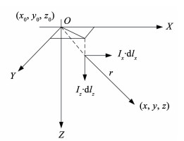 图 1 空气-海水二层模型 Fig. 1 Air-seawater model
 空气-海水两层模型中,空气的介电常数、磁导率、电导率分别为ε0, μ0, σ0;海水的介电常数、磁导率、电导率分别为ε1, μ1, σ1。有ε0=1,ε1=81, μ0=μ1=4π×10-7 H/m, σ0=0 S/m。分析计算电偶极子产生的水下静电场时,使用镜像法求解[20],使用此方法的原因是空气-海水二层模型满足同样的边界条件,采用镜像法求解后,只须将原点和镜像点的结果进行简单叠加,就可以简单解决存在介质界面的求解问题。以空气-海水分界面为镜时,海水中的电偶极子在空气中的镜像坐标为(x0, y0, -z0),上文描述的舰艇腐蚀电流电偶极子分解后X、Z两个方向电偶极子的镜像坐标也为(x0, y0, -z0),如图 2所示。
Fig. 2
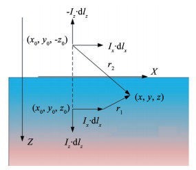 图 2 电偶极子的单界面镜像模型 Fig. 2 Mirror model of dipole of single interface
 2.1 水平静态电偶极子的电场解析式对于水平静态电偶极子,假设海水中任意一点的坐标为(x, y, z),记电偶极子和镜像电偶极子位置与该点距离分别为r1,r2,水平静态电偶极子在此点产生的电位方程为
$\begin{equation*}\varphi_{x}=\frac{I_{x} \cdot \mathrm{d} l_{x}}{4 \pi \sigma_{1}}\left(\frac{x-x_{0}}{r_{1}^{3}}+\frac{x-x_{0}}{r_{2}^{3}}\right) \end{equation*}$ (16)
分别对此电位进行X、Y、Z三个方向的求导,就可以得到X、Y、Z三个方向的电场强度方程[17]分别为
$E_{x x}=\frac{I_{x} \cdot \mathrm{d} l_{x}}{4 \pi \sigma_{1}}\left[\frac{3\left(x-x_{0}\right)^{2}-r_{1}^{2}}{r_{1}^{5}}+\frac{3\left(x-x_{0}\right)^{2}-r_{2}^{2}}{r_{2}^{5}}\right]$ (17)
$E_{y x}=\frac{I_{x} \cdot \mathrm{d} l_{x}}{4 \pi \sigma_{1}}\left[\frac{3\left(x-x_{0}\right)\left(y-y_{0}\right)}{r_{1}^{5}}+\frac{3\left(x-x_{0}\right)\left(y-y_{0}\right)}{r_{2}^{5}}\right]$ (18)
$E_{z x}=\frac{I_{x} \cdot \mathrm{d} l_{x}}{4 \pi \sigma_{1}}\left[\frac{3\left(x-x_{0}\right)\left(z-z_{0}\right)}{r_{1}^{5}}+\frac{3\left(x-x_{0}\right)\left(z+z_{0}\right)}{r_{2}^{5}}\right]$ (19)
总的电场强度方程为
$\left|E_{x}\right|=\sqrt{E_{x x}^{2}+E_{y x}^{2}+E_{z x}^{2}}$
式中:
2.2 垂直静态电偶极子的电场解析式对于垂直静态电偶极子,假设海水中任意一点的坐标为(x, y, z),垂直静态电偶极子在此点产生的电位方程为
$\begin{equation*}\varphi_{z}=\frac{I_{z} \cdot \mathrm{d} l_{z}}{4 \pi \sigma_{1}}\left(\frac{z-z_{0}}{r_{1}^{3}}-\frac{z+z_{0}}{r_{2}^{3}}\right) \end{equation*}$ (20)
分别对此电位进行X、Y、Z三个方向的求导,就可以得到X、Y、Z三个方向的电场强度方程分别为
$E_{x z}=\frac{I_{z} \cdot \mathrm{d} l_{z}}{4 \pi \sigma_{1}}\left[\frac{3\left(x-x_{0}\right)\left(z-z_{0}\right)}{r_{1}^{5}}-\frac{3\left(x-x_{0}\right)\left(z+z_{0}\right)}{r_{2}^{5}}\right]$ (21)
$\begin{equation*}E_{y z}=\frac{I_{z} \cdot \mathrm{d} l_{z}}{4 \pi \sigma_{1}}\left[\frac{3\left(y-y_{0}\right)\left(z-z_{0}\right)}{r_{1}^{5}}-\frac{3\left(y-y_{0}\right)\left(z+z_{0}\right)}{r_{2}^{5}}\right] \end{equation*}$ (22)
$\begin{equation*}E_{z z}=\frac{I_{z} \cdot \mathrm{d} l_{z}}{4 \pi \sigma_{1}}\left[\frac{3\left(z-z_{0}\right)^{2}-r_{1}^{2}}{r_{1}^{5}}-\frac{3\left(z+z_{0}\right)^{2}-r_{2}^{2}}{r_{2}^{5}}\right] \end{equation*}$ (23)
总的电场强度方程为
$\left|E_{z}\right|=\sqrt{E_{x z}^{2}+E_{y z}^{2}+E_{z z}^{2}}$
式中:
2.3 基于舰艇腐蚀电流电偶极子的电场解析式前文已经介绍过,基于舰艇腐蚀电流的电偶极子只需要分解为X、Z两个方向,故水中任意点(x, y, z)的电位方程为
$\begin{gather*}\varphi=\varphi_{x}+\varphi_{z}=\frac{I_{x} \cdot \mathrm{d} l_{x}}{4 \pi \sigma_{1}}\left(\frac{x-x_{0}}{r_{1}^{3}}+\frac{x-x_{0}}{r_{2}^{3}}\right)+ \\\frac{I_{z} \cdot \mathrm{d} l_{z}}{4 \pi \sigma_{1}}\left(\frac{z-z_{0}}{r_{1}^{3}}-\frac{z+z_{0}}{r_{2}^{3}}\right) \end{gather*}$ (24)
假设此腐蚀电流电偶极子与X坐标夹角为?,则在计算水下电场时将此腐蚀电流电偶极子分解为X、Z两个方向。X方向的电偶极子为ig·dlcos ?,Z方向的电偶极子为ig·dlsin ?。
将式(15)代入式(24),可得
$\begin{gather*}\varphi=\varphi_{x}+\varphi_{z}=\frac{i_{\mathrm{g}} \cdot \mathrm{d} l \cos \phi}{4 \pi \sigma_{1}}\left(\frac{x-x_{0}}{r_{1}^{3}}+\frac{x-x_{0}}{r_{2}^{3}}\right)+ \\\frac{i_{\mathrm{g}} \cdot \mathrm{d} l \sin \phi}{4 \pi \sigma_{1}}\left(\frac{z-z_{0}}{r_{1}^{3}}-\frac{z+z_{0}}{r_{2}^{3}}\right) \end{gather*}$ (25)
分别对此电位进行X、Y、Z三个方向的求导,就可以得到X、Y、Z三个方向的电场强度方程分别为
$E_{x}=\frac{i_{\mathrm{g}} \cdot \mathrm{d} l \cos \phi}{4 \pi \sigma_{1}}\left[\frac{3\left(x-x_{0}\right)^{2}-r_{1}^{2}}{r_{1}^{5}}+\frac{3\left(x-x_{0}\right)^{2}-r_{2}^{2}}{r_{2}^{5}}\right]+\\ \frac{i_{\mathrm{g}} \cdot \mathrm{d} l \sin \phi}{4 \pi \sigma_{1}}\left[\frac{3\left(x-x_{0}\right)\left(z-z_{0}\right)}{r_{1}^{5}}-\frac{3\left(x-x_{0}\right)\left(z+z_{0}\right)}{r_{2}^{5}}\right]$ (26)
$\begin{gather*}E_{y}=\frac{i_{\mathrm{g}} \cdot \mathrm{d} l \cos \phi}{4 \pi \sigma_{1}}\left[\frac{3\left(x-x_{0}\right)\left(y-y_{0}\right)}{r_{1}^{5}}+\frac{3\left(x-x_{0}\right)\left(y-y_{0}\right)}{r_{2}^{5}}\right]+ \\\frac{i_{\mathrm{g}} \cdot \mathrm{d} l \sin \phi}{4 \pi \sigma_{1}}\left[\frac{3\left(y-y_{0}\right)\left(z-z_{0}\right)}{r_{1}^{5}}-\frac{3\left(y-y_{0}\right)\left(z+z_{0}\right)}{r_{2}^{5}}\right]\end{gather*}$ (27)
$\begin{align*}E_{z}= & \frac{i_{\mathrm{g}} \cdot \mathrm{d} l \cos \phi}{4 \pi \sigma_{1}}\left[\frac{3\left(x-x_{0}\right)\left(z-z_{0}\right)}{r_{1}^{5}}+\frac{3\left(x-x_{0}\right)\left(z+z_{0}\right)}{r_{2}^{5}}\right]+ \\& \frac{i_{\mathrm{g}} \cdot \mathrm{d} l \sin \phi}{4 \pi \sigma_{1}}\left[\frac{3\left(z-z_{0}\right)^{2}-r_{1}^{2}}{r_{1}^{5}}-\frac{3\left(z+z_{0}\right)^{2}-r_{2}^{2}}{r_{2}^{5}}\right] \end{align*}$ (28)
总的电场强度方程为
$|E|=\sqrt{E_{x}^{2}+E_{y}^{2}+E_{z}^{2}}$
其中
3 影响舰艇水下腐蚀静电场因素的仿真分析 3.1 水下腐蚀静电场仿真模型建立在基于腐蚀电流舰艇水下腐蚀静电场表达式中,可以发现船体和螺旋桨的腐蚀电位分别为φcorr,Fe、φcorr,Cu,则船体-螺旋桨的电位差ΔU=φcorr,Cu-φcorr,Fe,船体和螺旋桨的浸水面积AFe、ACu,海水温度T,海水电导率σ1这些因素都会对舰艇水下腐蚀静电场产生影响。
在第2节的理论分析的基础上,利用MATLAB编程建立计算海水空间中电位和电场分布的数值模型,模型设计步骤如下:1)建立腐蚀电场的O-XYZ直角坐标系,设定船体和螺旋桨等效点坐标位置,以及仿真过程中各参数值;2)利用式(15)计算船体-螺旋桨电偶腐蚀时海水电路中的腐蚀电流ig;3)在得到腐蚀电流ig后,利用式(25)计算海水中各测点的电位,最终利用式(26)、(27)、(28)计算海水中设定测点处X、Y、Z三分量电场和模值。
根据一艘中型舰艇的参数计算其腐蚀电流和水下腐蚀静电场。在XYZ坐标系中,船体等效点的坐标(x0, y0, z0)为(0, 0, 8),螺旋桨等效点坐标(x1, y1, z1) 为(50, 0, 6)。同时,φcorr,Fe=-0.64 V,φcorr,Cu= -0.32 V,AFe=3 000 m2,ACu=50 m2;n=1,βa, Fe= 2.925,βc, Cu=2.846,F=96 485 C/mol,Ka0cR=1.72×10-3 A·cm2,σ1=4 S/m,Kk0cO=1.72×10-3 A·cm2,α=0.5,R=8.314,T=298 K。
船体正下方水深50 m处,X方向从-200 m到200 m的测线上的电场强度模值及x、y、z三分量如图 3所示,其中电场强度的x分量和电场强度模值具有相同的峰值;y分量为0;z分量在x分量峰值两侧约±30 m处分别出现了正负峰,幅值约为x分量峰值的2/3,则舰艇水下腐蚀静电场特征可以用电场模值|E|的峰值表示[21]。图 3中电场由峰值位置向远端减小,在接近±200 m时,其电场值几乎为0,对r1和r2进行分析,测点与电偶极子的距离对电场的影响成指数程度变化。
Fig. 3
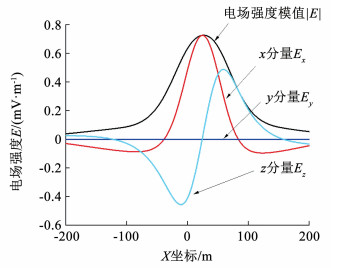 图 3 船体下方50 m测线处电场分布 Fig. 3 Electric field distribution at 50 m below hull
 本节将讨论分析不同影响因素数值变化对舰艇水下腐蚀静电场产生的影响。需要说明的是,以下影响因素的变化范围均根据舰艇和海域实际情况和工程经验得出,例如船体和螺旋桨腐蚀电位的变化范围是以表 1中电极平衡电位为基础的,由于发生电化学反应时,阳极电位正移,阴极电位负移,所以腐蚀电位的变化范围也按照实际情况进行了相应的调整。
3.2 船体和螺旋桨腐蚀电位对舰艇水下腐蚀静电场的影响分析根据常用船体钢材腐蚀电位,设置仿真过程中船体腐蚀电位在-0.45~-0.75 V之间变化。仿真结果如图 4所示。
Fig. 4
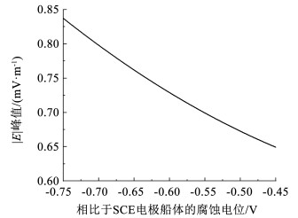 图 4 船体不同腐蚀电位对|E|峰值的影响 Fig. 4 Influence of different corrosion potential of hull on peak value of |E|
 船体正下方50 m处测线结果表明:1)船体材料的腐蚀电位越小,越接近-0.75 V,产生的舰艇水下腐蚀静电场就越大,在式(15)中,由于船体电位为负值,当船体电位增大时,腐蚀电流会减小;2)在其他参数不变,船体腐蚀电位在-0.45~-0.75 V之间变化时,电场强度模值|E|的峰值在0.649~0.838 mV/m之间变化,变化程度大约为29%。
根据常用螺旋桨铜材料腐蚀电位,设置仿真过程中螺旋桨腐蚀电位在-0.15~-0.4 V之间变化。仿真结果如图 5所示。
Fig. 5
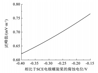 图 5 螺旋桨不同腐蚀电位对|E|峰值的影响 Fig. 5 Influence of different corrosion potential of propeller on peak value of |E|
 船体正下方50 m处测线结果表明:1)螺旋桨材料的腐蚀电位越大,越接近-0.15 V,产生的舰艇水下腐蚀静电场就越大,式(15)阴极电位对腐蚀电流的影响同样说明了这一点,阴极电位越大,腐蚀电流越大;2)在其他参数不变,螺旋桨腐蚀电位在-0.15~-0.4 V之间变化时,电场强度模值|E|的峰值在0.623~0.766 mV/m之间变化,变化程度大约为23%。
3.3 船体和螺旋桨浸水面积对舰艇水下腐蚀静电场的影响分析根据中国常用舰艇船型的船体浸水面积,设置仿真过程中船体浸水面积在2 000~6 000 m2之间变化。仿真结果如图 6所示。
Fig. 6
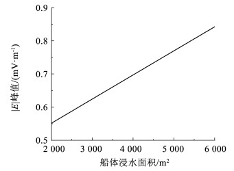 图 6 船体不同浸水面积对|E|峰值的影响 Fig. 6 Influence of different immersion area of hull on peak value of |E|
 船体正下方50 m处测线结果表明:1)船体浸水面积越大,产生的舰艇水下腐蚀静电场就越大。式(11)直接说明了浸水面积和腐蚀电流的正比关系,由于腐蚀电流与电场同样存在正比关系,所以船体浸水面积与电场成正比;2)其他参数不变,船体浸水面积在2 000~6 000 m2之间变化时,电场强度模值|E|的峰值在0.552~0.843 mV/m之间变化,变化程度大约为53%。
根据中国常用舰艇船型螺旋桨浸水面积,设置仿真过程中螺旋桨浸水面积在30~80 m2之间变化。仿真结果如图 7所示。
Fig. 7
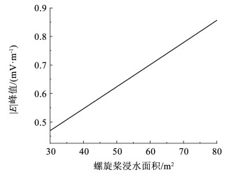 图 7 螺旋桨不同浸水面积对|E|峰值的影响 Fig. 7 Influence of different immersion area of propeller on peak value of |E|
 船体正下方50 m处测线结果表明:1)螺旋桨浸水面积越大,产生的舰艇水下腐蚀静电场就越大。与船体浸水面积同理,都可以用式(11)分析;2)在其他参数不变,螺旋桨浸水面积在30~80 m2之间变化时,电场强度模值|E|的峰值在0.470~0.857 mV/m之间变化,变化程度大约为82%。
3.4 海水温度对舰艇水下腐蚀静电场的影响分析根据中国不同海域的海水温度,设置仿真过程中海水温度在0~30 ℃,即273~303 K之间变化。仿真结果如图 8所示。
Fig. 8
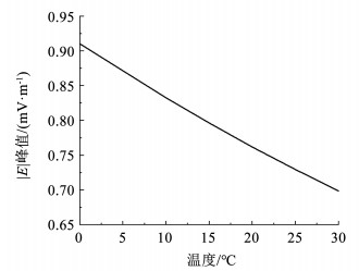 图 8 不同海水温度对|E|峰值的影响 Fig. 8 Influence of different seawater temperature on peak value of |E|
 船体正下方50 m处测线结果表明:1)海水温度越高,产生的舰艇水下腐蚀静电场就越小,温度对腐蚀电流的影响可由式(15)体现,由于热力学温度越接近于0 ℃,温度的倒数越大,其在做e指数时其对电场的影响越大,当热力学温度远大于0 ℃时,温度对电场的影响接近线性。徐庆林等[22]利用有限元仿真同样验证了这一变化趋势;2)在其他参数不变,海水温度在0~30 ℃之间变化时,电场强度模值|E|的峰值在0.699~0.910 mV/m之间,变化程度大约为30%。
3.5 海水电导率对舰艇水下腐蚀静电场的影响分析根据中国不同海域的海水电导率,设置海水电导率在3~5 S/m之间变化。仿真结果如图 9所示。
Fig. 9
 图 9 不同海水电导率对|E|峰值的影响 Fig. 9 Influence of different seawater conductivity on the peak value of |E|
 船体正下方50 m处测线结果表明:1)海水电导率越高,产生的舰艇水下腐蚀静电场就越小,如式(26)、(27)、(28)中,电场与电导率成反比。Schaefer等[21]的研究同样说明了这一结论;2)在其他参数不变,在3~5 S/m之间变化时,电场强度模值|E|的峰值在0.500~0.833 mV/m之间变化,变化程度大约为67%。
4 结论本文从电化学方面对舰艇水下电场的产生机理和分布特性进行了详细分析,讨论了制造舰艇金属材料的腐蚀电化学原理和特性,分析了腐蚀电流的产生机理和基于镜像法的电场计算方法,主要研究结论如下:
1) 在推导出船体-螺旋桨电偶腐蚀电流表达式、空气-海水两层介质下电偶极子电场解析式的基础上,得出了基于舰艇腐蚀电流电偶极子的电场解析式。
2) 通过仿真分析研究了船体和螺旋桨腐蚀电位、船体和螺旋桨浸水面积、海水温度、海水电导率这些因素对舰艇水下腐蚀静电场的影响,验证了所推导电场解析式的准确性。研究结果表明:船体腐蚀电位、螺旋桨腐蚀电位、海水温度对舰艇水下静电场的影响较小,在设定范围内其电场变化程度分别为29%、23%、30%。而船体浸水面积、螺旋桨浸水面积、海水电导率对舰艇水下腐蚀静电场影响较为显著,在设定范围内其电场变化程度分别为53%、82%、67%。
参考文献
[1] 臧燕华, 岳瑞永, 李沛剑. 基于边界元理论模型的舰船腐蚀相关电场衰减规律[J]. 舰船科学技术, 2012, 34(1): 11.
ZANG Yanhua, YUE Ruiyong, LI Peijian. Research on attenuation law of the corrosion related electric field based on the boundary element method[J]. Ship Science and Technology, 2012, 34(1): 11.
[2] 张维俊. 舰船隐身技术的研究现状及发展趋势[J]. 造船技术, 2012(1): 1.
ZHANG Weijun. Investigation actuality and development trend of warship stealth technology[J]. Marine Technology, 2012(1): 1. DOI:10.3969/j.issn.1000-3878.2012.01.001
[3] 龚沈光, 卢新城. 舰船电场特性初步分析[J]. 海军工程大学学报, 2008, 20(2): 1.
GONG Shenguang, LU Xincheng. Pilot study of electric characteristics of warsh[J]. Journal of Naval University of Engineering, 2008, 20(2): 1.
[4] SCHAEFER D, DOOSE J, PICHLMAIER M, et al. Conversion of UEP signatures between different environmental conditions using shaft currents[J]. IEEE Journal of Oceanic Engineering, 2015, 41(1): 105.
[5] ADEY R, BAYNHAM J M W. Predicting corrosion related signatures[J]. WIT Transactions on Engineering Sciences, 2007, 54: 213.
[6] 陈聪, 蒋治国, 姚陆锋, 等. 浅海中潜艇腐蚀相关静态电磁信号特征[J]. 海军工程大学学报, 2014, 26(3): 1.
CHEN Cong, JIANG Zhiguo, YAO Lufeng, et al. Characteristic analysis of corrosion-related static electromagnetic field produced by a submarine in shallow sea[J]. Journal of Naval University of Engineering, 2014, 26(3): 1.
[7] 张伽伟, 熊露, 龚沈光. 金属体在海水中运动产生的感应电场建模[J]. 国防科技大学学报, 2013, 35(6): 147.
ZHANG Jiawei, XIONG Lu, GONG Shenguang. Modeling of the electric field generated by metal body moving under seawater[J]. Journal of National University of Defense Technology, 2013, 35(6): 147.
[8] DEMILIER L, DURAND C, RANNOU C, et al. Corrosion related electromagnetic signatures measurements and modelling on a 1∶40th scaled model[J]. WIT Transactions on Engineering Sciences, 2007, 54: 368.
[9] 程锐, 姜润翔, 龚沈光. 船舶轴频电场等效源强度计算方法[J]. 国防科技大学学报, 2016, 38(2): 138.
CHENG Rui, JIANG Runxiang, GONG Shenguang. Calculation method of vessels' shaft rate electric field equivalent source magnitude[J]. Journal of National University of Defense Technology, 2016, 38(2): 138.
[10] WANG Y, KARISALLEN K J. Comparison of impressed current cathodic protection numerical modeling results with physical scale modeling data[J]. Corrosion, 2010, 66(10): 105.
[11] 曹楚南. 腐蚀电化学原理[M]. 北京: 化学工业出版社, 2008.
CAO Chunan. Principles of electrochemistry of corrosion[M]. Beijing: Chemical Industry Press, 2008.
[12] 张济平, 柳懿, 王向军. 舰船静电场防护技术发展综述[J]. 舰船科学技术, 2020, 42(7): 13.
ZHANG Jiping, LIU Yi, WANG Xiangjun. Overview on development of submarine electrostatic field protection technology[J]. Ship Science and Technology, 2020, 42(7): 13.
[13] NEJNERU C, SAVIN C, JU M P, et al. Studies on galvanic corrosion of metallic materials in marine medium[J]. IOP Conference Series Materials Science and Engineering, 2019, 572: 012106.
[14] XING S H, LI Y, SONGH Q, et al. Optimizing the quantity, locations and output current of anodes to improve cathodic protection effect of semi-submersible Crane vessel[J]. Ocean Engineering, 2016, 113: 144.
[15] 谭浩, 陈聪, 蒋治国. 船舶水下电场的预测方法[J]. 国防科技大学学报, 2016, 38(6): 168.
TAN Hao, CHEN Cong, JIANG Zhiguo. Electric field prediction method for ships at sea[J]. Journal of National University of Defense Technology, 2016, 38(6): 168.
[16] 陈聪, 李定国, 龚沈光. 舰船静态电场深度换算方法[J]. 哈尔滨工程大学学报, 2009, 30(6): 719.
CHEN Cong, LI Dingguo, GONG Shenguang. The method of the extrapolation of the static electric field of ships[J]. Journal of Harbin Engineering University, 2009, 30(6): 719.
[17] KEDDIE A J, POCOCK M D, DEGIORGI V G. Fast solution techniques for corrosion and signatures modeling[J]. WIT Transactions on Engineering Sciences, 2007, 54: 225.
[18] 刘文宝, 王向军, 嵇斗. 基于电偶极子模型的舰船静电场深度换算[J]. 空军雷达学院学报, 2010, 24(6): 435.
LIU Wenbao, WANG Xiangjun, JI Dou. Conversion of static electric field depth of ships based on electric dipole model[J]. Journal of Air Force Radar Academy, 2010, 24(6): 435.
[19] 张建春, 王向军. 水平电流元在深海中的电场强度算法研究[J]. 舰船科学技术, 2016, 38(1): 90.
ZHANG Jianchun, WANG Xiangjun. Arithetic research about electric-field intensity of horizontal-harmonic current in the deep sea[J]. Ship Science and Technology, 2016, 38(1): 90.
[20] 李涛, 王向军, 嵇斗. 浅海中时谐水平电偶极子定位研究[J]. 舰船电子工程, 2015, 35(5): 142.
LI Tao, WANG Xiangjun, JI Dou. Time-harmonic horiziontal dipole in coastal[J]. Ship Electronic Engineering, 2015, 35(5): 142.
[21] SCHAEFER D, DOOSE J, PICHLMAIER M, et al. Comparability of UEP signatures measured under varying environmental conditions[C]// The 8th International Marine Electromagnetics Conference (MARELEC 2013). Hamburg: University of Duisburg-Essen, 2013
[22] 徐庆林, 王向军, 张建春, 等. 温度对舰船阴极保护和腐蚀静电场的影响[J]. 国防科技大学学报, 2019, 41(4): 182.
XU Qinglin, WANG Xiangjun, ZHANG Jianchun, et al. Influence of temperature on the cathodic protection and corrosion electrostatic field of ships[J]. Journal of National University of Defense Technology, 2019, 41(4): 182.
