周宁1,吴瀚枭1,杨海鹏1,关威2
(1. 北京宇航系统工程研究所,北京 100076; 2. 哈尔滨工业大学 航天学院,哈尔滨 150001)
摘要:
为进一步实现液体运载火箭贮箱箱底结构轻量化,在实际工况的约束下,综合现役箱底的载荷特点(贮箱箱底厚度参数和火箭运行内压值的理论关系),对贮箱箱底的结构进行参数化。提出剩余强度系数作为贮箱箱底的设计载荷指标,结合工况建立了箱底厚度设计准则,剩余强度系数不小于1时满足工程需要,并以此对箱底厚度进行优化。根据设计准则可以建立开口与箱底厚度的关系,更精确的给定设计箱底临界厚度值。建立的箱底厚度设计准则可以对已设计完成的贮箱箱底进行内压承载能力进行验算。运用实际工况数据验证了设计准则的可用性,并提出了旋压型箱底的厚度分区轻量化方法。此外,根据贮箱箱底管路接口、传感器接口各方面输入输出的交互影响,建立了贮箱箱底开口多约束评估模型。通过参数化平台实现方法的具体实用性及自动化建模。结果表明,旋压型箱底的厚度分区轻量化方法可以实现箱底平均减重约30%。参数化平台和自动化建模为提高贮箱箱底设计效率提供了一种新的方法。
关键词: 液体火箭贮箱 箱底厚度设计准则 箱底轻量化 参数化平台 自动化建模
DOI:10.11918/202305040
分类号:V434
文献标识码:A
基金项目:国家自然科学基金(62063009); 中国科学院赣江创新研究院项目(E255J001)
Design guidelines and lightweighting of liquid launch vehicle tank bottom thickness
ZHOU Ning1,WU Hanxiao1,YANG Haipeng1,GUAN Wei2
(1. Beijing Institute of Aerospace Systems Engineering, Beijing 100076, China; 2. School of Astronautics, Harbin Institute of Technology, Harbin 150001, China)
Abstract:
To further realize lightweighting of the tank bottom structure of liquid launch vehicle tanks, a parametric approach is proposed by considering the load characteristics of existing tank bottoms (thickness parameters and the theoretical relationship with internal pressure during rocket operation) under actual working conditions. The residual strength coefficient is proposed as a design load index of the storage tank bottom, and a design criterion of the tank bottom thickness is established by combining the working conditions. When the residual strength coefficient is not less than 1, the tank bottom thickness is considered satisfactory, meeting the engineering needs, and the thickness of the tank bottom is optimized based on this criterion. According to the design criterion, the relationship between the opening and the bottom thickness can be established, and the critical thickness value of the bottom of the storage tank can be determined more accurately. The established bottom thickness design criterion can be used to verify the internal pressure bearing capacity of the designed storage tank bottom. The usability of the design criterion is validated by using actual working condition data, and a thickness partitioning and lightweighting method for spinning-type tank bottom is proposed. In addition, a multi-constraint evaluation model for the opening of the tank bottom is established based on the interaction of the inputs and outputs of the piping and sensor interfaces of the tank bottom. The specific practicality of the method and automated modeling are realized through a parametric platform. The results show that the thickness partitioning lightweighting method for spinning-type tank bottoms can realize an average weight reduction of about 30% for tank bottoms. The parametric platform and automated modeling provide a new method to improve the efficiency of storage tank bottoms.
Key words: iquid launch vehicle tank bottom thickness design guidelines tanks bottom lightweight parameterized platform automation modeling
周宁, 吴瀚枭, 杨海鹏, 关威. 液体运载火箭贮箱箱底厚度设计准则及轻量化[J]. 哈尔滨工业大学学报, 2024, 56(8): 17-23. DOI: 10.11918/202305040.

ZHOU Ning, WU Hanxiao, YANG Haipeng, GUAN Wei. Design guidelines and lightweighting of liquid launch vehicle tank bottom thickness[J]. Journal of Harbin Institute of Technology, 2024, 56(8): 17-23. DOI: 10.11918/202305040.

作者简介 周宁(1993―),男,工程师;
关威(1982—),男,教授,博士生导师 通信作者 周宁,znbike@163.com 文章历史 收稿日期: 2023-05-14
Abstract Full text Figures/Tables PDF
液体运载火箭贮箱箱底厚度设计准则及轻量化
周宁1

 , 吴瀚枭1, 杨海鹏1, 关威2
 1. 北京宇航系统工程研究所,北京 100076;
2. 哈尔滨工业大学 航天学院,哈尔滨 150001
收稿日期: 2023-05-14; 修改日期: 2023-07-20; 网络首发日期: 2024-05-18
作者简介: 周宁(1993―),男,工程师; 关威(1982—),男,教授,博士生导师
通信作者: 周宁,znbike@163.com
摘要: 为进一步实现液体运载火箭贮箱箱底结构轻量化,在实际工况的约束下,综合现役箱底的载荷特点(贮箱箱底厚度参数和火箭运行内压值的理论关系),对贮箱箱底的结构进行参数化。提出剩余强度系数作为贮箱箱底的设计载荷指标,结合工况建立了箱底厚度设计准则,剩余强度系数不小于1时满足工程需要,并以此对箱底厚度进行优化。根据设计准则可以建立开口与箱底厚度的关系,更精确的给定设计箱底临界厚度值。建立的箱底厚度设计准则可以对已设计完成的贮箱箱底进行内压承载能力进行验算。运用实际工况数据验证了设计准则的可用性,并提出了旋压型箱底的厚度分区轻量化方法。此外,根据贮箱箱底管路接口、传感器接口各方面输入输出的交互影响,建立了贮箱箱底开口多约束评估模型。通过参数化平台实现方法的具体实用性及自动化建模。结果表明,旋压型箱底的厚度分区轻量化方法可以实现箱底平均减重约30%。参数化平台和自动化建模为提高贮箱箱底设计效率提供了一种新的方法。
关键词: 液体火箭贮箱 箱底厚度设计准则 箱底轻量化 参数化平台 自动化建模
Design guidelines and lightweighting of liquid launch vehicle tank bottom thickness
ZHOU Ning1

 , WU Hanxiao1, YANG Haipeng1, GUAN Wei2
 1. Beijing Institute of Aerospace Systems Engineering, Beijing 100076, China;
2. School of Astronautics, Harbin Institute of Technology, Harbin 150001, China
Abstract: To further realize lightweighting of the tank bottom structure of liquid launch vehicle tanks, a parametric approach is proposed by considering the load characteristics of existing tank bottoms (thickness parameters and the theoretical relationship with internal pressure during rocket operation) under actual working conditions. The residual strength coefficient is proposed as a design load index of the storage tank bottom, and a design criterion of the tank bottom thickness is established by combining the working conditions. When the residual strength coefficient is not less than 1, the tank bottom thickness is considered satisfactory, meeting the engineering needs, and the thickness of the tank bottom is optimized based on this criterion. According to the design criterion, the relationship between the opening and the bottom thickness can be established, and the critical thickness value of the bottom of the storage tank can be determined more accurately. The established bottom thickness design criterion can be used to verify the internal pressure bearing capacity of the designed storage tank bottom. The usability of the design criterion is validated by using actual working condition data, and a thickness partitioning and lightweighting method for spinning-type tank bottom is proposed. In addition, a multi-constraint evaluation model for the opening of the tank bottom is established based on the interaction of the inputs and outputs of the piping and sensor interfaces of the tank bottom. The specific practicality of the method and automated modeling are realized through a parametric platform. The results show that the thickness partitioning lightweighting method for spinning-type tank bottoms can realize an average weight reduction of about 30% for tank bottoms. The parametric platform and automated modeling provide a new method to improve the efficiency of storage tank bottoms.
Keywords: iquid launch vehicle tank bottom thickness design guidelines tanks bottom lightweight parameterized platform automation modeling
作为液体运载火箭的重要组成部分,运载火箭贮箱箱底在火箭飞行过程中主要承受过载、箱压等载荷。贮箱箱底的承载能力在整个贮箱设计过程中十分重要,它关系到运载火箭的可靠性和稳定性。因此,研究人员越来越重视贮箱箱底的结构优化设计[1-3]。
传统的贮箱箱底设计主要是通过经验以及参考其他箱底的设计来完成的,而对于不同类型的箱底设计,其计算与后期的校核验算向来都是相对繁琐的过程。举例来说:当箱底的基本参数如箱底尺寸、箱底开孔改变时,设计人员都需要重新进行箱底厚度的设计与载荷校核,这增加了设计时间以及设计成本[3-4]。随着火箭型号越来越多,各型号结构系统设计状态多、工艺繁杂、自动化程度低、生产成本高昂等问题凸显,贮箱结构设计成为制约型号生产、交付的短板,使得贮箱箱底结构设计成为箭体结构设计工作的焦点[5-7]。此外,贮箱结构不仅是成本控制和效率提升的核心,也是火箭结构轻量化的关键。贮箱的质量对火箭的飞行力学、姿态控制和振动环境都将产生一定的影响,需要对火箭贮箱的质量进行严格控制。
为解决上述问题,本文在对液体运载火箭贮箱箱底结构特点和技术现状进行分析的基础上,提出贮箱箱底厚度设计准则以及贮箱结构轻量化思路和具体措施。以贮箱所受承载力为约束条件,以贮箱质量最小为优化目标,进行贮箱箱底轻量化设计。另外,将承载能力和开孔布局计算公式程序化,快速得到贮箱箱底设计结果、载荷校验(承载能力)结果及轻量化结果,为贮箱箱底的研发设计提供新的设计思路与方法。
1 箱底模型液体运载火箭贮箱椭球箱底根据加工工艺分为拼焊箱底和旋压箱底[7]。拼焊箱底由顶盖、若干瓜瓣拼焊组成,如图 1(a)所示。旋压箱底采用局部连续塑性成型工艺进行回转体零件塑性成型,如图 1(b) 所示。旋压箱底的制造综合了锻造、挤压、拉伸、弯曲、环压、横轧和滚压等先进工艺[7-9],这种工艺可以提高材料利用率,提高材料的机械性能,降低制造成本,实现薄壁回转壳体高精度、低成本高效加工,是实现薄壁回转体零件的先进制造技术。两种箱底的长半轴记为a,箱底高度记为b,基体厚度为tj(tj1、tj2),焊缝区厚度为th(th1、th2)如图 1所示。运载火箭箱底外部接口结构主要包括两个部分:一是安装了测量、附加等系统的箱底传感器法兰;二是用于管路系统安装对接的法兰,一般包括人孔、加注口、隧道管口、保险阀口、排气阀口、增压口、箱内压力传感器安装口、箱内温度传感器安装口、液位传感器安装口、溢出管口等。各个型号贮箱的开口数量和开口位置有差别,其中人孔和隧道管口直径大,传感器类开孔多布置在人孔盖上。火箭飞行过程中箱底顶点的载荷最大,所以常以中心开孔(顶盖开孔)为基准设计和验证箱底承载能力。在拼焊箱底中影响承载能力,开孔法兰、各瓜瓣间均需要焊接,焊缝的分布范围越大箱底质量就越大。拼焊箱底各瓜瓣间破坏了材料的连续性,焊缝是整个箱底上最薄弱的环节。焊接中容易产生气孔、变形、裂纹等缺陷,影响箱底的可靠性和合格率[10-13]。旋压工艺整体成型可以减少拼焊箱底瓜瓣间的焊接,但在旋压箱底中,开孔法兰与箱底间仍需要焊接,为保证箱底的承载能力,避免局部应力的影响,加厚开孔法兰焊接的环形区域,该区域定义为厚区。厚区的厚度和开孔法兰与箱底间需要焊接的焊缝厚度一致。
Fig. 1
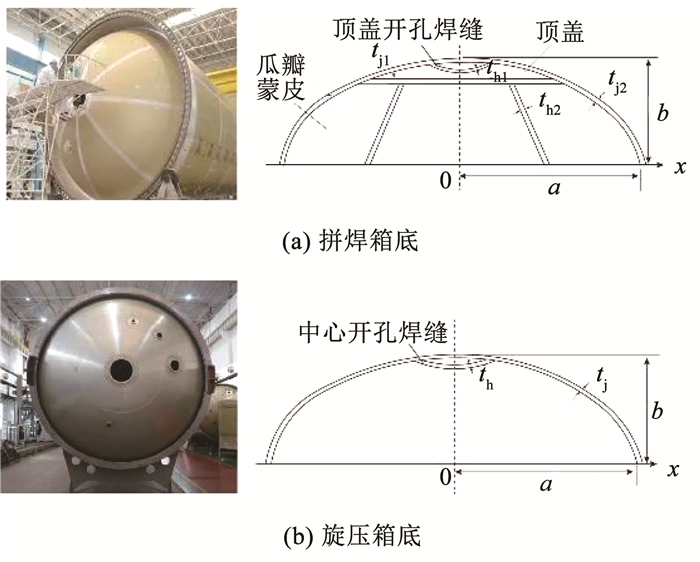 图 1 贮箱椭球箱底示意 Fig. 1 Schematic diagram of ellipsoidal tank bottom
 2 箱底厚度设计准则及轻量化 2.1 箱底厚度设计准则火箭贮箱箱底的承载能力决定了运载火箭的可靠性和稳定性,在整个贮箱设计过程中十分重要[14-16]。本文通过对各个型号的贮箱箱底载荷进行梳理和计算发现:影响贮箱前、后底的主要载荷是火箭飞行过载和内压等指标,指标不同导致箱底承载能力不同、结构尺寸存在差别[17-18]。本文根据贮箱箱底的承载能力,提出了剩余强度系数η≥1作为箱底厚度设计准则。
根据设计准则可以建立开口与箱底厚度的关系,更精确的给定设计箱底临界厚度值。总的来说,设计准则的应用分为两个部分:箱底厚度设计和箱底承载能力验算。
以下将具体介绍剩余强度系数η的计算。火箭飞行过程中,贮箱前、后底承受内压载荷,通过对运行各时段的内压值进行比较获得最大内压值,按最大内压设计情况下的Pz (增压压力)、Pq (推进剂液柱产生的压力)值计算基体和焊缝(厚区)厚度。使用内压为
$\begin{equation*}P^{\mathrm{s}}=P_{\mathrm{z}}+P_{\mathrm{q}} \end{equation*}$ (1)
在箱底厚度设计中,根据实际工况计算基体设计内压:
$\begin{equation*}P_{\mathrm{j}}^{J}=f_{\mathrm{j}} P^{\mathrm{s}} \end{equation*}$ (2)
式中:PjJ为基体设计内压,fj为基体安全系数,Ps为使用内压。
焊缝(厚区)设计内压:
$\begin{equation*}P_{\mathrm{h}}^{J}=f_{\mathrm{h}} P^{s} \end{equation*}$ (3)
式中:PhJ为焊缝(厚区)设计内压,fh为焊缝(厚区)安全系数。
箱底厚度由材料属性和使用内压决定的,椭球底基体厚度tj按如下公式计算:
$\begin{equation*}t_{\mathrm{j}}=\frac{P_{\mathrm{j}}^{J} R_{2}}{2 \sigma_{\mathrm{bt}}} \end{equation*}$ (4)
式中:tj为基体厚度计算值;R2为椭球第二主曲率半径,
焊缝区(厚区)厚度th按如下公式计算:
$\begin{equation*}t_{\mathrm{h}}=\frac{P_{\mathrm{h}}^{J} R_{2}}{2 \sigma_{\mathrm{bhh}}} \end{equation*}$ (5)
式中:th为焊缝(厚区)厚度计算值,σbth为焊缝(厚区)抗拉强度。
加工完成的贮箱是否适用实际工程需要根据实际工况进行验算,对箱底内压承载能力进行校验,基体内压承载能力验算:
$P_{\mathrm{j}} =\frac{2 t_{\mathrm{j}} \sigma_{\mathrm{bt}}}{R_{2}} $ (6)
$\eta_{\mathrm{j}} =\frac{P_{\mathrm{j}}}{P_{\mathrm{j}}^{J}} $ (7)
式中:Pj为实际的基体内压承载能力,tj为计算处的基体厚度设计值,ηj为基体内压剩余强度系数。
焊缝(厚区)内压承载能力验算:
$P_{\mathrm{h}}=\frac{2 \sigma_{\mathrm{bt}} \times \varphi \times t_{\mathrm{h}}}{R_{2}} $ (8)
$\eta_{\mathrm{h}}=\frac{P_{\mathrm{h}}}{P_{\mathrm{h}}^{J}} $ (9)
式中:Ph为实际的焊缝(厚区)内压承载能力,th为计算处的焊缝(厚区)厚度设计值,ηh为焊缝(厚区)内压剩余强度系数,当η≥1时符合设计准则,满足工况需要。
2.2 箱底厚度设计准则应用及轻量化设计以某型号现役燃料贮箱拼焊型椭球箱底为例说明箱底厚度设计准则的应用。贮箱结构材料选用2219铝合金。前、后底型面为a=1 669 mm,m= a/b=1.6的旋转椭球面,由顶盖和8块瓜瓣焊接而成。
前底焊接区厚度为5.5 mm,蒙皮区厚度为2.2 mm。在实际工况下,贮箱压力变化范围上限为Pz=0.45 MPa, t=110 ℃,则设计载荷为PjJ=0.68 MPa, PhJ=0.73 MPa。实际后底焊接区厚度为6.5 mm,蒙皮区厚度为2.8 mm。后底最大使用载荷为Pz=154.8 kPa,Pq=154.8 kPa,t=-182 ℃,则设计载荷为PjJ=0.786 MPa,PhJ=0.847 MPa。其他参数为x=690 mm, σbt=480 MPa,φ=0.5,fj=1.3,fh=1.4,箱底剩余强度系数和质量估算见表 1。η≥1说明贮箱箱底承载能力,符合设计准则,满足工程需要。以此为例运用现役箱底参数验证了上述设计准则的可用性。
表 1
前底 焊缝区Ph 0.741 焊缝区 1.10 136.7
基体Pj 0.680 基体 1.00
后底 焊缝区Ph 0.970 焊缝区 1.14 180.6
基体Pj 0.912 基体 1.16
表 1 某型号燃料贮箱拼焊箱底剩余强度系数和质量估算 Tab. 1 Residual strength coefficient and weight estimation of welded tank bottom for a certain fuel tank model
贮箱箱底用整体旋压技术替代传统的瓜瓣拼焊工艺,一方面可实现大型贮箱结构整体化、高精度的技术要求,另一方面可显著减轻贮箱质量,节约生产成本,缩短周期。本文轻量化设计主要应用在旋压式箱底。以上述某型号燃料贮箱拼焊箱底为例,将拼焊箱改为旋压箱底,并进行轻量化设计。在上述已知实际工况时,设计贮箱箱底厚度需要满足式(4)、(5)。在椭球半长轴与模数确定的情况下,箱底基体蒙皮区厚度为关于x的一元函数,x越大厚度越小,即越靠近箱底边缘所需厚度越薄示意图如图 2所示,关系如下:
$ \begin{equation*}t_{\mathrm{j}}=\frac{f_{\mathrm{j}} P^{\mathrm{s}}}{2 \sigma_{\mathrm{bt}}} m \sqrt{a^{2}-x^{2}\left(1-\frac{1}{m^{2}}\right)} \end{equation*} $ (10)
Fig. 2
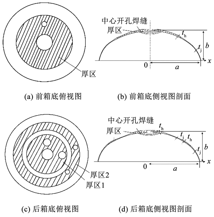 图 2 轻量化旋压箱底示意 Fig. 2 Schematic diagram of lightweight spinning tank bottom
 厚区所需厚度同样为关于x的一元函数,即越靠近箱底边缘所需厚度越薄,关系如下:
$ \begin{equation*}t_{\mathrm{h}}=\frac{f_{\mathrm{h}} P^{\mathrm{s}}}{2 \sigma_{\mathrm{bl}} \varphi} m \sqrt{a^{2}-x^{2}\left(1-\frac{1}{m^{2}}\right)} \end{equation*} $ (11)
前底厚区计算位置x起始为310~190 mm,基体计算位置x起始为1 190~1 669 mm。后底厚区计算位置x起始为厚区1(99~987 mm),厚区2(1 289~1 624 mm),基体计算位置x起始为基体1(987~1 289 mm),基体2(1642~1 669 mm)。通过式(10)、(11)计算某型号燃料贮箱旋压箱底临界厚度见表 2。体积和密度计算得到箱底质量统计在表 2中。对比表 1、2,相同贮箱箱底可以实现前底减重约35 %,后底减重约25 %。如果箱底有更多的减重需求,可在环形加厚箱底的基础上,铣去部分扇形区域减重,即仅保留开孔周围焊缝区(厚区)。
表 2
前底 厚区 3.8~3.2 88.9
基体 1.5~1.2
后底 厚区 厚区15.1~4.5
厚区24.1~3.3 134.7
基体 基体12.1~1.8
基体21.6~1.5
表 2 某型号燃料贮箱旋压箱底临界厚度和质量估算 Tab. 2 Residual strength coefficient and weight estimation of a certain of spin fuel tank bottom
3 参数化平台设计及自动建模利用先进制造工艺构建模块化建模平台,可以大幅缩减设计工序,提高结构产品设计效率。如图 3所示为贮箱箱底自动化建模和载荷校核的平台设计方案框图。梳理现役型号的箱底外形、载荷、开孔,分析工况,总结开孔布局原则作为约束条件与箱底设计准则集成到平台。运用CATIA的曲面造型功能和多种二次开发接口,通过对CATIA软件的二次开发,可以实现贮箱箱底的三维模型自动生成。
Fig. 3
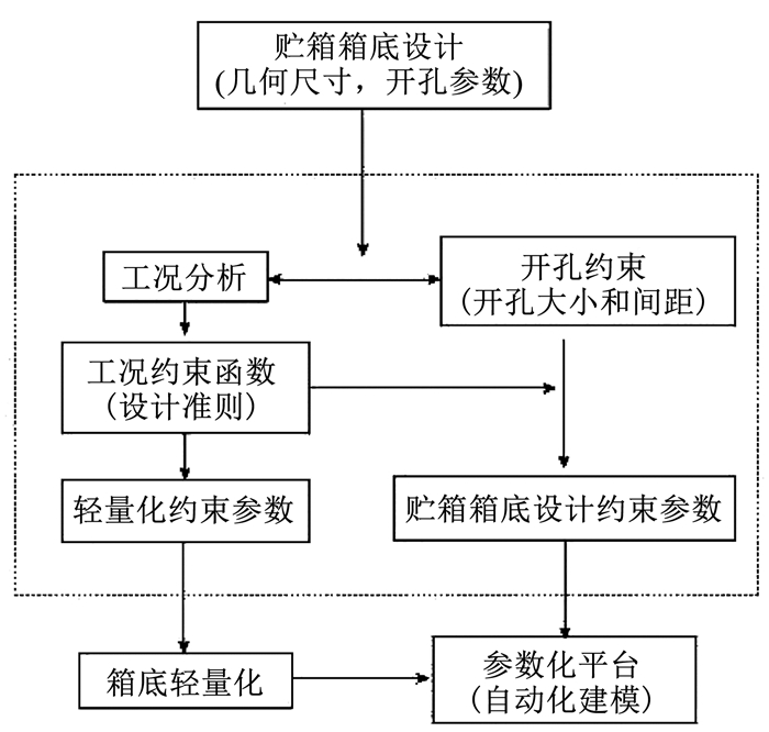 图 3 平台设计方案 Fig. 3 Platform design proposal
 通过编程访问CATIA的对象一般有两种方法,分别是进程内访问和进程外访问[19-22]。第1种方法是在进程内通过VBScript脚本或VBA来访问,脚本和CATIA是在同一进程内运行的;第2种方法即CATIA软件与开发的外部应用程序在不同进程地址空间运行,在进程外通过OLE自动化对象来访问,CATIA作为一个OLE自动化对象服务器,脚本运行通常不由CATIA来调用,需要先将外部脚本程序连接到CATIA上。而Python作为一款功能强大的计算机辅助计算软件,可以进行矩阵运算、图形绘制、创建用户界面、运动仿真等各项功能,在工程等领域中都有非常广阔的应用。故本文考虑在Python/VB语言环境下开发贮箱箱底参数化平台。基于Python对CATIA进行二次开发,实现参数化建模。具体实现方法是通过编写可以操作CATIA的Python脚本,一次性地录制CATIA建模的VB宏。剔除VB宏中冗余信息以保证代码简洁性。从VB宏中找出相应结构参数位置,将具体数字用参数替代。以此实现Python操作CATIA的参数化建模。
焊缝和厚区分布由开孔位置决定。Python脚本读入箱底的结构参数信息,包括前、后底的各个开口的位置及尺寸。根据现役椭球箱底特征,以极坐标形式表示开孔位置。进行箱底设计时结合开孔尺寸,做如下定义简化:图 4中ρ为开口圆心径向位置, φ为开口圆心位置角度,r为开孔半径。图 4中孔1可表示为(ρ, φ, r)。
Fig. 4
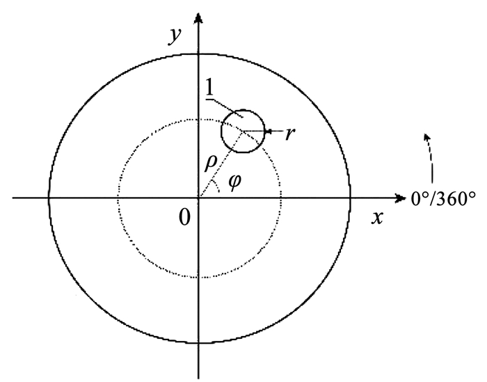 图 4 椭球箱底开孔参数化示意 Fig. 4 Parametric schematic of ellipsoidal tank bottom opening hole
 Python脚本判断各个开口是否符合开孔约束。开孔约束是通过对现役箱底和实际工况进行总结所得到的约束。例如,孔口间不能距离过近,孔口不能距离焊缝过近。要求人口孔盖上的孔口间至少保持40 mm的距离,其他位置的孔口间至少保持80 mm的距离,孔口距离焊缝至少有80 mm的距离。所有焊缝单边50 mm范围内不允许有其他开口或焊缝,所有开口在开口通径基础上单边预留50 mm作为焊缝中心位置。在统型中已知焊缝直径,焊缝直径外边缘预留50 mm。设计箱底时需要注意旋压箱底的厚区宽度,厚区的内边界和外边界覆盖开口包络边界80 mm的范围。要求尽量减少厚区宽度以节省材料,减轻箱底质量。将这些开孔约束转化为数学公式,例如:
$\begin{equation*}l>r_{1}+r_{2}+2 w \end{equation*}$ (12)
式中: l为开孔间距,r1为开孔1的半径,r2为开孔2的半径,w为焊缝宽度。
Python脚本通过Matplotlib模块绘制草图供用户预览。以现役某燃箱的后底的结构参数信息为例,前、后底草图如图 5所示。
Fig. 5
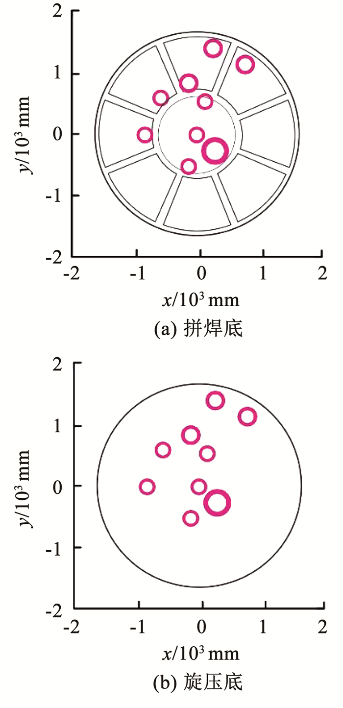 图 5 平台预览草图 Fig. 5 Platform preview sketch
 Python脚本调用CATIA并将建模数据输入CATIA自行建模。对应图 5预览草图,自动建模如图 6所示。
Fig. 6
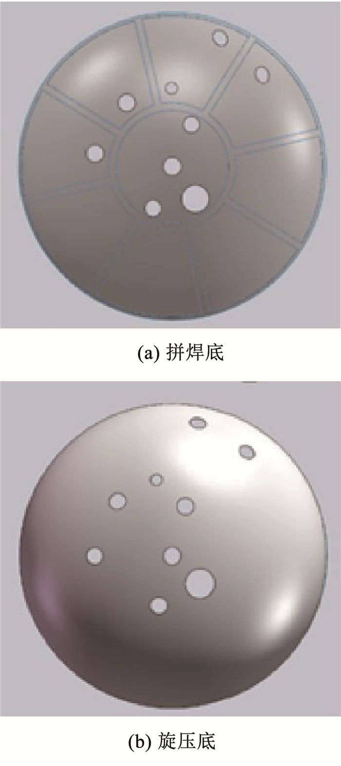 图 6 平台调用CATIA自动化建三维模型 Fig. 6 Platform invokes CATIA automation to build 3D models
 基于PyQT5利用Python语言将上述开孔约束、自动化建模过程、载荷理论以及轻量化算法集成建立一体化平台。平台包括开口布局模块、厚度设计模块和承载能力校验模块。可根据输入参数自动计算最优的箱底厚度,并可反向验算箱底参数是否满足工况承载能力要求(载荷校核)。根据箱底结构及设计目的,将开口设计、厚度设计和载荷校核功能,应用平台进行贮箱设计,实现全参数化和可视化的贮箱产品化设计。
开口布局模块如图 7所示,确定加工工艺(旋压或者拼焊)和结构尺寸等几何参数。根据贮箱箱底管路接口、传感器接口各方面输入、输出的交互影响,建立了贮箱箱底开口多约束评估模型,即图 7中“检查”按键。厚度设计模块如图 8所示,根据工况载荷计算出箱底各部分厚度临界值,为具体的箱体设计提供参考。厚度计算包括两个模块厚度计算和厚度优化。厚度计算是根据计算式(4)、(5)对厚度值进行简单计算。厚度优化是根据计算式(10)、(11)针对整体厚度较大的箱底可以选择厚度优化。保持各位置点的剩余强度系数恒定,进行渐变厚度的设计。实现减小贮箱的质量同时满足设计要求的目的。预览后箱底布局满足工程需求,在平台点击“生成模型”,实现自动化建模,模型建成自动保存成零件文件。载荷校验模块如图 9所示,输入设计承载能力(作为参考计算值)、箱底长半轴、模数、箱体厚度、材料强度系数(基体和焊缝的抗拉强度系数等所建模型参数)等,计算各部分剩余强度系数,η>1满足工况需要,η < 1时设计箱体不满足工程需要。
Fig. 7
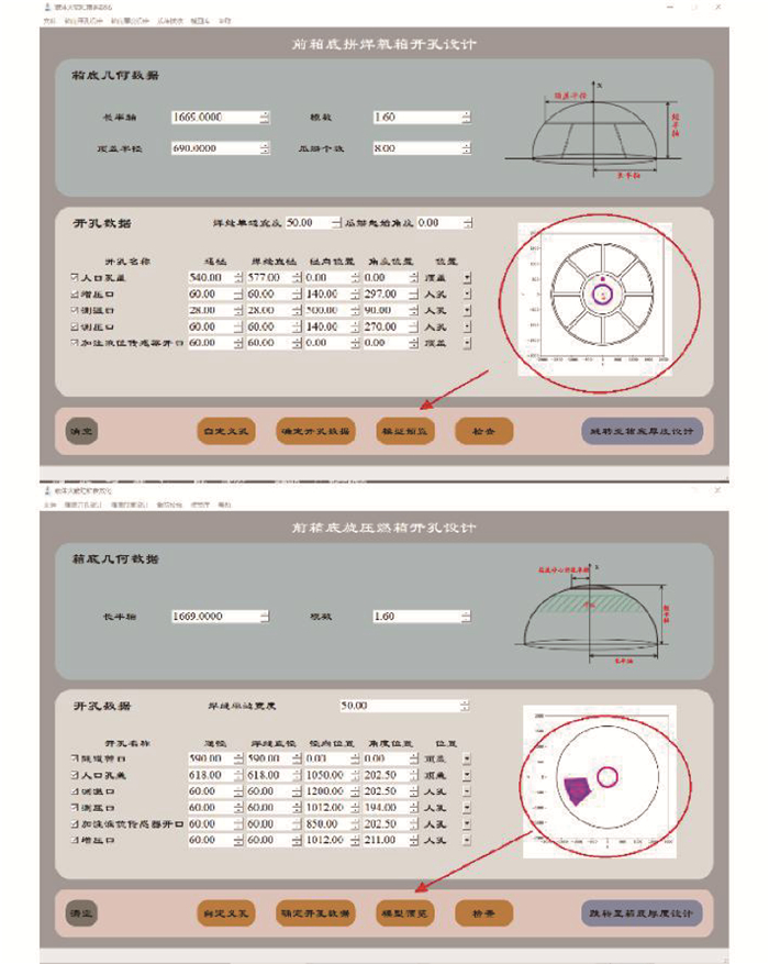 图 7 开口布局模块示意 Fig. 7 Schematic diagram of open-hole layout module
 Fig. 8
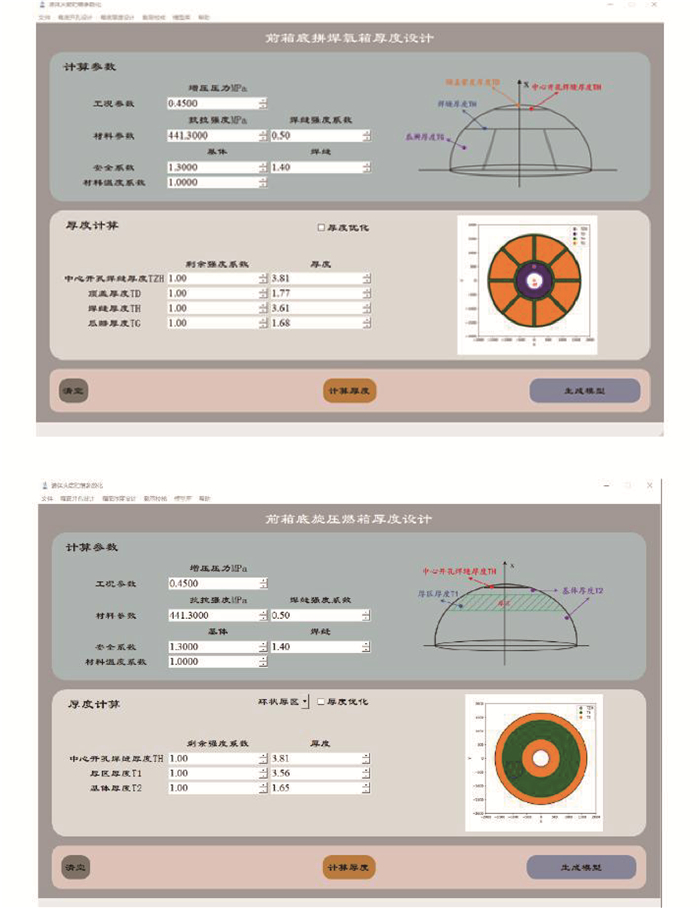 图 8 厚度设计模块示意 Fig. 8 Schematic diagram of thickness design module
 Fig. 9
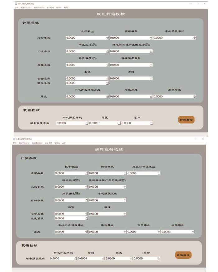 图 9 载荷校核模块示意 Fig. 9 Schematic diagram of load calibration module
 4 结论1) 综合了现役箱底的载荷特点,基于贮箱箱底厚度参数和火箭运行内压值的理论关系,提出了贮箱箱底厚度的设计准则,建立了贮箱箱底承载能力和厚度设计参考系统,实现了箱底结构的参数化。
2) 运用箱底厚度设计准则更精确的给定设计箱底临界厚度值。采用旋压型箱底的厚度分区设计方法进一步优化箱底厚度,实现了箱底平均减重约30%。
3) 综合应用Python和CATIA,将箱底工艺选型、箱底尺寸设计、开孔布局、箱底载荷校验、箱底厚度优化和自动化建模这一完整的分析设计流程集成为贮箱箱底参数化平台。平台可以根据不同的贮箱的基本参数,设计出满足工况需求的箱底结构。在实现箱底轻量化的同时实现快速自动化建模。此外,平台可以对已设计完成的贮箱箱底进行内压承载能力进行验算。为贮箱箱底的研发设计提供设计思路与方法。
参考文献
[1] 王心清. 结构设计[M]. 2版. 北京: 中国宇航出版社, 2009: 19.
WANG Xinqing. Structural design[M]. 2nd ed. Beijing: China Aerospace Press, 2009: 19.
[2] 吴小宁, 赵国柱, 卢兆勇, 等. 国外运载火箭典型结构制造工艺研究[J]. 航天制造技术, 2016(4): 63.
WU Xiaoning, ZHAO Guozhu, LU Zhaoyong, et al. Research of manufacturing process of forgeign launch vehicle typical structures[J]. Aerospace Manufacturing Technology, 2016(4): 63.
[3] 姚君山, 蔡益飞, 李程刚. 运载火箭箭体结构制造技术发展与应用[J]. 航空制造技术, 2007, 50(10): 36.
YAO Junshan, CAI Yifei, LI Chenggang. Development and application of manufacturing technology for rocket body structure of launch vehicle[J]. Aeronautical Manufacturing Technology, 2007, 50(10): 36. DOI:10.3969/j.issn.1671-833X.2007.10.003
[4] 吴会强, 黄诚, 常志龙. 国外大型贮箱结构研制现状及展望[J]. 宇航材料工艺, 2014, 44(Sup.1): 7.
WU Huiqiang, HUANG Cheng, CHANG Zhilong. Recent progress and prospects of large foreign tank structure[J]. Aerospace Materials & Technology, 2014, 44(Sup.1): 7. DOI:10.3969/j.issn.1007-2330.2014.Z1.002
[5] 郑正路, 叶青, 李烁, 等. 运载火箭箭体结构低成本途径及性能影响分析[J]. 航天制造技术, 2019(6): 11.
ZHENG Zhenglu, YE Qing, LI Shuo, et al. Analysis of low cost approach of launch vehicle structure and performance impact[J]. Aerospace Manufacturing Technology, 2019(6): 11. DOI:10.3969/j.issn.1674-5108.2019.06.003
[6] 王腾, 张茜, 李澍, 等. 运载火箭贮箱典型结构件自主统一造型方法研究[J]. 导弹与航天运载技术, 2020(6): 33.
WANG Teng, ZHANG Qian, LI Shu, et al. Research for the unified and independent modeling method of the classic parts on the tank of launch vehicle[J]. Missiles and Space Vehicles, 2020(6): 33. DOI:10.7654/j.issn.1004-7182.20200607
[7] 朱平萍, 刘宪力. 大型贮箱结构及工艺性研究[J]. 航天制造技术, 2011(3): 42.
ZHU Pingping, LIU Xianli. Structural and technological research on large tank[J]. Aerospace Manufacturing Technology, 2011(3): 42.
[8] XIA Qinxiang, XIAO Gangfeng, LONG Hui, et al. A review of process advancement of novel metal spinning[J]. International Journal of Machine Tools and Manufacture, 2014, 85: 100. DOI:10.1016/j.ijmachtools.2014.05.005
[9] LEE K, RYU C, CHOI H, et al. Developing trends of spinning process for manufacturing thrust chamber of launch vehicle[J]. Journal of the Korean Society of Propulsion Engineers, 2015, 19(6): 64. DOI:10.6108/kspe.2015.19.6.064
[10] 郑斌. 火箭贮箱超大薄壁结构焊接变形预测与机理研究[D]. 上海: 上海交通大学, 2018
ZHENG Bin. Study on prediction and mechanism of welding distortion for large scale thin-walled structure of propellant tank[D]. Shanghai: Shanghai Jiao Tong University, 2018. DOI: 10.27307/d.cnki.gsjtu.2018.000466
[11] 李辉, 孙斌, 丁森. 火箭贮箱箱底瓜瓣拉深成形数值模拟[J]. 上海航天, 2012, 29(4): 54.
LI Hui, SUN Bin, DING Sen. Numerical simulation of stretch forming process of rocket tank bottom's melon petals spares[J]. Aerospace Shanghai, 2012, 29(4): 54. DOI:10.19328/j.cnki.1006-1630.2012.04.014
[12] 王颖. 焊接制造缺陷对运载火箭贮箱承载力影响的研究[D]. 天津: 天津大学, 2015
WANG Ying. Research of the influence of the welding manufacturing defects on the bearing capacity of the launch vehicle tank[D]. Tianjin: Tianjin University, 2015
[13] 黄诚, 胡正根, 马云龙, 等. 筒段边界对大直径贮箱椭球箱底的内压稳定性影响研究[J]. 强度与环境, 2015, 42(5): 19.
HUANG Cheng, HU Zhenggen, MA Yunlong, et al. Impact study of shell segment boundary on internal pressure stability of the large diameter tank ellipsoid bottom[J]. Structure & Environment Engineering, 2015, 42(5): 19.
[14] TAKAMATSU, 王亚文. H-1运载火箭液氢/液氧贮箱的研制试验[J]. 国外导弹与航天运载器, 1987(4): 33.
[15] KONYUKHOV A S. Dynamic simulation model of liquid-propellant packet scheme launch vehicles[J]. Strength of Materials, 2015, 47(2): 332. DOI:10.1007/s11223-015-9662-y
[16] SIM C H, KIM G S, KIM D G, et al. Computational modal analyses for the propellant tank and small-scaled first-stage models of liquid-propulsion launch vehicles[J]. Journal of Aerospace System Engineering, 2018, 12(3): 18. DOI:10.20910/JASE.2018.12.3.18
[17] 栗山良员, 金昌旭. 液氢液氧火箭贮箱用高强度铝合金及其焊接接头的机械性能[J]. 国外导弹技术, 1980(3): 79.
[18] 王茂, 黄丽莲. 运载火箭构件抗压强度测试的压力自动加载[J]. 哈尔滨工业大学学报, 2002, 34(6): 838.
WANG Mao, HUANG Lilian. Automatic pressure loading system used for anti-pressure intensity test of carrier rocket parts[J]. Journal of Harbin Institute of Technology, 2002, 34(6): 838. DOI:10.3321/j.issn:0367-6234.2002.06.026
[19] GUO Zhongquan, LIU Jianxia, LUO Wencai. Parametric modeling and simulation for aerodynamic design of launch vehicle[J]. Applied Mechanics and Materials, 2011, 101/102: 697. DOI:10.4028/www.scientific.net/amm.101-102.697
[20] ZHANG Guangguo, CHANG Zhibin, LIU Haitao. Parametric modeling for globoidal cam based on CATIA/CAA[J]. Applied Mechanics and Materials, 2011, 88/89: 236. DOI:10.4028/www.scientific.net/amm.88-89.236
[21] XU Wanhong, WANG Guoying, MA Wenxuan. Analysis and construction of automobile steering gear model library based on CATIA[J]. Advanced Materials Research, 2013, 655/656/657: 1702. DOI:10.4028/www.scientific.net/amr.655-657.1702
[22] 胡挺, 吴立军. CATIA二次开发技术基础[M]. 北京: 电子工业出版社, 2006.
HU Ting, WU Lijun. CATIA secondary development technology[M]. Beijing: Publishing House of Electronics Industry, 2006.
