程杨1,吕忠3,孙志鸿1,董梁1,余莉1,2
(1.飞行器环境控制与生命保障工业和信息化部重点实验室(南京航空航天大学),南京 210016;2. 南京航空航天大学 航空学院,南京 210016; 3. 航空工业宏光空降装备有限公司,南京 210022)
摘要:
为减小翼伞系统的着陆速度,提高载荷的着陆安全性,提出了最优雀降高度确定方法,并完成相对雀降高度和着陆速度影响因素及计算模型研究。首先建立了翼伞-载荷系统两体九自由度动力学模型和雀降操纵耦合气动特性模型,更真实地模拟了翼伞-载荷两体之间操纵情况下的运动性能,研究了雀降操纵下翼伞系统的速度、姿态变化,数值结果和文献规律一致,滑翔比最大误差为8.20%。其次,基于该两体模型,以最小垂直着陆速度为优化目标,采用时间二分法确定最优雀降高度,分析了雀降操纵时机对着陆速度的影响。然后,开展了不同初始工况、翼载荷、着陆海拔高度、安装角下翼伞系统最优雀降实施的仿真计算,并采用最小二乘法完成了相对雀降高度、着陆速度的公式拟合。结果表明:初始参数对相对雀降高度几乎没有影响;随着翼载荷及着陆海拔高度的升高,着陆速度及相对雀降实施高度增加;安装角对着陆速度影响不大,但安装角的增大会引起雀降实施高度增加;所提出的相对雀降高度和着陆速度计算模型与仿真结果较为符合,最大误差小于4.00%,表明该计算模型有良好的适用性。
关键词: 翼伞 9自由度模型 雀降操纵 雀降高度 着陆速度
DOI:10.11918/202308068
分类号:V211
文献标识码:A
基金项目:国家自然科学基金(11972192)
Optimization of flare landing maneuver altitude for two-body model of parafoil system
CHENG Yang1,LV Zhong3,SUN Zhihong1,DONG Liang1,YU Li1,2
(1.Key Laboratory of Aircraft Environment Control and Life Support,MIIT (Nanjing University of Aeronautics and Astronautics),Nanjing 210016,China; 2. College of Aerospace Engineering,Nanjing University of Aeronautics and Astronautics, Nanjing 210016,China; 3. AVIC Hongguang Airborne Equipment Co., Ltd., Nanjing 210022,China)
Abstract:
To decrease landing velocity of parafoil system and improve landing safety of payload, a method for determining the optimal flare landing altitude was proposed, and a study on the influencing factors and calculation models of relative flare landing altitude and landing velocity was completed. Firstly, a two-body nine-degree-of-freedom(DOF) dynamic model of the parafoil system and a coupled aerodynamic characteristic model of flare landing control were established, providing a more realistic simulation of the motion performance of the parafoil system under control between two bodies. The velocity and attitude changes of the parafoil system under flare landing control were studied, and the numerical results were consistent with the results in the literature, with a maximum error of 8.20% in glide ratio. Secondly, based on this model, with the minimum vertical landing velocity as the optimization objective, the optimal landing altitude was determined using the time dichotomy method, and the impact of flare maneuver timing on the landing velocity was analyzed. Then, simulation calculations were conducted on the optimal landing altitude under different initial conditions, wing load, landing altitude, and attack angle. The formula fitting of relative flare altitude and landing velocity was completed by the least squares method. It was found that the initial parameters have a minimal effect on the optimal landing altitude. As the wing load and landing altitude increase, the landing velocity and relative landing altitude also increase. The attack angle has a minor impact on the landing velocity, but an increase in the attack angle leads to an increase in the height of flare landing. The relative flare altitude and landing velocity calculation model proposed in this paper is in goof agreement with the numerical calculation results, with a maximum error less than 4.00%, indicating that the calculation model has good applicability.
Key words: parafoil 9DOF model flare maneuver flare altitude landing velocity
程杨, 吕忠, 孙志鸿, 董梁, 余莉. 翼伞系统两体模型雀降操纵高度的优化[J]. 哈尔滨工业大学学报, 2024, 56(8): 34-41. DOI: 10.11918/202308068.

CHENG Yang, LV Zhong, SUN Zhihong, DONG Liang, YU Li. Optimization of flare landing maneuver altitude for two-body model of parafoil system[J]. Journal of Harbin Institute of Technology, 2024, 56(8): 34-41. DOI: 10.11918/202308068.

基金项目 国家自然科学基金(11972192) 作者简介 程杨(2000―),女,硕士研究生;
余莉(1969―),女,教授,博士生导师 通信作者 余莉,yuli_happy@163.com 文章历史 收稿日期: 2023-08-22
Abstract Full text Figures/Tables PDF
翼伞系统两体模型雀降操纵高度的优化
程杨1, 吕忠3, 孙志鸿1, 董梁1, 余莉1,2


1. 飞行器环境控制与生命保障工业和信息化部重点实验室(南京航空航天大学),南京 210016;
2. 南京航空航天大学 航空学院,南京 210016;
3. 航空工业宏光空降装备有限公司,南京 210022
收稿日期: 2023-08-22; 修改日期: 2023-09-18; 网络首发日期: 2024-06-28
基金项目: 国家自然科学基金(11972192)
作者简介: 程杨(2000―),女,硕士研究生; 余莉(1969―),女,教授,博士生导师
通信作者: 余莉,yuli_happy@163.com
摘要: 为减小翼伞系统的着陆速度,提高载荷的着陆安全性,提出了最优雀降高度确定方法,并完成相对雀降高度和着陆速度影响因素及计算模型研究。首先建立了翼伞-载荷系统两体九自由度动力学模型和雀降操纵耦合气动特性模型,更真实地模拟了翼伞-载荷两体之间操纵情况下的运动性能,研究了雀降操纵下翼伞系统的速度、姿态变化,数值结果和文献规律一致,滑翔比最大误差为8.20%。其次,基于该两体模型,以最小垂直着陆速度为优化目标,采用时间二分法确定最优雀降高度,分析了雀降操纵时机对着陆速度的影响。然后,开展了不同初始工况、翼载荷、着陆海拔高度、安装角下翼伞系统最优雀降实施的仿真计算,并采用最小二乘法完成了相对雀降高度、着陆速度的公式拟合。结果表明:初始参数对相对雀降高度几乎没有影响;随着翼载荷及着陆海拔高度的升高,着陆速度及相对雀降实施高度增加;安装角对着陆速度影响不大,但安装角的增大会引起雀降实施高度增加;所提出的相对雀降高度和着陆速度计算模型与仿真结果较为符合,最大误差小于4.00%,表明该计算模型有良好的适用性。
关键词: 翼伞 9自由度模型 雀降操纵 雀降高度 着陆速度
Optimization of flare landing maneuver altitude for two-body model of parafoil system
CHENG Yang1, LV Zhong3, SUN Zhihong1, DONG Liang1, YU Li1,2


1. Key Laboratory of Aircraft Environment Control and Life Support, MIIT (Nanjing University of Aeronautics and Astronautics), Nanjing 210016, China;
2. College of Aerospace Engineering, Nanjing University of Aeronautics and Astronautics, Nanjing 210016, China;
3. AVIC Hongguang Airborne Equipment Co., Ltd., Nanjing 210022, China
Abstract: To decrease landing velocity of parafoil system and improve landing safety of payload, a method for determining the optimal flare landing altitude was proposed, and a study on the influencing factors and calculation models of relative flare landing altitude and landing velocity was completed. Firstly, a two-body nine-degree-of-freedom(DOF) dynamic model of the parafoil system and a coupled aerodynamic characteristic model of flare landing control were established, providing a more realistic simulation of the motion performance of the parafoil system under control between two bodies. The velocity and attitude changes of the parafoil system under flare landing control were studied, and the numerical results were consistent with the results in the literature, with a maximum error of 8.20% in glide ratio. Secondly, based on this model, with the minimum vertical landing velocity as the optimization objective, the optimal landing altitude was determined using the time dichotomy method, and the impact of flare maneuver timing on the landing velocity was analyzed. Then, simulation calculations were conducted on the optimal landing altitude under different initial conditions, wing load, landing altitude, and attack angle. The formula fitting of relative flare altitude and landing velocity was completed by the least squares method. It was found that the initial parameters have a minimal effect on the optimal landing altitude. As the wing load and landing altitude increase, the landing velocity and relative landing altitude also increase. The attack angle has a minor impact on the landing velocity, but an increase in the attack angle leads to an increase in the height of flare landing. The relative flare altitude and landing velocity calculation model proposed in this paper is in goof agreement with the numerical calculation results, with a maximum error less than 4.00%, indicating that the calculation model has good applicability.
Keywords: parafoil 9DOF model flare maneuver flare altitude landing velocity
翼伞具有极优的操纵能力,在精确空投、伞兵空降及运动表演等领域都得到了广泛应用[1-2]。翼伞通过下拉双侧操纵绳使其气动外形发生变化,升力、阻力系数迅速增大,前进速度和垂直速度在着陆前迅速减小[3],使之实现安全着陆的过程称为雀降过程。雀降操纵本质上是一种小心操纵的动力失速 [4]。
目前,国内外学者多采用单体六自由度(6 degree of freedom,6DOF)模型开展翼伞雀降着陆阶段的研究[5-6]。早期开展此项工作代表人物Goodrick等[7-8]提出并建立了系统平动及转动的6DOF模型,对翼伞系统雀降过程进行了仿真研究,通过与试验翼伞下降率、速度等对比,验证了模型的准确性。国内一些学者利用6DOF模型开展了翼伞雀降着陆阶段的研究。卞琨[9]基于雀降着陆操纵时长及平均垂直速度,得到了翼伞进入雀降着陆段的平均高度;胡容[10]针对2种雀降实施高度下着陆速度的对比,得到了相对优化的雀降高度;张兴会等[11]探究了逆风对雀降高度的影响;熊菁[12]则针对翼伞部分结构参数对雀降性能的影响进行了较为深入的研究。
6DOF模型将翼伞与载荷视为固连的刚体,没有考虑到伞-载两体之间的相对运动状态变化。为更好地探究翼伞-载荷体之间的相对运动变化对翼伞雀降着陆阶段的影响规律,一些学者开始进行翼伞系统多体动力学模型下的雀降研究[13-16]。如杨华等[17]基于翼伞系统纵向对称面内的4DOF模型,根据载荷体接地机械能及速度变化得到翼伞安全雀降的高度及时间范围;李东[18]基于9DOF模型,根据速度的合理范围得到相应的雀降高度范围。上述研究可以得到雀降操纵实施的时间或高度范围,但鲜有对最优雀降实施高度方面的研究报道。
本文根据文献[19]建立了翼伞-载荷两体系统9DOF动力学模型,以垂直着陆速度最小为优化目标,采用时间二分法开展了雀降实施高度的优化研究,探究了初始工况、翼载荷、着陆高度及安装角对于最优雀降实施高度、着陆速度的影响,并完成公式拟合,为工程设计提供了理论依据。
1 翼伞系统动力学建模 1.1 坐标系定义本文动力学方程、运动学方程之间的关系涉及到3个坐标系,包括惯性坐标系OeXeYeZe和两类体轴坐标系(伞体坐标系OpXpYpZp、载荷坐标系ObXbYbZb),如图 1所示。
Fig. 1
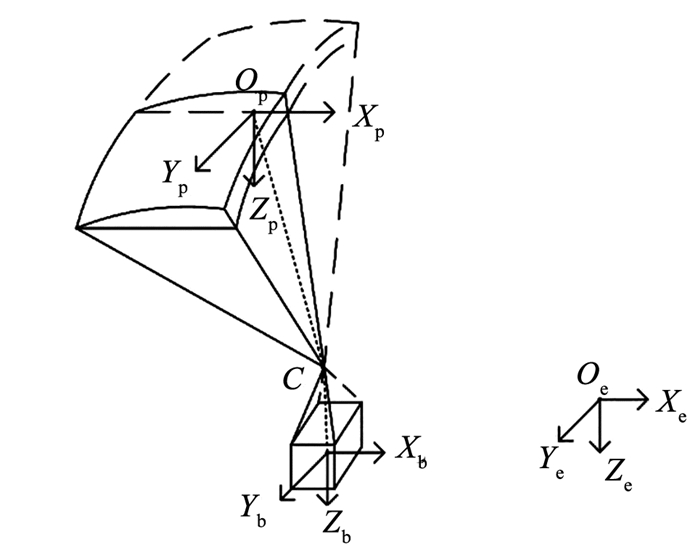 图 1 翼伞系统基本坐标系示意 Fig. 1 Schematic diagram of coordinate systems of parafoil-payload system
 惯性坐标系到体轴系的转换矩阵为
$\boldsymbol{T}_{i}=\left(\begin{array}{ccc}C_{\theta_{i}} C_{\varphi_{i}} & C_{\theta_{i}} S_{\varphi_{i}} &-S_{\theta_{i}} \\S_{\phi_{i}} S_{\theta_{i}} C_{\varphi_{i}}-C_{\phi_{i}} C_{\varphi_{i}} & S_{\phi_{i}} S_{\theta_{i}} S_{\varphi_{i}}+C_{\phi_{i}} C_{\varphi_{i}} & S_{\phi_{i}} C_{\theta_{i}} \\C_{\phi_{i}} S_{\theta_{i}} C_{\varphi_{i}}+S_{\phi_{i}} S_{Q_{i}} & C_{\phi_{i}} S_{\theta_{i}} S_{\varphi_{i}}-S_{\phi_{i}} C_{\varphi_{i}} & C_{\phi_{i}} C_{\theta_{i}}\end{array}\right)$ (1)
式中:C*=cos(*),S*=sin(*);?i为滚转角,θi为俯仰角,φi为偏航角,其中下标i为不同的体轴系。
1.2 9DOF动力学模型本文将翼伞系统中的翼伞、载荷看作是两个中间由球铰连接的刚体,球铰只传递力不传递力矩,翼伞及载荷之间不发生相对移动。因此,翼伞系统的运动模型可简化为系统在连接点(图 1中C点)处的3自由度平动以及翼伞、载荷绕C点的3自由度转动。由此建立刚柔组合系统9DOF动力学模型,动力学方程为
$\left[\begin{array}{cccc}-\boldsymbol M_{\mathrm{b}} \tilde{\boldsymbol R}_{\mathrm{cb}} & 0 & \boldsymbol M_{\mathrm{b}} T_{\mathrm{b}} & \boldsymbol{T}_{\mathrm{b}} \\ 0 &-\left(\boldsymbol M_{\mathrm{p}}+\boldsymbol M_{\mathrm{F}}\right) \tilde{\boldsymbol{R}}_{\mathrm{cp}}&\left(\boldsymbol M_{\mathrm{p}}+\boldsymbol M_{\mathrm{F}}\right) \boldsymbol T_{\mathrm{p}} &-\boldsymbol T_{\mathrm{p}} \\ \boldsymbol I_{\mathrm{b}} & 0 & 0 &-\tilde{\boldsymbol R}_{\mathrm{ch}} \boldsymbol T_{\mathrm{b}} \\ 0 & \boldsymbol I_{\mathrm{p}}+\boldsymbol I_{\mathrm{F}} & 0 & \tilde{\boldsymbol R}_{\mathrm{cp}} \boldsymbol T_{\mathrm{p}}\end{array}\right]\left[\begin{array}{l}\dot{\boldsymbol{\varOmega}}_{\mathrm{b}} \\ \dot{\boldsymbol{\varOmega}}_{\mathrm{p}} \\ {\dot{\boldsymbol V}_{\mathrm{c}}} \\ \boldsymbol F_{\mathrm{c}}\end{array}\right]=\left[\begin{array}{l}\boldsymbol{B}_{1} \\ \boldsymbol{B}_{2} \\ \boldsymbol{B}_{3} \\ \boldsymbol{B}_{4}\end{array}\right]$ (2)
式中
$\left[\begin{array}{l}\boldsymbol B_{1} \\ \boldsymbol B_{2} \\ \boldsymbol B_{3} \\ \boldsymbol B_{4}\end{array}\right]=\left[\begin{array}{c}\left[\begin{array}{c}\boldsymbol{F}_{\mathrm{b}}^{\mathrm{A}}+\boldsymbol{F}_{\mathrm{b}}^{\mathrm{G}}-\tilde{\boldsymbol{\varOmega}}_{\mathrm{b}} \boldsymbol{M}_{\mathrm{b}} \tilde{\boldsymbol{\varOmega}}_{\mathrm{b}} \boldsymbol{R}_{\mathrm{cb}} \\\boldsymbol{F}_{\mathrm{p}}^{\mathrm{A}}+\boldsymbol{F}_{\mathrm{p}}^{\mathrm{G}}-\tilde{\boldsymbol{\varOmega}}_{\mathrm{p}}\left(\boldsymbol{M}_{\mathrm{p}}+\boldsymbol{M}_{\mathrm{F}}\right) \tilde{\boldsymbol{\varOmega}}_{\mathrm{p}} \boldsymbol{R}_{\mathrm{cp}}+\boldsymbol{M}_{\mathrm{F}} \tilde{\boldsymbol{\varOmega}}_{\mathrm{p}} \boldsymbol T_{\mathrm{p}} \boldsymbol{V}_{\mathrm{c}}-\tilde{\boldsymbol{\varOmega}}_{\mathrm{p}} \boldsymbol{M}_{\mathrm{F}} \boldsymbol{T}_{\mathrm{p}} \boldsymbol{V}_{\mathrm{c}} \\\boldsymbol{M}_{\mathrm{b}}^{\mathrm{A}}-\tilde{\boldsymbol{\varOmega}}_{\mathrm{b}} \boldsymbol I_{\mathrm{b}} \boldsymbol{\varOmega}_{\mathrm{b}} \\\boldsymbol{M}_{\mathrm{p}}^{\mathrm{A}}-\tilde{\boldsymbol{\varOmega}}_{\mathrm{p}}\left(\boldsymbol I_{\mathrm{p}}+\boldsymbol I_{\mathrm{F}}\right) \boldsymbol{\varOmega}_{\mathrm{p}}\end{array}\right]\end{array}\right]$ (3)
运动学关系式为:
$\left[\begin{array}{c}\dot{x}_{\mathrm{e}} \\\dot{y}_{\mathrm{e}} \\\dot{z}_{\mathrm{e}}\end{array}\right]=\left[\begin{array}{l}\dot{x}_{\mathrm{c}} \\\dot{y}_{\mathrm{c}} \\\dot{z}_{\mathrm{c}}\end{array}\right]=\left[\begin{array}{c}u_{\mathrm{c}} \\v_{\mathrm{c}} \\w_{\mathrm{c}}\end{array}\right]$ (4)
$\left[\begin{array}{l}u_{\mathrm{p}} \\v_{\mathrm{p}} \\w_{\mathrm{p}}\end{array}\right]=\boldsymbol{T}_{\mathrm{p}}\left[\begin{array}{c}u_{\mathrm{c}} \\v_{\mathrm{c}} \\w_{\mathrm{c}}\end{array}\right]+\dot{\boldsymbol{\varOmega}}_{\mathrm{p}} \boldsymbol{R}_{\mathrm{cp}} $ (5)
$\left[\begin{array}{l}\dot{\phi}_{\mathrm{b}} \\\dot{\theta}_{\mathrm{b}} \\\dot{\varphi}_{\mathrm{b}}\end{array}\right]=\left[\begin{array}{lll}1 & S_{\phi_{\mathrm{b}}} t_{\theta_{\mathrm{b}}} & C_{\phi_{\mathrm{b}}} t_{\theta_{\mathrm{b}}} \\0 & C_{\phi_{\mathrm{b}}} &-S_{\phi_{\mathrm{b}}} \\0 & S_{\phi_{\mathrm{b}}} / C_{\theta_{\mathrm{b}}} & C_{\phi_{\mathrm{b}}} / C_{\theta_{\mathrm{b}}}\end{array}\right]\left[\begin{array}{l}p_{\mathrm{b}} \\q_{\mathrm{b}} \\r_{\mathrm{b}}\end{array}\right]$ (6)
$\left[\begin{array}{l}\dot{\phi}_{\mathrm{p}} \\\dot{\theta}_{\mathrm{p}} \\\dot{\varphi}_{\mathrm{p}}\end{array}\right]=\left[\begin{array}{lll}1 & S_{\phi_{\mathrm{p}}} t_{\theta_{\mathrm{p}}} & C_{\phi_{\mathrm{p}}} t_{\theta_{\mathrm{p}}} \\0 & C_{\phi_{\mathrm{p}}} &-S_{\phi_{\mathrm{p}}} \\0 & S_{\phi_{\mathrm{p}}} / C_{\theta_{\mathrm{p}}} & C_{\phi_{\mathrm{p}_{\mathrm{p}}}} / C_{\theta_{\mathrm{p}}}\end{array}\right]\left[\begin{array}{l}p_{\mathrm{p}} \\q_{\mathrm{p}} \\r_{\mathrm{p}}\end{array}\right]$ (7)
式中:
Fig. 2
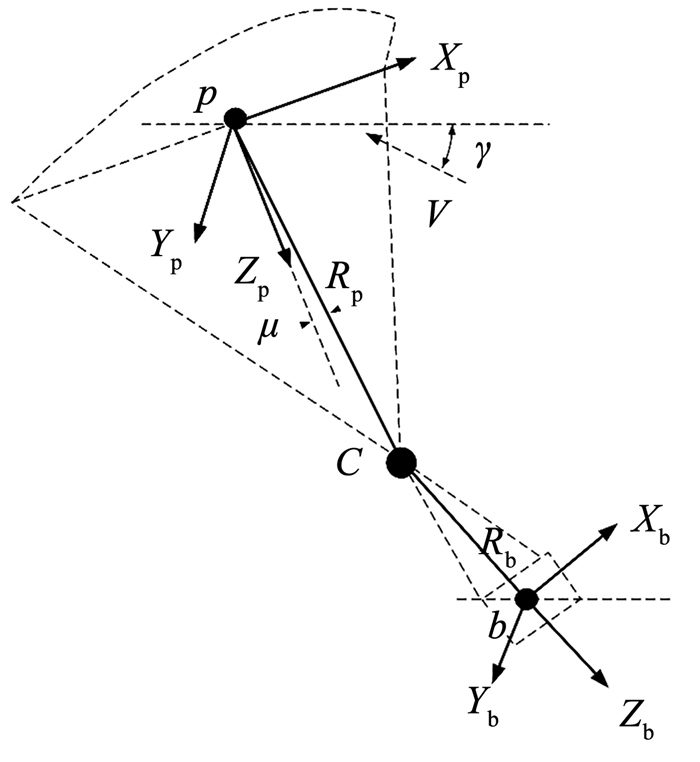 图 2 翼伞结构示意 Fig. 2 Schematic diagram of parafoil structure
 1.3 气动力模型雀降操纵会引起翼伞气动外形改变,从而使翼伞气动特性发生改变,因此气动力系数和气动力矩系数计算过程中需加入双侧操纵量的影响,计算公式如下:
$\left\{\begin{array}{l}\mathrm{C}_{L}=\mathrm{C}_{L}\left(\alpha_{p}, \delta_{e}\right) \\\mathrm{C}_{D}^{p}=\mathrm{C}_{D}^{p}\left(\alpha_{p}, \delta_{e}\right)\end{array}\right.$
$\begin{align*}& \left\{\begin{array}{l}C_{X}=\left(-C_{\mathrm{D}}^{\mathrm{p}} u_{\mathrm{p}}+C_{\mathrm{L}} w_{\mathrm{p}}\right) / V_{\mathrm{p}} \\C_{Y}=C_{Y_{\beta}} \beta+C_{Y_{r}}\left(r_{\mathrm{p}} b / 2 V_{\mathrm{p}}\right) \\C_{Z}=\left(-C_{\mathrm{D}}^{\mathrm{p}} w_{\mathrm{p}}-C_{\mathrm{L}} u_{\mathrm{p}}\right) / V_{\mathrm{p}}\end{array}\right. \\& \left\{\begin{array}{l}C_{l}=C_{l_{\beta}} \beta+C_{l_{p}} \frac{p_{\mathrm{p}} b}{2 V_{\mathrm{p}}}+C_{l_{r}} \frac{r_{\mathrm{p}} b}{2 V_{\mathrm{p}}} \\C_{m}=C_{m c / 4}\left(\alpha_{\mathrm{p}}, \delta_{\mathrm{e}}\right)+C_{m_{q}} \frac{p_{\mathrm{p}} c}{2 V_{\mathrm{p}}} \\C_{n}=C_{n_{\beta}} \beta+C_{n_{\mathrm{p}}} \frac{p_{\mathrm{p}} b}{2 V_{\mathrm{p}}}+C_{n_{r}} \frac{r_{\mathrm{p}} b}{2 V_{\mathrm{p}} b}\end{array}\right. \end{align*}$ (8)
式中:δe为双侧下偏量,CX、CY、CZ为翼伞体轴坐标系下的气动力系数,Cl、Cm、Cn为翼伞的滚转、俯仰、偏航力矩系数,CL、CpD、Cmc/4为采用插值拟合法拟合得到和攻角、双侧下偏量同时相关的升力、阻力、1/4弦线处俯仰力矩系数,其他气动数据取值为常数。
2 翼伞系统动力学仿真 2.1 研究对象及计算工况为验证本文模型及方法的准确性,以文献[19]中翼伞系统为研究对象采用龙格库塔方法进行了编程计算。其中,翼伞系统结构参数见表 1,翼伞、翼载荷质量分别为5、135 kg,式(7)中的气动参数和文献[19]一致,初始运动参数见表 2。为更好模拟雀降操纵,本文设计如下仿真工况:在5 s时对翼伞施加双侧下拉操纵,操纵下偏量为100%,30 s时操纵下偏量回复至0,操纵实施时间均为1 s,计算总时长60 s。
表 1
7.5 3.75 0.675 9
伞衣面积Sp/m2 载荷体阻力面积Sb/m2 翼伞中心与系统质心距离Rp/m 载荷中心与系统质心距离Rb/m
28 0.5 -7.5 0.5
表 1 翼伞系统结构参数 Tab. 1 Parafoi-payload system structure parameters
表 2
10.5, 0, 3.5 0, -10, 0 0, 0, -1 000
表 2 初始运动状态参数 Tab. 2 Initial motion parameters
2.2 结果分析翼伞速度和伞载姿态的动态变化如图 3所示。由图 3可知,本文的仿真结果与文献结果规律一致,翼伞的运动特性变化与操纵绳下拉相互对应,翼伞系统工作过程分为无操纵稳定滑翔阶段、双侧全下拉减速雀降阶段、操纵绳回复至稳定滑翔3个阶段。
Fig. 3
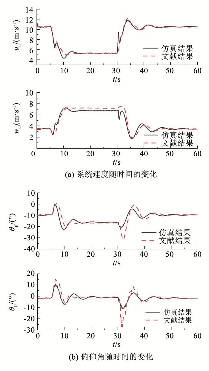 图 3 模型和文献结果对比 Fig. 3 Comparison between model and literature results
 操纵绳在第5 s下拉后,翼伞的升力、阻力、俯仰力矩系数均增加,从而导致翼伞的前向速度和垂相速度减小,俯仰角增加,翼伞垂向速度在第6 s达到最小值,该值被称作最优着陆速度,此时被认为是雀降操纵的最佳着陆点,也是确定最优雀降高度的依据;之后由于翼伞的攻角急速增加,升力系数减小,翼伞的垂向速度逐渐增加,俯仰力矩系数逐渐减小从而俯仰角减小。操纵绳在第30 s恢复后,翼伞的升力系数增加,阻力、俯仰力矩系数减小,从而导致翼伞的前向速度增加、垂相速度减小、俯仰角减小,之后由于俯仰力矩系数增加,俯仰角增加,最终恢复至初始值。
表 3为稳定时各阶段运动特征量和文献的对比,最大误差为8.20%。上述结果验证了本文雀降操纵两体动力学模型的准确性。
表 3
滑翔阶段/s
(0~5, 50~60) 文献 10.50 3.50 3.00
本文 10.52 3.53 2.98
误差/% 0.20 0.90 0.70
雀降阶段/s
(20~30) 文献 5.25 7.20 0.73
本文 5.31 6.75 0.79
误差/% 1.10 6.30 8.20
表 3 本文和文献系统稳定运动特性对比 Tab. 3 Comparison of main steady flight characteristics between present study and literature
3 雀降操纵优化高度确定方法 3.1 优化目标及求解方法根据翼伞系统动力学仿真的分析结果,雀降操纵后系统的垂直速度会迅速降低到最小值随后增加,为保证着陆安全,应该确保翼伞系统以载荷体最小垂直速度着陆。本文以载荷体垂直着陆速度最小为优化目标,采用时间二分法获得最优雀降实施高度,技术方案如图 4所示,若载荷体垂直速度达到最小时的高度和预设着陆高度之间差值的误差小于0.01 m则可认为符合优化目标。
Fig. 4
 图 4 雀降实施高度优化方案 Fig. 4 Optimization scheme of flare altitude
 翼伞雀降采用一次操纵、“匀速下拉”模式[20],操纵总时长为3 s,操纵量变化满足:
$\begin{equation*}\delta_{s}=\frac{t-t_{k}}{3}, \quad t_{k} \leqslant t \leqslant t_{k}+3 \end{equation*}$ (9)
3.2 雀降操纵实施高度影响分析为探究翼伞系统滑翔运动状态对雀降实施高度的影响,本文以翼伞系统为对象,设计了10种计算工况,采用稳定滑翔阶段初始工况作为稳定状态计算工况,同时设计初始非稳定状态,具体见表 4。
表 4
uc, vc, wc/(m·s-1) ?p, θp, φp/(°) H0/km
1 (5.0, 0, 8.0) (0, 0, 0) 1~ 5 非稳定滑翔状态
2 (10.5, 0, 3.5) (0, -10, 0) 1~ 5 稳定滑翔状态
表 4 仿真内容 Tab. 4 Simulation content
通过计算得到了最优雀降实施高度随不同初始高度H0的变化情况如图 5所示。随着高度的变化,初始稳定工况和非稳定工况的雀降高度集中在7.02 m左右;同时仿真结果中不同初始工况下的雀降时长、着陆速度均相同,分别为2.63 s、1.95 m/s。对同一对象无外在干扰的情况下,不同的初始运动参数最终会稳定至同一滑翔状态,本文由于算法的影响,不同初始工况下的雀降高度存在较小的波动,平均保持在7.02 m左右。
Fig. 5
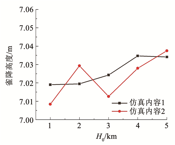 图 5 不同初始参数下雀降高度随初始高度的变化曲线 Fig. 5 Curve of flare altitude with initial altitude for different initial parameters
 假设翼伞系统雀降操纵前处于稳定滑翔状态,初始高度为1 km开始计时,若雀降提前实施或延迟实施3 m,操纵时刻虽然相差不大但着陆速度却相差较大(如表 5及图 6所示)。由此可知,雀降操纵时机对着陆速度的影响较大,需合理判断雀降实施高度以更好地保证载荷体的无损着陆。
表 5
提前实施 10.01 278.69 4.18
准确实施 7.01 279.56 1.95
延迟实施 4.01 280.42 2.67
表 5 不同雀降实施高度下的比较 Tab. 5 Comparison of different flare altitudes
Fig. 6
 图 6 载荷体垂直高度随垂直速度的变化 Fig. 6 Variation of altitude of payload with vertical velocity
 4 雀降操纵影响因素研究 4.1 翼载荷影响为探究翼载荷mb对雀降操纵的影响,设置翼载荷分别为55~215 kg的5组对比工况,初始工况见表 2,得到结果如图 7所示。
Fig. 7
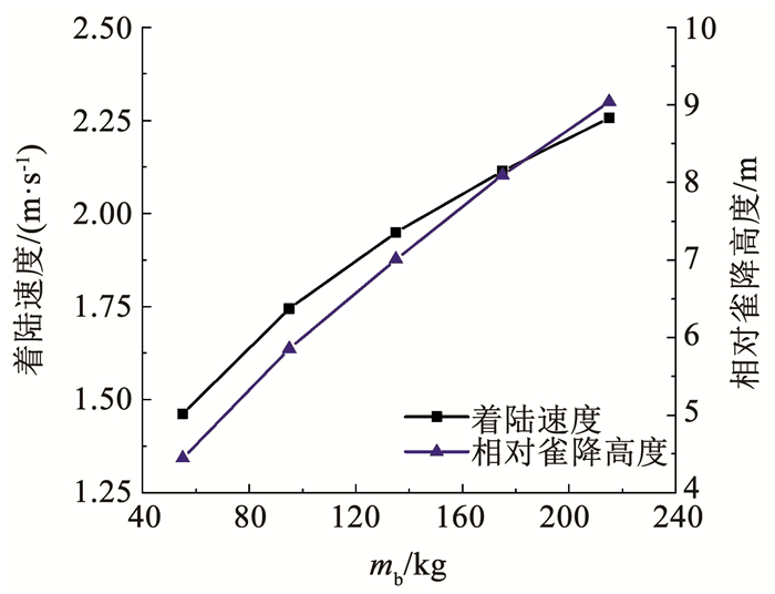 图 7 翼载荷对雀降操纵的影响 Fig. 7 Influence of wing load on flare control
 随着翼载荷的增加,滑翔速度增加,雀降操纵时的高度损失增加,因此需要在更高的高度实施雀降操纵,相对雀降高度随之增加(如图 7所示),且相对雀降高度与翼载荷的1/2次方成正比,采用最小二乘法进行拟合,得到如式(10)所示的计算模型;当翼载荷越大时,系统重力越大,即翼伞竖直向上的气动力越大,着陆速度增加,且着陆速度与翼载荷的1/3次方成正比,采用最小二乘法进行拟合,得到如式(11)所示的计算模型。
$ h_{\text {land }}=0.6181 m_{\mathrm{b}}^{1 / 2}, R^{2}=0.998 $ (10)
$w_{\text {land }}=0.3784 m_{\mathrm{b}}^{1 / 3}, R^{2}=0.998 $ (11)
为验证相对雀降高度和着陆速度模型的准确性和适用性,本文选取大(250 kg)、中(100 kg)、小(20 kg) 翼载荷进行雀降数值计算,所得到的结果与式(10)、(11)计算结果进行对比,结果如表 6及图 8所示。从图 8中可以看出,本文提出的相对雀降高度和着陆速度计算模型与仿真计算结果较为符合,最大误差小于4.00%,表明该模型在全翼载荷范围内均有良好的适用性。
表 6
计算模型 仿真计算 误差/% 计算模型 仿真计算 误差/%
250 9.85 9.77 -0.73 2.37 2.39 0.85
100 5.99 6.18 3.14 1.77 1.76 -0.66
20 2.87 2.76 -3.73 1.06 1.03 -2.38
表 6 计算模型和数值计算结果对比 Tab. 6 Comparison of calculation models and numerical calculation results
Fig. 8
 图 8 不同翼载荷下计算模型和数值计算结果对比 Fig. 8 Comparison of calculation models and numerical calculation results under different wing loads
 4.2 着陆高度影响考虑到空气密度的变化,设置5组不同着陆高度(0~4 km)完成着陆高度对雀降性能的影响,仿真初始高度为5 km,初始运动参数见表 2,得到翼伞系统相对雀降高度和着陆速度变化如图 9所示。
Fig. 9
 图 9 着陆高度对雀降操纵的影响 Fig. 9 Influence of landing altitude on flare control
 随着着陆高度减小,空气密度增大,近地面的滑翔速度减小,因此雀降操纵时的高度损失减小,雀降实施高度减小;同时由于越小的着陆海拔高度雀降操纵前滑翔速度越小,操纵后着陆速度越小。分析得到相对雀降高度、着陆速度分别和密度的-1/2、-1/3次方成正比,计算模型如式(12)、(13)所示。
$h_{\text {land }}=7.8590 \rho^{-1 / 2}, R^{2}=0.987 $ (12)
$w_{\text {land }}=2.0800 \rho^{-1 / 3}, R^{2}=0.999 $ (13)
选取大(4.5 km)、中(1.5 km)、小(-0.2 km)着陆高度所对应的密度进行雀降数值计算,所得到的结果对比如表 7及图 10所示。从图 10中可以看出,本文提出的相对雀降高度和着陆速度计算模型与仿真计算结果最大误差小于2.00%,表明该模型在全着陆高度范围内均有良好的适用性。
表 7
计算模型 仿真计算 误差/% 计算模型 仿真计算 误差/%
4.5 0.78 9.06 8.92 -1.60 2.26 2.26 0.28
1.5 1.06 7.60 7.64 0.45 2.04 2.04 -0.10
-0.2 1.25 6.92 7.03 1.63 1.94 1.93 -0.28
表 7 计算模型和数值计算结果对比 Tab. 7 Comparison of calculation models and numerical calculation results
Fig. 10
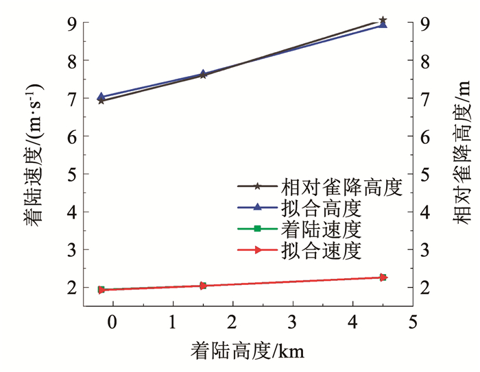 图 10 不同着陆高度下计算模型和数值计算结果对比 Fig. 10 Comparison of calculation models and numerical calculation results under different landing altitudes
 4.3 安装角影响翼伞安装角是定位翼伞相对于载荷体位置的重要参数,工程中其大小可通过改变伞绳长度来调节。采用初始工况见表 2,通过仿真计算得到不同安装角下翼伞系统着陆速度、相对雀降高度的变化如图 11所示,高度随攻角和气动力的变化曲线如图 12、13所示。
Fig. 11
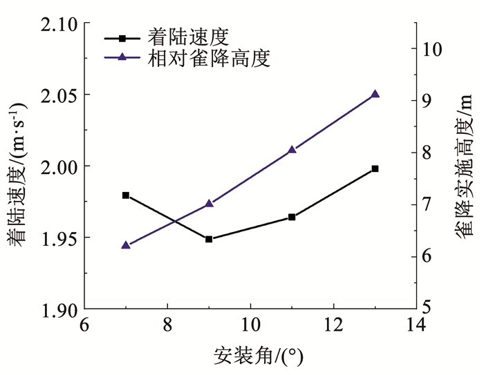 图 11 安装角对雀降操纵的影响 Fig. 11 Influence of attack angle on flare control
 Fig. 12
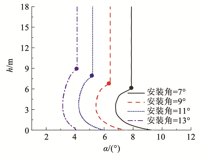 图 12 系统高度随攻角变化曲线 Fig. 12 Curve of system altitude variation with angle of attack
 Fig. 13
 图 13 系统高度随翼伞竖直气动力的变化曲线 Fig. 13 Curve of system altitude variation with vertical aerodynamic force
 随着安装角的增加,稳定滑翔阶段平衡攻角减小(如图 12所示),从而引起翼伞气动特性改变,升、阻力系数减小,由升、阻力计算公式及系统平衡可知稳定阶段滑翔速度增大,同理可知雀降实施操纵提前,相对雀降高度增加(如图 11所示),且相对雀降高度与平衡攻角的-1/2次方成正比,得到如式(14)所示的计算模型。雀降操纵后,不同安装角下气动力变化幅度接近(如图 13所示),着陆速度随安装角的增加先减小后增加,在此范围内差值小于0.1 m/s,几乎可以忽略不计。
$\begin{equation*}h_{\text {land }}=17.8000 \alpha^{-1 / 2}, R^{2}=0.983 \end{equation*}$ (14)
选取大(15°)、中(10°)、小(5°)安装角进行雀降数值计算,所得到的结果对比如表 8及图 14所示。从图 14中可以看出,该计算模型与数值计算结果较为符合,最大误差小于4.00%,表明该模型在全安装角范围内均有良好的适用性。
表 8
计算模型 仿真计算 误差/%
15 3.15 9.98 10.04 0.60
10 5.77 7.49 7.41 -1.08
5 9.97 5.43 5.64 3.87
表 8 计算模型和数值计算结果对比 Tab. 8 Comparison of calculation models and numerical calculation results
Fig. 14
 图 14 不同安装角下计算模型和数值计算结果对比 Fig. 14 Comparison of calculation models and numerical calculation results under different attack angles
 5 结论1) 翼伞系统雀降高度需准确实施,提前或延迟实施均会引起着陆速度的增加。
2) 初始运动参数对最优雀降高度和着陆速度几乎没有影响;随着翼载荷和着陆高度的增加,系统雀降实施高度和着陆速度增加,安全性降低;随着安装角的增加,雀降实施高度增加。
3) 相对雀降高度及着陆速度的拟合计算模型结果和仿真结果最大误差小于4.00%,计算模型具有良好的适用性。
参考文献
[1] 赵秋艳. 翼伞雀降技术[J]. 航天返回与遥感, 1999, 20(2): 5.
ZHAO Qiuyan. Flare maneuver of RAM-AIR parachute[J]. Spacecraft Recovery & Remote Sensing, 1999, 20(2): 5.
[2] 王利荣. 降落伞理论与应用[M]. 北京: 宇航出版社, 1997.
WANG Lirong. Parachute theory and application[M]. Beijing: Aerospace Press, 1997.
[3] 赵培尧. 单层翼伞回收末段飞行特性研究[D]. 北京: 北京理工大学, 2017
ZHAO Peiyao. Study on the flight characteristics of parawing at the last stage of recycling[D]. Beijing: Beijing University of Technology, 2017
[4] 余莉. 气动减速技术[M]. 北京: 科学出版社, 2018.
YU Li. Aerodynamic deceleration technology[M]. Beijing: Science Press, 2018.
[5] SLEGERS N, GORMAN C. Comparison and analysis of multi-body parafoil models with varying degrees of freedom[C]//21st AIAA Aerodynamic Decelerator Systems Technology Conference and Seminar. Reston: AIAA, 2011: AIAA2011-2615. DOI: 10.2514/6.2011-2615
[6] TAN Panlong, SUN Mingwei, SUN Qinglin, et al. Dynamic modeling and experimental verification of powered parafoil with two suspending points[J]. IEEE Access, 2020, 8: 12955. DOI:10.1109/ACCESS.2020.2965541
[7] GOODRICK T. Simulation studies of the flight dynamics of gliding parachute systems[C]//6th Aerodynamic Decelerator and Balloon Technology Conference. Reston: AIAA, 1979: 417. DOI: 10.2514/6.1979-417
[8] GOODRICK T. Comparison of simulation and experimental data for a gliding parachute in dynamic flight[C]//7th Aerodynamic Decelerator and Balloon Technology Conference. Reston: AIAA, 1981: 1924. DOI: 10.2514/6.1981-1924.
[9] 卞琨. 复杂风场下翼伞系统航迹规划与跟踪控制[D]. 长沙: 国防科技大学, 2020
BIAN Kun. Trajectory planning and path following control of parafoil system in complex wind area[D]. Changsha: National University of Defense Technology, 2020. DOI: 10.27052/d.cnki.gzjgu.2020.000183
[10] 胡容. 高空精确空投翼伞归航轨迹规划与控制[D]. 南京: 南京航空航天大学, 2014
HU Rong. Homing trajectory planning and control for the accurate aerial delivery of parafoil system[D]. Nanjing: Nanjing University of Aeronautics and Astronautics, 2014
[11] 张兴会, 朱二琳. 翼伞系统雀降性能及控制研究[J]. 航天控制, 2012, 30(1): 29.
ZHANG Xinghui, ZHU Erlin. The study of the flare-landing performance and control of parafoil system[J]. Aerospace Control, 2012, 30(1): 29. DOI:10.16804/j.cnki.issn1006-3242.2012.01.007
[12] 熊菁. 翼伞系统动力学与归航方案研究[D]. 长沙: 国防科学技术大学, 2005
XIONG Jing. Research on the dynamics and homing project of parafoil system[D]. Changsha: National University of Defense Science and Technology, 2005
[13] OCHI Y. Modeling and simulation of flight dynamics of a relative-roll-type parafoil[C]//AIAA Scitech 2020 Forum. Reston: AIAA, 2020: 1643. DOI: 10.2514/6.2020-1643
[14] GANG Yu. Nine-degree of freedom modeling and flight dynamic analysis of parafoil aerial delivery system[J]. Procedia Engineering, 2015, 99: 866. DOI:10.1016/j.proeng.2014.12.614
[15] SLEGERS N, COSTELLO M. Aspects of control for aparafoil and payload system[J]. Journal of Guidance, Control, and Dynamics, 2003, 26(6): 898. DOI:10.2514/2.6933
[16] MORIYOSHI T, YAMADA K, NISHIDA H. The effect of rigging angle on longitudinal direction motion ofparafoil-type vehicle: basic stability analysis and wind tunnel test[J]. International Journal of Aerospace Engineering, 2020, 2020: 8861714. DOI:10.1155/2020/8861714
[17] 杨华, 宋磊, 王文剑, 等. 动力翼伞纵向四自由度动力学仿真[J]. 北京航空航天大学学报, 2014, 40(11): 1615.
YANG Hua, SONG Lei, WANG Wenjian, et al. 4-DOF longitudinal dynamic simulation of powered-parafoil[J]. Journal of Beijing University of Aeronautics and Astronautics, 2014, 40(11): 1615. DOI:10.13700/j.bh.1001-5965.2014.0086
[18] 李东. 区域信标/差分GPS组网导航技术研究[D]. 西安: 西北工业大学, 2001
LI Dong. Research onRB/DGPS-network based integrated navigation technology[D]. Xi'an: Northwestern Polytechnical University, 2001
[19] PRAKASH O, ANANTHKRISHNAN N. Modeling and simulation of 9-DOFparafoil-payload system flight dynamics[C]//AIAA Atmospheric Flight Mechanics Conference and Exhibit. Reston: AIAA, 2006: 6130. DOI: 10.2514/6.2006-6130
[20] 程杨, 仇博文, 余莉, 等. 操纵方式对翼伞系统雀降性能的影响研究[J/OL]. 北京航空航天大学学报. https://doi.org/10.13700/j.bh.1001-5965.2022.0914
CHENG Yang, QIU Bowen, YU Li, et al. The effects of maneuver modes on the flare performance of parafoil-payload system flare performance[J/OL]. Journal of Beijing University of Aeronautics and Astronautics. https://doi.org/10.13700/j.bh.1001-5965.2022.0914
