张赛军,张首冠,张昆,周驰
(华南理工大学 机械与汽车工程学院,广州 510640)
摘要:
为研究高强钢板材在冷成形下的损伤演化与韧性断裂行为,将DF2012韧性断裂准则修正为初始损伤判据,同时参考连续损伤力学理论引入损伤变量D以衡量材料的累积损伤,并将其耦合到塑性模型中,构建了一种半耦合韧性断裂准则。以TRIP780高强钢板为研究对象,针对不同应力状态设计了6种形状的试样,借助电阻损伤测量法与DIC数字图像法进行了力学性能试验并测定初始损伤位移。采用非相关流动准则(NAFR)的Drucker各向异性屈服函数和Swift-Voce硬化模型准确描述了材料的塑性变形过程,然后分别利用试验模拟混合法和逆向工程法对初始损伤模型和损伤演化参数进行了标定。使用Fortran语言将构建的本构模型与损伤演化模型编译为VUMAT子程序并嵌入ABAQUS/Explicit模块中进行断裂模拟预测,并与未耦合损伤模型进行比较。结果表明:构建的半耦合韧性断裂准则能够准确描述TRIP780板材在不同应力状态下变形后期的损伤诱导软化行为,预测的断裂位移最大相对误差仅为1.31%。相较于常用的非耦合断裂模型,所提模型针对具有软化效应的高强钢表现出明显的优越性,适合用于高强钢板冷冲压成形的破裂预测中。
关键词: 半耦合韧性断裂准则 本构模型 损伤诱导软化 TRIP780 板材成形
DOI:10.11918/202206014
分类号:O346.1;TG142.1
文献标识码:A
基金项目:广东省自然科学基金(2021A1515010598)
A semi-coupled ductile fracture criterion and its application on TRIP780high-strength steel sheet
ZHANG Saijun,ZHANG Shouguan,ZHANG Kun,ZHOU Chi
(School of Mechanical and Automotive Engineering, South China University of Technology, Guangzhou 510640, China)
Abstract:
To study the damage evolution and ductile fracture behavior of high-strength steel sheet under cold forming, we proposed a semi-coupled ductile fracture criterion. The DF2012 ductile fracture criterion was modified as the initial damage criterion. On the basis of the continuum damage mechanics (CDM) theory, the damage variable D was introduced to measure the cumulative damage of the material, and was coupled to the plasticity model. Taking TRIP780 high-strength steel as research object, six types of specimens were designed for different stress states. The resistance damage measurement and DIC digital image method were utilized to test the mechanical properties and initial damage displacement of specimens. The Drucker anisotropic yield function with non-associated flow rule (NAFR) and the Swift-Voce hardening model were used to accurately describe the plastic deformation process of the material. The initial damage model and the damage evolution parameters were calibrated by the hybrid test-simulation method and the inverse engineering method respectively. The constructed constitutive model and damage evolution model were compiled into the VUMAT subroutine using Fortran and implemented in the ABAQUS/Explicit module for fracture prediction, which were then compared with uncoupled damage model. Results show that the constructed semi-coupled ductile fracture criterion could accurately predict the damage-induced softening of TRIP780 sheets under different stress states. The maximum relative error of predicted damage displacement was only 1.31%. Compared with the commonly used uncoupled fracture model, the proposed model showed obvious superiority for high-strength steel with softening effect, which is suitable for fracture prediction in cold stamping forming of high-strength steel sheets.
Key words: semi-coupled ductile fracture criterion constitutive model damage-induced softening TRIP780 sheet forming
张赛军, 张首冠, 张昆, 周驰. 一种半耦合韧性断裂准则及其在TRIP780中的应用[J]. 哈尔滨工业大学学报, 2023, 55(1): 89-97. DOI: 10.11918/202206014.

ZHANG Saijun, ZHANG Shouguan, ZHANG Kun, ZHOU Chi. A semi-coupled ductile fracture criterion and its application on TRIP780 high-strength steel sheet[J]. Journal of Harbin Institute of Technology, 2023, 55(1): 89-97. DOI: 10.11918/202206014.

基金项目 广东省自然科学基金(2021A1515010598) 作者简介 张赛军(1978—),男,副教授,硕士生导师 通信作者 张赛军,mesjzhang@scut.edu.cn 文章历史 收稿日期: 2022-06-02
Abstract Full text Figures/Tables PDF
一种半耦合韧性断裂准则及其在TRIP780中的应用
张赛军

 , 张首冠, 张昆, 周驰
 华南理工大学 机械与汽车工程学院, 广州 510640
收稿日期: 2022-06-02; 接受日期: 2022-07-25; 网络出版日期: 2022-10-24
基金项目: 广东省自然科学基金(2021A1515010598)
作者简介: 张赛军(1978—),男,副教授,硕士生导师
通信作者: 张赛军,mesjzhang@scut.edu.cn
摘要: 为研究高强钢板材在冷成形下的损伤演化与韧性断裂行为,将DF2012韧性断裂准则修正为初始损伤判据,同时参考连续损伤力学理论引入损伤变量D以衡量材料的累积损伤,并将其耦合到塑性模型中,构建了一种半耦合韧性断裂准则。以TRIP780高强钢板为研究对象,针对不同应力状态设计了6种形状的试样,借助电阻损伤测量法与DIC数字图像法进行了力学性能试验并测定初始损伤位移。采用非相关流动准则(NAFR)的Drucker各向异性屈服函数和Swift-Voce硬化模型准确描述了材料的塑性变形过程,然后分别利用试验模拟混合法和逆向工程法对初始损伤模型和损伤演化参数进行了标定。使用Fortran语言将构建的本构模型与损伤演化模型编译为VUMAT子程序并嵌入ABAQUS/Explicit模块中进行断裂模拟预测,并与未耦合损伤模型进行比较。结果表明:构建的半耦合韧性断裂准则能够准确描述TRIP780板材在不同应力状态下变形后期的损伤诱导软化行为,预测的断裂位移最大相对误差仅为1.31%。相较于常用的非耦合断裂模型,所提模型针对具有软化效应的高强钢表现出明显的优越性,适合用于高强钢板冷冲压成形的破裂预测中。
关键词: 半耦合韧性断裂准则 本构模型 损伤诱导软化 TRIP780 板材成形
A semi-coupled ductile fracture criterion and its application on TRIP780 high-strength steel sheet
ZHANG Saijun

 , ZHANG Shouguan, ZHANG Kun, ZHOU Chi
 School of Mechanical and Automotive Engineering, South China University of Technology, Guangzhou 510640, China
Abstract: To study the damage evolution and ductile fracture behavior of high-strength steel sheet under cold forming, we proposed a semi-coupled ductile fracture criterion. The DF2012 ductile fracture criterion was modified as the initial damage criterion. On the basis of the continuum damage mechanics (CDM) theory, the damage variable D was introduced to measure the cumulative damage of the material, and was coupled to the plasticity model. Taking TRIP780 high-strength steel as research object, six types of specimens were designed for different stress states. The resistance damage measurement and DIC digital image method were utilized to test the mechanical properties and initial damage displacement of specimens. The Drucker anisotropic yield function with non-associated flow rule (NAFR) and the Swift-Voce hardening model were used to accurately describe the plastic deformation process of the material. The initial damage model and the damage evolution parameters were calibrated by the hybrid test-simulation method and the inverse engineering method respectively. The constructed constitutive model and damage evolution model were compiled into the VUMAT subroutine using Fortran and implemented in the ABAQUS/Explicit module for fracture prediction, which were then compared with uncoupled damage model. Results show that the constructed semi-coupled ductile fracture criterion could accurately predict the damage-induced softening of TRIP780 sheets under different stress states. The maximum relative error of predicted damage displacement was only 1.31%. Compared with the commonly used uncoupled fracture model, the proposed model showed obvious superiority for high-strength steel with softening effect, which is suitable for fracture prediction in cold stamping forming of high-strength steel sheets.
Keywords: semi-coupled ductile fracture criterion constitutive model damage-induced softening TRIP780 sheet forming
高强钢是汽车车身中常用的轻量化材料之一[1],能够有效减轻车身质量,进而节约能源并降低排放[2]。相变诱发塑性(transformation-induced plasticity, TRIP)钢在变形过程中,应变诱发残余奥氏体相变致使相变强化与塑性增长[3],通过特殊的热处理后TRIP钢可以兼顾高抗拉强度与良好的延展性,因此在车身结构件和辅助零件中都有应用[4-5]。破裂缺陷是板材成形中常见的失效形式,也是高强钢在车身结构应用中的主要问题之一,研究其韧性断裂并为实际成形提供指导,对高强钢在汽车结构中的广泛应用有着重要意义。
金属材料在成形过程中经历塑性变形阶段后的断裂行为称为韧性断裂。韧性断裂准则作为最常用的断裂预测方法,在函数表达上更加灵活,能针对不同材料在更广泛的变形条件下进行破裂预测。韧性断裂准则可以分为耦合与非耦合两大类。耦合韧性断裂准则将材料内部损伤考虑在内,其典型代表分别为Kachanov[6]、Lemaitre[7-8]和Chaboche[9-11]等提出并改进完善的连续损伤力学CDM模型和Gurson[12]与Tvergaard等[13-15]提出并改进的GTN模型,形式复杂。非耦合韧性断裂准则忽略损伤累积的影响,直接给出判定材料破裂的临界应变,传统的Cockcroft-Latham[16]、Oh[17]、McClintock[18]、Rice-Tracey[19]等模型均有一定应用。近年来,Bai等[20]和Lou等[21]引入罗德参数分别提出了著名的MMC与DF2012模型。DF2012及其扩展而来的Lou系列模型[22-23]基于微观孔洞形核、长大和聚结机制描述断裂,已经广泛应用于镁铝合金和高强钢等金属材料的断裂预测[24-25]。此外,也有学者提出新的断裂模型以预测不同变形机制下材料的韧性断裂[26-27]。
非耦合断裂准则与耦合断裂准则各有其优缺点。针对材料变形后期的软化行为,Li等[28]通过定义材料的软化规律和损伤增量演化规律,首次提出半耦合韧性断裂准则的概念。类似地,Lian等[29]强调了裂纹萌生这一概念,将其与材料的破裂区分开来,定义材料的破裂为材料停止提供正常力学性能时的宏观行为,当裂纹萌生时,材料的承载能力将发生一定的弱化现象。在具有明显软化现象的高强钢中,半耦合韧性断裂准则已经得到一定程度的应用,并显示出相较非耦合断裂准则的优越性。Lian模型针对DP600高强钢和S355J2+N钢材的破裂预测均获得了较高的精度; Münstermann等[30]基于该模型研究了DP600与DP1000高强钢的裂纹萌生规律; 近年来,Liu等[31]和Zhang等[32]分别对损伤增量的表达形式进行改进,均取得了一定的预测精度。目前半耦合韧性断裂准则的研究应用不多,主要问题是模型标定较复杂,同时涉及宽应力状态范围的预测精度尚有待提高,但对于变形后期具有明显软化效应的钢材的损伤断裂研究具有优越性。
本文将应力三轴度以-1/3截止值的形式引入损伤增量模型,构建了一种半耦合韧性断裂准则。以TRIP780高强钢为研究对象,基于电阻损伤测定法与DIC数字图像法进行力学试验,采用非相关流动准则Drucker各向异性屈服函数与Swift-Voce硬化模型描述了材料的各向异性力学行为。将DF2012模型修正为初始损伤判据,分别运用试验模拟混合法和逆向工程法对初始损伤模型和损伤演化参数进行了标定,并于ABAQUS/Explicit中进行断裂预测模拟。
1 试验研究 1.1 试验材料和试样制备以厚度为1.2 mm的TRIP780钢板作为试验材料,所用6种试样尺寸见图 1。
Fig. 1
 图 1 试样尺寸(mm) Fig. 1 Dimensions of specimens(mm)
 其中,狗骨试样用于确定材料的力学性能,其余试样表征从纯剪切至平面应变的应力状态,用于研究材料不同应力状态下的韧性断裂行为。所有试样参照标准GB/T 2975—2018《钢及钢产品力学性能试验取样位置及试样制备》进行制备。为保证试验的可靠性,使用精度为0.01 mm的线切割机慢走丝加工,所有试样均切割自同一块板材,同时将每种试样分别沿轧制方向0° (RD)、45° (DD)、90° (TD)制备以研究其塑性各向异性。
1.2 试验过程为了确定试样在拉伸过程中的损伤初始位置,参考Münstermann等[33]的方法测定初始损伤时刻。如图 2所示,利用直流电阻测试仪测量试样在拉伸过程中每一时刻两端之间的电阻值,当试样内部出现孔洞或微小裂纹时,试样的有效横截面积减小,电阻的变化趋势将会突然改变,以此点作为材料发生初始损伤的时刻。为避免电流对万能试验机造成破坏,在试样的夹持部分添加绝缘电阻片。所有试样均在同一台岛津AG-X Plus 100 kN万能试验机进行试验,拉伸速度设置为1 mm/min,每组试验均重复3次。试验中的变形过程由Basler工业相机等时间间隔拍摄记录,频率为10 Hz。使用DIC数字图像处理法计算试样的全场应变与局部应变。初始损伤点的测定需要对试验数据进行线性拟合,以圆孔试样为例,初始损伤点的确定见图 3。
Fig. 2
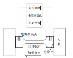 图 2 电阻损伤法示意 Fig. 2 Schematic of resistance damage method
 Fig. 3
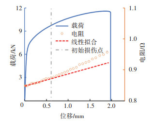 图 3 初始损伤点确定 Fig. 3 Determination of initial damage point
 2 本构模型 2.1 Drucker各向异性屈服函数使用准确的本构模型描述材料的塑性行为是断裂预测的关键条件。本构模型可以分为屈服函数与硬化模型两部分。为了描述材料的各向异性力学行为,选用各向异性屈服函数确定材料的屈服面是最常用的方法。Drucker[34]在Mises屈服函数的基础上引入了第三应力不变量,Lou等[35]将其扩展为各向异性的形式,其表达式如下:
$\bar{\sigma}=\left(J_2^{\prime 3}-c J_3^{\prime 2}\right)^{1 / 6}$ (1)
式中:c为经验常数,BCC金属取1.226,FCC金属取2;J2′和J3′是应力张量s′的第二和第三应力不变量,在平面应力条件下,形式如下:
$J_2^{\prime}=\frac{1}{2} \boldsymbol{s}^{\prime}: \boldsymbol{s}^{\prime}=-s_{11}^{\prime} s_{22}^{\prime}-s_{22}^{\prime} s_{33}^{\prime}-s_{11}^{\prime} s_{33}^{\prime}+s_{12}^{\prime 2}$ (&)
$J_3^{\prime}=\operatorname{det} \boldsymbol{s}^{\prime}=-s_{11}^{\prime} s_{22}^{\prime} s_{33}^{\prime}-s_{33}^{\prime} s_{12}^{\prime 2}$ (3)
进行线性变化后的应力张量s′形式如下:
$\boldsymbol{s}^{\prime} \equiv\left[\begin{array}{l}s_{11}^{\prime} \\s_{22}^{\prime} \\s_{33}^{\prime} \\s_{12}^{\prime}\end{array}\right]=\left[\begin{array}{ccc}\left(c_2^{\prime}+c_3^{\prime}\right) / 3 & -c_3^{\prime} / 3 & 0 \\-c_3^{\prime} / 3 & \left(c_3^{\prime}+c_1^{\prime}\right) / 3 & 0 \\-c_2^{\prime} / 3 & -c_1^{\prime} / 3 & 0 \\0 & 0 & c_4^{\prime}\end{array}\right]\left[\begin{array}{l}\sigma_{x x} \\\sigma_{y y} \\\sigma_{x y}\end{array}\right]$ (4)
式中c1′、c2′、c3′和c4′为表征材料各向异性的参数。
借助试验获取材料0°、45°和90°方向的初始屈服应力,等双向拉伸状态下的屈服应力σb和厚向异性系数rb可使用理论公式σb=(σ0+2σ45+σ90)/4与rb=(r0+2r45+r90)/4获取。本研究使用非相关流动准则的Drucker屈服函数,标定参数见表 1。分别用屈服应力σ与厚向异性系数r对Drucker屈服函数进行标定,表示为Drucker_σ和Drucker_r。
表 1
Drucker_σ 1.710 1.819 1.762 1.768 1.226
Drucker_r 1.675 1.732 1.644 1.619 1.226
表 1 Drucker屈服函数的标定结果 Tab. 1 Calibration of Drucker yield functions
利用表 1得到的标定参数,将2个屈服函数预测TRIP780的屈服应力及r值与试验值对比,见图 4。可以看出非相关流动准则Drucker屈服函数无论是在屈服应力还是r值的预测上都有较高的吻合度,适合用于描述材料的各向异性屈服行为。
Fig. 4
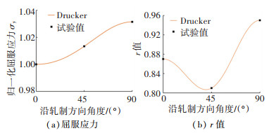 图 4 Drucker屈服函数的预测结果 Fig. 4 Prediction results of Drucker yield functions
 2.2 硬化模型在试样发生屈服进入塑性阶段后,会进行一阶段的加工硬化而后断裂,通常用硬化模型描述此部分的强化效应。基于非饱和型Swift硬化模型与Voce饱和型硬化模型,本研究采用线性叠加型Swift-Voce硬化模型表征TRIP780的硬化行为,其形式见式(5)。
$\begin{aligned}\sigma= & w\left[K\left(\varepsilon_0+\bar{\varepsilon}_{\mathrm{p}}\right)^n\right]+(1-w)\left[\sigma_0+\right. \\& \left.A\left(1-\mathrm{e}^{-m \bar{\varepsilon}_{\mathrm{p}}}\right)\right]\end{aligned}$ (5)
式中:K为硬化系数,ε0为预应变,n、σ0、A和m为材料系数,w为权重系数。
图 5为不同权重系数w下的预测结果,w为0时退化为Voce硬化模型,w为1时退化为Swift硬化模型。利用狗骨试样的拉伸试验数据在Origin软件中拟合模型参数,采用最小二乘法求得K=1 590.7,ε0=0.009 8,n=0.269,σ0=508.14,A=648.63,m=8.602,w=0.6。
Fig. 5
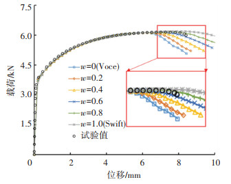 图 5 不同权重系数下硬化模型预测曲线 Fig. 5 Hardening model prediction curves with different weighting coefficients
 2.3 本构模型的准确性验证为了验证非相关流动准则的Drucker屈服函数与Swift-Voce硬化模型对TRIP780的描述精度,将上述模型编译为VUMAT子程序嵌入ABAQUS/Explicit中进行有限元验证,对除狗骨试样外其他试样均进行了数值模拟。
在试样的有限元建模中,为提高计算效率,剪切试样采用厚度方向的对称约束建立了1/2模型,其余试样均施加3个方向的对称约束建立了1/8模型。为保证有限元模拟的可靠性,主要变形区网格尺寸设置为0.1 mm的六面体,网格类型设置为C3D8R,所有模型均在ABAQUS 6.14-4中进行显式求解。
将试样模拟得到的载荷-位移曲线与试验值对比,均取得了较高的预测精度。图 6对比了圆孔与剪切试样3个取向的试验与模拟载荷-位移曲线。可以看出,采用非相关流动准则的Drucker屈服函数与Swift-Voce硬化模型可以很好地描述TRIP780不同取向和应力状态下的塑性力学行为,为韧性断裂的研究提供了可靠基础。
Fig. 6
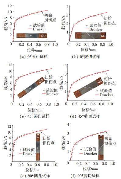 图 6 不同轧制方向试样的试验与模拟载荷-位移曲线比较 Fig. 6 Comparison between test and simulated load-displacement curves of specimens with different rolling directions
 3 半耦合韧性断裂准则 3.1 半耦合韧性断裂准则的构建材料宏观力学性能受到其微观组织变化的影响,当材料出现内部损伤时,其硬化能力亦会下降。由于内部损伤的积累,材料的承载能力不断下降并最终破裂,文献[32]针对DP590提出了一种描述内部损伤的思路,见图 7。此方法将破裂与初始损伤明确区分开,这里的初始损伤(即裂纹萌生)描述的是微观组织在一定长度范围内发生不可逆退化时的微观行为,它对应于由所有微观不连续点引起的材料退化的一个临界阶段[23]。初始损伤发生后,材料的力学性能发生退化,承载能力下降,损伤累积至临界点后,承载能力达到极限,宏观表现为材料断裂。与耦合型韧性断裂不同的是,该模型在初始损伤点之前的力学行为完全由本构模型确定,初始损伤点之后材料的承载能力才开始下降,进入损伤软化阶段,更能够描述材料内部的损伤演化机制。
Fig. 7
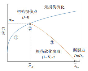 图 7 半耦合韧性断裂模型原理 Fig. 7 Evolution of semi-coupled ductile fracture model
 3.1.1 初始损伤判定模型半耦合断裂模型可以分为初始损伤的出现和损伤后软化两部分,初始损伤点前阶段由2节标定的本构模型确定,初始损伤的判定则需要借助合适的模型。损伤出现前,材料的力学性能不受影响,在变形到达一定程度时开始出现损伤,损伤点同时与所处应力状态有关,因此,非耦合断裂模型可以作为初始损伤判定模型。为准确描述材料在不同应力状态下的初始损伤时刻,将Lou等[21]提出的DF2012模型修改为初始损伤判定模型,将原始模型中的断裂应变修正为初始损伤应变,其形式为
$\begin{gathered}\int_0^{\bar{\varepsilon}_{, \mathrm{p}}}\left(\frac{2}{\sqrt{L^2+3}}\right)^{c_1}\left(\frac{\langle 1+3 \eta\rangle}{2}\right)^{c_2} \mathrm{~d} \bar{\varepsilon}_{\mathrm{p}}=c_3 \\\langle x\rangle=\left\{\begin{array}{l}x, x \geqslant 0 \\0, x <0\end{array}\right.\end{gathered}$ (6)
式中:
3.1.2 损伤演化模型为描述材料变形过程中内部损伤对硬化行为的影响,需要构建损伤演化模型。基于损伤累积表现为材料的刚度退化和应力软化的事实,此处引入表征损伤累积的损伤变量D并耦合到塑性模型中,构建的损伤演化模型形式如下:
$\mathit{\Phi}=\bar{\sigma}_{\text {eq }}-\bar{\sigma}(\bar{\varepsilon})(1-D) \leqslant 0$ (7)
式中:
Hillerborg等[36]基于耗散能提出了一种脆性断裂的断裂能量模型,Lian等[29]将其用于断裂模型损伤变量的定义,其形式如下:
$\dot{D}=\frac{\sigma_{\mathrm{y} 0} L_{\mathrm{e}}}{2 G_{\mathrm{f}}} \dot{\varepsilon}_{\mathrm{p}}$ (8)
式中:Gf是打开一个单位面积裂缝所需的能量,Le为有限元中与积分点相关的特征长度,σy0为损伤起始时的屈服应力值,
式(8)将损伤变量表示为应变的线性函数,但忽视了应力状态的影响。事实上,金属的损伤过程是内部微观孔洞的生长过程,主要表现为高应力三轴度下的长大机制与低应力三轴度下的拉长扭转机制。对正向应力而言,低应力三轴度对孔洞生长的抑制作用会导致断裂延后,因此考虑将表征不同应力状态对损伤影响的应力三轴度参数η引入损伤变量模型中。将应力三轴度以-1/3截止值的形式引入式(8),以乘积形式表示其对损伤累积的作用,同时增加指数项调整系数m,修正后的损伤变量D如下:
$\dot{D}=\frac{\sigma_{\mathrm{y} 0} L_{\mathrm{e}}}{2 G_{\mathrm{f}}}\left\langle\frac{1+3 \eta}{2}\right\rangle^m \dot{\varepsilon}_{\mathrm{p}}$ (9)
式中:
值得注意的是,该损伤演化模型假定应力三轴度小于0时材料不积累损伤。根据以上定义,构建的半耦合韧性断裂模型表述为:材料进入塑性变形阶段后继续变形至初始损伤时刻,而后内部损伤开始累积并表现为力学性能下降,当损伤变量D累积至截止值Dcr时判定断裂发生。以上3个阶段的表达式如下:
$D=\left\{\begin{array}{l}0, \bar{\varepsilon}_{\mathrm{p}}<\bar{\varepsilon}_{\mathrm{i}, \mathrm{p}} \\\int_{\bar{\varepsilon}_{\mathrm{i}, \mathrm{p}}}^{\bar{\varepsilon}_{\mathrm{f}, \mathrm{p}}} \frac{\sigma_{\mathrm{y} 0} L_{\mathrm{e}}}{2 G_{\mathrm{f}}}\left\langle\frac{1+3 \eta}{2}\right\rangle^m \mathrm{~d} \bar{\varepsilon}_{\mathrm{p}}, \bar{\varepsilon}_{\mathrm{i}, \mathrm{p}} \leqslant \bar{\varepsilon}_{\mathrm{p}}<\bar{\varepsilon}_{\mathrm{f}, \mathrm{p}} \\D_{\mathrm{cr}}, \bar{\varepsilon}_{\mathrm{p}}=\bar{\varepsilon}_{\mathrm{f}, \mathrm{p}}\end{array}\right.$ (10)
3.2 半耦合韧性断裂准则在TRIP780高强钢中的应用 3.2.1 参数标定构建的半耦合断裂模型有两部分需要标定,分别是初始损伤判定模型和损伤演化模型。DF2012初始损伤判定模型共有3个材料参数(c1, c2, c3)需要标定,选用涉及宽应力状态范围的圆孔试样、带R5缺口试样和剪切试样进行标定。模型准确标定的前提是获取等效塑性应变、应力三轴度和罗德参数等数据,本研究采用试验-模拟混合法获取上述参数。图 8~10为圆孔、带R5缺口与剪切试样对比单元的应变与应力状态参数演化,由于试样变形过程中往往先产生内部损伤继而扩展,因此选取应变集中内层单元捕捉应力三轴度与罗德参数。可以看出,圆孔试样与带R5缺口试样的应力三轴度与罗德参数变化不明显,剪切试样的应力三轴度趋于平稳,罗德参数逐渐降低。因此,借助试验-模拟混合法获取的相关参数可以用于标定初始损伤模型。
Fig. 8
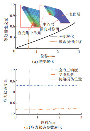 图 8 圆孔试样的应变和应力状态参数演化 Fig. 8 Evolution of strain and stress state parameters of round-hole specimen
 Fig. 9
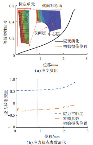 图 9 带R5缺口试样的应变和应力状态参数演化 Fig. 9 Evolution of strain and stress state parameters of specimen with R5 notch
 Fig. 10
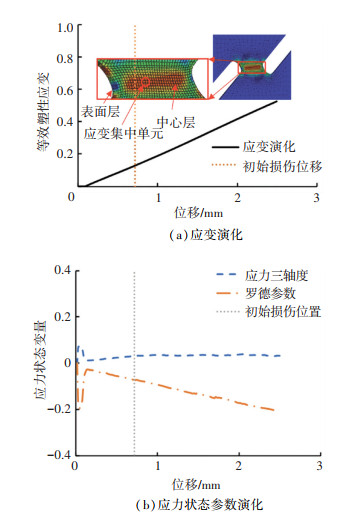 图 10 剪切试样的应变和应力状态参数演化 Fig. 10 Evolution of strain and stress state parameters of shear specimen
 将试验测得初始损伤位移与选取单元的等效塑性应变、应力三轴度和罗德参数等应力状态变量汇总于表 2,标定得到DF2012参数值为c1=2.062,c2=0.122 4,c3=0.161。
表 2
圆孔 0.687 0.150 0.329 -0.925
R5缺口 0.990 0.098 0.537 -0.264
剪切 0.711 0.130 0.028 -0.072
表 2 3种试样的初始损伤位移和应力状态参数 Tab. 2 Initial damage displacement and stress state parameters of three specimens
材料发生初始损伤后即进入损伤演化阶段。式(9)中,σy0为初始损伤时的屈服应力,可以通过有限元模拟获取,Le为有限元模型单元大小参数,本研究中根据最小网格尺寸取0.1。因此损伤演化模型需要标定的参数有Gf、m、Dcr,其中Dcr定义为损伤截止值,在标定时可以设置一个较大值(本研究中设为1),即假定材料不发生断裂,确定其他参数后再对其进行标定。本研究中采用逆向工程法对参数Gf和m进行标定,选用圆孔试样与剪切试样的载荷位移数据,目标函数如下:
$\min E_{\mathrm{rr}}=\sum\limits_{i=1}^n\left(\frac{F_{i, \mathrm{pred}}}{F_{i, \exp }}-1\right)^2$ (11)
式中:Fi, pred与Fi, exp分别为试样载荷的模拟值与试验值,i与n为试样的分析步与分析步总数,Err为误差平方和。
为便于优化,基于Isight平台,联合MATLAB与ABAQUS进行参数优化,选择Downhill-Simplex算法,求解得到Gf=147,m=0.108。将标定参数代入圆孔试样的有限元模拟中,输出危险单元点的损伤变量值,当Dcr取0.165时,断裂位移预测值与试验值几乎一致。
3.2.2 有限元验证为验证构建的半耦合韧性断裂模型的准确性,将其编写为VUMAT断裂子程序并嵌入ABAQUS/Explicit中,用于预测TRIP780高强钢的损伤断裂行为。不同试样的模拟结果见图 11,同时对比了未耦合损伤的载荷-位移曲线。
Fig. 11
 图 11 试验和模拟载荷-位移曲线对比 Fig. 11 Comparison of test and simulated load-displacement curves
 试验-模拟对比结果显示,5种试样在初始损伤时刻前的模拟载荷-位移曲线与试验值基本一致,此部分由所选用的本构模型控制,初始损伤判定模型同样表现出较高的模拟精度。耦合损伤的半耦合模型在变形后期可以准确描述材料损伤软化引起的载荷下降效应,对5种试样均表现出较高的描述精度,未耦合损伤的载荷模拟值在变形后期依旧保持上升趋势,逐渐偏离试验值。另外,预测的断裂位移与试验值具有很高的一致性,为了直观反映预测精度,将断裂位移的试验与预测值汇总于图 12,同时汇总所有试样的极限断裂应变见表 3。
表 3
0.612 0.544 0.562 0.594 0.430
表 3 断裂应变模拟值 Tab. 3 Simulated values of fracture strain
Fig. 12
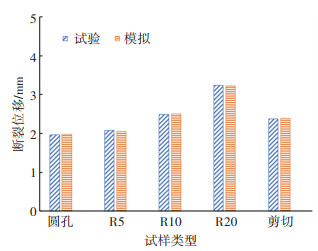 图 12 试验和模拟断裂位移对比 Fig. 12 Comparison of test and simulated fracture displacement
 由图 12可知,构建的半耦合韧性断裂准则准确预测了不同试样的断裂,最大相对误差出现在R5试样,为1.31%。同时,模型的优越性更在于描述高强钢变形后期的损伤诱导软化效应,并验证了从纯剪切至平面应变的宽应力状态范围的准确性。此外,参数标定的工作量远小于耦合型断裂模型,便于应用。
值得注意的是,受限于相机的采集频率等试验因素,未能捕捉到试样的断裂起始点。以剪切试样为例,有限元模拟中断裂点从试样中心区萌生,这与模型中的内部损伤演化(裂纹扩展)假设契合。事实上,试样的裂纹往往从中心区扩展,但由于缺乏试验验证仍待后续研究中讨论。
4 结论针对高强钢变形后期损伤诱导软化的断裂行为,构建了一种半耦合韧性断裂准则。引入损伤变量的定义描述材料内部损伤并耦合到塑性模型中,修改DF2012模型为初始损伤判定模型,将构建的模型应用于TRIP780高强钢板材从纯剪切至平面应变宽应力状态范围的断裂预测,主要结论如下:
1) 由非相关流动准则的Drucker各向异性屈服函数的屈服应力模拟值可知,Drucker各向异性屈服函数适于描述TRIP780钢板的各向异性屈服。其联合Swift-Voce硬化模型组成的本构模型可以准确表征TRIP780的塑性力学行为。
2) 构建了一种半耦合韧性断裂准则以描述材料的损伤诱导软化行为。模型分为三部分:变形初期的塑性阶段、初始损伤出现点和损伤演化阶段。塑性阶段完全由本构模型确定,初始损伤点由修正的DF2012初始损伤判定模型确定,损伤演化阶段定义了损伤变量D以描述损伤累积,同时引入应力三轴度表征不同应力状态对损伤积累程度的影响。
3) 修正的DF2012初始损伤判定模型很好地预测了材料的初始损伤点,而后利用逆向工程法标定了损伤演化模型。试验和有限元模拟的载荷-位移曲线对比显示构建的半耦合韧性断裂准则准确描述了TRIP780高强钢板的损伤诱导软化现象,且预测的断裂位移最大相对误差仅为1.31%,适用于描述具有损伤诱导软化现象高强钢的断裂行为。
参考文献
[1] 李扬, 刘汉武, 杜云慧, 等. 汽车用先进高强钢的应用现状和发展方向[J]. 材料导报, 2011, 25(13): 101.
LI Yang, LIU Hanwu, DU Yunhui, et al. Applications and developments of AHSS in automobile industry[J]. Materials Reports, 2011, 25(13): 101.
[2] 李光霁, 刘新玲. 汽车轻量化技术的研究现状综述[J]. 材料科学与工艺, 2020, 28(5): 47.
LI Guangji, LIU Xinling. Literature review on research and development of automotive lightweight technology[J]. Materials Science and Technology, 2020, 28(5): 47. DOI:10.11951/j.issn.1005-0299.20190232
[3] ZACKAY V F, PARKER E R, FAHR D, et al. The enhancement of ductility in high-strength steels[J]. ASM Transactions Quarterly, 1967, 60(2): 252.
[4] 王亚东, 刘红祎, 王亚芬, 等. 汽车用先进高强钢成形性能研究[J]. 中国金属通报, 2016(7): 82.
WANG Yadong, LIU Hongyi, WANG Yafen, et al. Study on formability of advanced high strength steel for automobile[J]. China Metal Bulletin, 2016(7): 82.
[5] 于建民, 张治民, 赵龙. 高强度钢发动机壳体温挤压成形工艺优化设计[J]. 锻压技术, 2009, 34(1): 80.
YU Jianmin, ZHANG Zhimin, ZHAO Long. Design optimization for warm forming process of engine shell of high strength steel[J]. Forging & Stamping Technology, 2009, 34(1): 80. DOI:10.3969/j.issn.1000-3940.2009.01.022
[6] KACHANOV L M. Rupture time under creep conditions[J]. International Journal of Fracture, 1999, 97: 11. DOI:10.1023/A:1018671022008
[7] LEMAITRE J. A continuous damage mechanics model for ductile fracture[J]. Journal of Engineering Materials and Technology, 1985, 107(1): 83. DOI:10.1115/1.3225775
[8] LEMAITRE J. A course on damage mechanics[M]. Heidelberg: Springer Berlin, 1996: 39.
[9] CHABOCHE J L. Continuous damage mechanics—a tool to describe phenomena before crack initiation[J]. Nuclear Engineering and Design, 1981, 64(2): 233. DOI:10.1016/0029-5493(81)90007-8
[10] CHABOCHE J L. Continuum damage mechanics: part I—general concepts[J]. Journal of Applied Mechanics, 1988, 55(1): 59. DOI:10.1115/1.3173661
[11] CHABOCHE J L. Continuum damage mechanics: part Ⅱ—damage growth, crack initiation, and crack growth[J]. Journal of Applied Mechanics, 1998, 55(1): 65. DOI:10.1115/1.3173662
[12] GURSON A L. Continuum theory of ductile rupture by void nucleation and growth: part I—yield criteria and flow rules for porous ductile media[J]. Journal of Engineering Materials and Technology, 1977, 99(1): 2. DOI:10.1115/1.3443401
[13] TVERGAARD V. On localization in ductile materials containing spherical voids[J]. International Journal of Fracture, 1982, 18(4): 237. DOI:10.1007/BF00015686
[14] TVERGAARD V, NEEDLEMAN A. Analysis of the cup-cone fracture in a round tensile bar[J]. Acta Metallurgica, 1984, 32(1): 157. DOI:10.1016/0001-6160(84)90213-X
[15] NEEDLEMAN A, TVERGAARD V. An analysis of ductile rupture modes at a crack tip[J]. Journal of the Mechanics and Physics of Solids, 1987, 35(2): 151. DOI:10.1016/0022-5096(87)90034-2
[16] COCKCROFT M G, LATHAM D J. Ductility and the workability of metals[J]. Journal of the Institute of Metals, 1968, 96: 33.
[17] OH S I, CHEN C C, KOBAYASHI S, et al. Ductile fracture in axisymmetric extrusion and drawing—part 2: workability in extrusion and drawing[J]. Journal of Manufacturing Science and Engineering, 1979, 101(1): 36. DOI:10.1115/1.3439471
[18] MCCLINTOCK F A. A criterion for ductile fracture by the growth of holes[J]. Journal of Applied Mechanics, 1968, 35(2): 363. DOI:10.1115/1.3601204
[19] RICE J R, TRACEY D M. On the ductile enlargement of voids in triaxial stress fields[J]. Journal of the Mechanics and Physics of Solids, 1969, 17(3): 201. DOI:10.1016/0022-5096(69)90033-7
[20] BAI Yuanli, WIERZBICKI T. Application of extended Mohr-Coulomb criterion to ductile fracture[J]. International Journal of Fracture, 2010, 161: 1. DOI:10.1007/s10704-009-9422-8
[21] LOU Yanshan, HUH H, LIM S, et al. New ductile fracture criterion for prediction of fracture forming limit diagrams of sheet metals[J]. International Journal of Solids and Structures, 2012, 49(25): 3605. DOI:10.1016/j.ijsolstr.2012.02.016
[22] LOU Yanshan, YOON J W, HUH H. Modeling of shear ductile fracture considering a changeable cut-off value for stress triaxiality[J]. International Journal of Plasticity, 2014, 54: 56. DOI:10.1016/j.ijplas.2013.08.006
[23] LOU Yanshan, CHEN Lin, CLAUSMEYER T, et al. Modeling of ductile fracture from shear to balanced biaxial tension for sheet metals[J]. International Journal of Solids and Structures, 2017, 112: 169. DOI:10.1016/j.ijsolstr.2016.11.034
[24] 张赛军, 李康镇, 张昆, 等. 韧性断裂准则参数标定及其在DP590中的应用[J]. 哈尔滨工业大学学报, 2021, 53(1): 63.
ZHANG Saijun, LI Kangzhen, ZHANG Kun, et al. Parameter calibration of ductile fracture criterion and its application on DP590[J]. Journal of Harbin Institute of Technology, 2021, 53(1): 63. DOI:10.11918/201912028
[25] 陈志伟, 赵长财, 董国疆, 等. 高强铝板韧性断裂准则参数求解及其成形极限[J]. 中国有色金属学报, 2020, 30(4): 763.
CHEN Zhiwei, ZHAO Changcai, DONG Guojiang, et al. Calculation of ductile fracture parameters and forming limit of high-strength aluminum sheet[J]. The Chinese Journal of Nonferrous Metals, 2020, 30(4): 763. DOI:10.11817/j.ysxb.1004.0609.2020-35777
[26] HU Qi, LI Xifeng, HAN Xianhong, et al. A new shear and tension based ductile fracture criterion: modeling and validation[J]. European Journal of Mechanics - A/Solids, 2017, 66: 370. DOI:10.1016/j.euromechsol.2017.08.005
[27] YAMANE K, SHIMODA K, KURODA K, et al. A new ductile fracture criterion for skew rolling and its application to evaluate the effect of number of rolls[J]. Journal of Materials Processing Technology, 2021, 291: 116989. DOI:10.1016/j.jmatprotec.2020.116989
[28] LI Yaning, WIERZBICKI T. Prediction of plane strain fracture of AHSS sheets with post-initiation softening[J]. International Journal of Solids and Structures, 2010, 47(17): 2316. DOI:10.1016/j.ijsolstr.2010.04.028
[29] LIAN Junhe, SHARAF M, ARCHIE F, et al. A hybrid approach for modelling of plasticity and failure behaviour of advanced high-strength steel sheets[J]. International Journal of Damage Mechanics, 2013, 22(2): 188. DOI:10.1177/1056789512439319
[30] MVNSTERMANN S, LIAN J, PVTZ F, et al. Comparative study on damage evolution during sheet metal forming of steels DP600 and DP1000[J]. Journal of Physics: Conference Series, 2017, 896: 012074. DOI:10.1088/1742-6596/896/1/012074
[31] LIU Wenqi, LIAN Junhe, MVNSTERMANN S, et al. Prediction of crack formation in the progressive folding of square tubes during dynamic axial crushing[J]. International Journal of Mechanical Sciences, 2020, 176: 105534. DOI:10.1016/j.ijmecsci.2020.105534
[32] ZHANG Saijun, DING Weiyang, LI Kanzhen, et al. Prediction of ductile fracture for DP590 high-strength steel with a new semi-coupled ductile fracture criterion[J]. Journal of the Brazilian Society of Mechanical Sciences and Engineering, 2022, 44: 17. DOI:10.1007/s40430-021-03275-z
[33] MVNSTERMANN S, UTHAISANGSUK V, PRAHL U, et al. Experimental and numerical failure criteria for sheet metal forming[J]. Steel Research International, 2007, 78(10/11): 762. DOI:10.1002/srin.200706283
[34] DRUCKER C D. Relation of experiments to mathematical theories of plasticity[J]. Journal of Applied Mechanics, 1949, 16(4): 349. DOI:10.1115/1.4010009
[35] LOU Yanshan, YOON J W. Anisotropic yield function based on stress invariants for BCC and FCC metals and its extension to ductile fracture criterion[J]. International Journal of Plasticity, 2018, 101: 125. DOI:10.1016/j.ijplas.2017.10.012
[36] HILLERBORG A, MODéER M, PETERSSON P, et al. Analysis of crack formation and crack growth in concrete by means of fracture mechanics and finite elements[J]. Cement and Concrete Research, 1976, 6(6): 773. DOI:10.1016/0008-8846(76)90007-7
