李雅楠,付永庆
(哈尔滨工程大学 信息与通信工程学院,哈尔滨 150001)
摘要:
为提高多进制混沌通信系统的性能,解决Duffing混沌系统受混沌同步技术限制的问题,本文设计了基于Duffing振子的四进制混沌数字通信系统.利用二进制Duffing混沌调制方法与正交幅度调制技术(Quadrature Amplitude Modulation, QAM)结合的思想,实现了基于Duffing振子的四进制混沌调制.同时,根据Duffing振子解调信号的原理,文中简化了域分割检测器的结构,并构建了基于同频Duffing振子阵列的混沌信号解调器和基于Duffing振子的四进制混沌数字接收机,完成了基于Duffing振子的四进制混沌数字通信系统的设计.仿真结果表明:基于Duffing振子的四进制混沌信号发射机完成了对基带信号的四进制混沌调制;简化的域分割检测器可自动识别Duffing振子相轨迹,且其结构和算法更易实现;基于Duffing振子的四进制混沌数字接收机完成了四进制Duffing混沌信号的非相干解调,该混沌数字通信系统的误码率等性能优于经典的四进制混沌数字通信系统.本文针对Duffing振子混沌通信技术,改善了基于Duffing振子的四进制混沌数字通信系统的设计方法,为多进制混沌通信系统的构建提供了参考.
关键词: 混沌通信 Duffing振子 QAM 非相干解调 域分割检测器
DOI:10.11918/201906031
分类号:TN918
文献标识码:A
基金项目:国家自然科学基金(61172038)
A quaternary chaotic digital communication system based on Duffing oscillator
LI Yanan,FU Yongqing
(College of Information and Communication Engineering, Harbin Engineering University, Harbin 150001, China)
Abstract:
To improve the property of M-ary chaotic communication system and develop the chaotic synchronization technique of Duffing chaotic system, a quaternary chaotic digital communication system using Duffing oscillator is presented in this paper. The binary chaotic modulation method with Duffing oscillator was combined with Quadrature Amplitude Modulation (QAM) to realize quaternary chaotic modulation with Duffing oscillator. Meanwhile, according to the demodulation theory of Duffing oscillator, the zone partition was simplified, and the chaotic signal demodulator based on Duffing oscillators array as well as the quaternary chaotic digital receiver based on Duffing oscillator was constructed, which realized the quaternary chaotic digital communication system design based on Duffing oscillator. Simulation results show that the quaternary chaotic modulation could be achieved by the quaternary chaotic signal transmitter. The simplified zone partition could recognize the phase trajectory of the Duffing oscillator with easier realization of structure and algorithm. The quaternary chaotic digital receiver based on Duffing oscillator could realize noncoherent demodulation of the quaternary Duffing chaotic signal, and results show that the BER property of the chaotic system was better than that of the classical quaternary chaotic systems. Therefore, the quaternary chaotic digital communication system based on Duffing oscillator introduced in this paper simplifies the chaotic modulation method and noncoherent demodulation with Duffing oscillator, which provides reference for the construction of M-ary chaotic communication system.
Key words: chaotic communication Duffing oscillator QAM noncoherent demodulation zone partition
李雅楠, 付永庆. 一种四进制Duffing混沌数字通信系统[J]. 哈尔滨工业大学学报, 2020, 52(5): 157-164. DOI: 10.11918/201906031.

LI Yanan, FU Yongqing. A quaternary chaotic digital communication system based on Duffing oscillator[J]. Journal of Harbin Institute of Technology, 2020, 52(5): 157-164. DOI: 10.11918/201906031.

基金项目 国家自然科学基金(61172038) 作者简介 李雅楠(1988-), 女, 博士研究生; 付永庆(1956-), 男, 教授, 博士生导师 通信作者 付永庆, fuyongqing@hrbeu.edu.cn 文章历史 收稿日期: 2019-06-04
Abstract Full text Figures/Tables PDF
一种四进制Duffing混沌数字通信系统
李雅楠, 付永庆


哈尔滨工程大学 信息与通信工程学院, 哈尔滨 150001
收稿日期: 2019-06-04
基金项目: 国家自然科学基金(61172038)
作者简介: 李雅楠(1988-), 女, 博士研究生; 付永庆(1956-), 男, 教授, 博士生导师
通信作者: 付永庆, fuyongqing@hrbeu.edu.cn
摘要: 为提高多进制混沌通信系统的性能,解决Duffing混沌系统受混沌同步技术限制的问题,本文设计了基于Duffing振子的四进制混沌数字通信系统.利用二进制Duffing混沌调制方法与正交幅度调制技术(Quadrature Amplitude Modulation,QAM)结合的思想,实现了基于Duffing振子的四进制混沌调制.同时,根据Duffing振子解调信号的原理,文中简化了域分割检测器的结构,并构建了基于同频Duffing振子阵列的混沌信号解调器和基于Duffing振子的四进制混沌数字接收机,完成了基于Duffing振子的四进制混沌数字通信系统的设计.仿真结果表明:基于Duffing振子的四进制混沌信号发射机完成了对基带信号的四进制混沌调制;简化的域分割检测器可自动识别Duffing振子相轨迹,且其结构和算法更易实现;基于Duffing振子的四进制混沌数字接收机完成了四进制Duffing混沌信号的非相干解调,该混沌数字通信系统的误码率等性能优于经典的四进制混沌数字通信系统.本文针对Duffing振子混沌通信技术,改善了基于Duffing振子的四进制混沌数字通信系统的设计方法,为多进制混沌通信系统的构建提供了参考.
关键词: 混沌通信 Duffing振子 QAM 非相干解调 域分割检测器
A quaternary chaotic digital communication system based on Duffing oscillator
LI Yanan, FU Yongqing


College of Information and Communication Engineering, Harbin Engineering University, Harbin 150001, China
Abstract: To improve the property of M-ary chaotic communication system and develop the chaotic synchronization technique of Duffing chaotic system, a quaternary chaotic digital communication system using Duffing oscillator is presented in this paper. The binary chaotic modulation method with Duffing oscillator was combined with Quadrature Amplitude Modulation (QAM) to realize quaternary chaotic modulation with Duffing oscillator. Meanwhile, according to the demodulation theory of Duffing oscillator, the zone partition was simplified, and the chaotic signal demodulator based on Duffing oscillators array as well as the quaternary chaotic digital receiver based on Duffing oscillator was constructed, which realized the quaternary chaotic digital communication system design based on Duffing oscillator. Simulation results show that the quaternary chaotic modulation could be achieved by the quaternary chaotic signal transmitter. The simplified zone partition could recognize the phase trajectory of the Duffing oscillator with easier realization of structure and algorithm. The quaternary chaotic digital receiver based on Duffing oscillator could realize noncoherent demodulation of the quaternary Duffing chaotic signal, and results show that the BER property of the chaotic system was better than that of the classical quaternary chaotic systems. Therefore, the quaternary chaotic digital communication system based on Duffing oscillator introduced in this paper simplifies the chaotic modulation method and noncoherent demodulation with Duffing oscillator, which provides reference for the construction of M-ary chaotic communication system.
Keywords: chaotic communication Duffing oscillator QAM noncoherent demodulation zone partition
混沌通信是通信领域中的一个重要研究方向,其非线性特性使混沌通信技术在常规通信和保密通信应用中都有着巨大潜力.其中,混沌信号因其非周期特性和分形特性而不易被干扰和预测,在安全性、大容量等方面具有优势,所以在保密通信领域得到了快速发展.
在混沌通信技术中,接收端的解调方式分为相干解调和非相干解调[1].由于混沌同步问题尚未得到有效解决,非相干解调方式的应用更普遍,是现代混沌通信系统的重要解调方式[2].其中,CSK、DCSK等混沌数字调制技术的研究较为深入,但此类通信系统存在传输速率较低、误码率性能差强人意等劣势[1].虽然QCSK系统提高了传输速率,但其设计成本较高且系统BER性能几乎并未得到改善;MC-DCSK系统提高了传输速率并改善了BER性能,但其增加了系统复杂性并降低了数据安全性[3-4];其他相关的通信系统也有传输速率或安全性低等缺点[5-9].近些年来,使用Duffing振子的混沌通信技术逐渐发展起来.其中,Zapateiro等[10]提出使用Duffing混沌序列进行混沌通信,但其并未研究多进制调制方式;Zaher[11]利用参数控制实现使用Duffing振子进行多进制调制的目的,但同步技术仍是难点;王有维等[12]通过Duffing振子频率参数控制方法完成保密通信; Liao等[13]对Duffing振子信号的幅度进行调制用于混沌通信,但其解调和同步算法较复杂;Rigatos[14]使用Duffing振子产生载波信号和位同步信号,系统消耗和复杂度较高.这些研究[10-16]说明了Duffing振子在混沌通信领域的应用潜力.目前,基于Duffing振子的混沌调制技术多集中于参数调制方式和相图控制方法,多进制调制方法较少.同时,现有技术说明了基于Duffing振子的混沌通信技术引起了学者们的关注,且其调制方式、同步技术是该混沌通信的重点、难点.本文旨在提出一种基于Duffing振子的混沌通信系统,其调制方式易于实现,利用非相干解调方法来解调该混沌信号,不受混沌同步技术的限制,为其工程应用提供新思路.
1 基于Duffing振子的混沌信号调制方法 1.1 二进制Duffing混沌信号调制方法利用Duffing振子进行混沌调制是基于映射的思想,使用其时域信号的周期性来完成二进制信号的调制.Duffing振子的参数敏感性使其时域周期信号的初相位具有任意性,非周期信号的波形具有不可预测性,这一特点保障了该混沌信号的保密性.下面,将介绍二进制Duffing混沌信号的调制方法.
不失一般性,Duffing振子的数学表达式为
$\left\{ \begin{array}{l}{{\dot y}_1}\left( t \right) = \omega {y_2}\left( t \right),\\{\rm{ }}{{\dot y}_2}\left( t \right) = \omega [ - k{y_2}\left( t \right) + {y_1}\left( t \right) - y_1^3\left( t \right) + \\{\rm{ }}{\kern 1pt} {\kern 1pt} {\kern 1pt} {\kern 1pt} {\kern 1pt} {\kern 1pt} {\kern 1pt} {\kern 1pt} {\kern 1pt} {\kern 1pt} {\kern 1pt} {\kern 1pt} {\kern 1pt} {\kern 1pt} {\kern 1pt} {\kern 1pt} {\kern 1pt} {\kern 1pt} {\kern 1pt} {\kern 1pt} {\kern 1pt} {\kern 1pt} {\kern 1pt} {\kern 1pt} {\kern 1pt} {\kern 1pt} {\kern 1pt} {\kern 1pt} {\kern 1pt} {\kern 1pt} {\kern 1pt} {\kern 1pt} {\kern 1pt} {\kern 1pt} {\kern 1pt} {\kern 1pt} {\kern 1pt} {\gamma _{\rm{c}}}{\rm{cos}}\left( {\omega t + {\varphi _0}} \right) + ax\left( t \right)].\end{array} \right.$ (1)
式中:y1(t)和y2(t)为方程状态变量;γccos(ωt+φ0)为振子的内部驱动力,其角频率为ω=2πf0,频率为f0,初相位为φ0,幅度γc使Duffing振子相轨迹处于临界混沌态;k为阻尼系数;a为外部信号注入强度因子;x(t)=d(t)cos(ωt+φ1)是初相位为φ1的外部输入信号;d(t)为基带信号,d(t)经BPSK调制后得到x(t).整理γccos(ωt+φ0)和ax(t),这两项的和为Duffing振子的内部总驱动力A(t),即
$\begin{array}{l}A\left( t \right) = {\gamma _{\rm{c}}}{\rm{cos}}\left( {\omega t + {\varphi _0}} \right) + ax\left( t \right) = \\\;\;\;\;\;\;\;\;\;\;\;\bar \gamma (t){\rm{cos}}[\omega t + {\varphi _0} + \theta (t)].\end{array}$ (2)
式中
Fig. 1
 图 1 Duffing振子输出信号y1(t)时域波形 Fig. 1 Waveform of time domain signal y1(t) by Duffing oscillator
 1.2 四进制Duffing混沌信号调制方法由二进制Duffing混沌信号的调制原理可知,该信号的传输速率较低,且带宽利用率较差.为了避免这一缺点,本文提出了基于Duffing振子的四进制混沌信号调制方法,目的在于增强系统的保密性,增加传输速率和带宽利用率,其具体调制方法如下.
使用混沌振子产生多进制信号需要振子具有多吸引子,虽然Duffing振子不具备这一特点,但可以将二进制Duffing混沌信号调制方法与QAM技术结合,对两路混沌信号进行QAM调制,再从单一信道中发送出去,即可完成调制.基于该思想,四进制Duffing混沌信号的调制步骤为
1) 使用串并转换器把基带数据序列分成I、Q两路子数据序列,记为bit0和bit1;
2) 按照二进制Duffing混沌信号调制方法,分别对bit0和bit1序列进行调制,生成两路二进制Duffing混沌信号i(t)和q(t);
3) 对两路二进制Duffing混沌信号进行QAM调制,产生四进制Duffing混沌信号xt(t).
按照上述方法得到了四进制Duffing混沌信号的调制方案,见图 2.同时,根据该调制原理搭建了基于Duffing振子的四进制混沌信号发射机,其结构见图 3.
Fig. 2
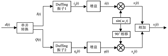 图 2 四进制Duffing混沌信号调制方法 Fig. 2 Quaternary chaotic modulation method based on Duffing oscillator
 由图 3可知,该发射机是将基带信号d(t)进行串并转换后分为I、Q两路信号,对两路信号分别进行BPSK调制,各自控制一个工作在临界态的Duffing振子,分别产生二进制Duffing混沌信号,两路信号经QAM调制后发送.图 4给出了基于Duffing振子的四进制混沌信号发射机的主要信号仿真波形.
Fig. 3
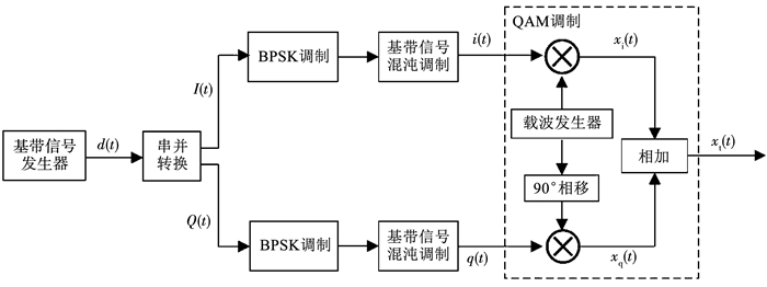 图 3 基于Duffing振子的四进制混沌信号发射机 Fig. 3 Quaternary chaotic signal transmitter based on Duffing oscillator
 Fig. 4
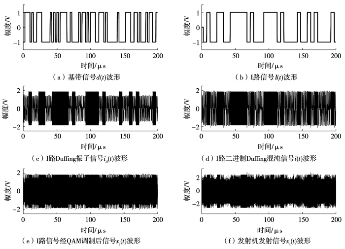 图 4 基于Duffing振子的四进制混沌信号发射机仿真波形 Fig. 4 Simulation waveforms of the quaternary chaotic signal transmitter based on Duffing oscillator
 图 4中,(b)为发射机中I路信号,(d)为其二进制Duffing混沌信号,Duffing混沌信号中的周期态和混沌态时域波形分别对应I路高、低电平信号.此外,图 4(a)为基带信号,(f)为发射机发送信号,对比二者可发现,该发射机实现了混沌调制.由发射机结构可知,I、Q两路信号经QAM调制后发射,设两路混沌调制信号分别为xi(t)和xq(t),发送信号xt(t)可表示为
$\begin{array}{l}{x_{\rm{t}}}\left( t \right) = {x_{\rm{i}}}\left( t \right) + {x_{\rm{q}}}\left( t \right) = i(t){\rm{sin}}({\omega _{\rm{c}}}t) + \\\;\;\;\;\;\;\;\;\;\;\;q(t){\rm{cos}}({\omega _{\rm{c}}}t).\end{array}$ (3)
式中i(t)和q(t)分别为图 3中I、Q两路中的二进制Duffing混沌信号.该方法在没有增加无线传输系统带宽的情况下提高了系统传输速率,达到了预期目的.
2 一种简化的域分割检测器目前,对Duffing振子相轨迹的判断方法已经由最初的人眼判断发展为自动识别技术.其中,域分割检测器[20]因其简单的结构和算法得到了重视,它将Duffing振子二维相轨迹信息转化为一维时域信号,可高效、自动的识别Duffing振子相轨迹,本文对其结构进行了简化.
当Duffing振子相轨迹为混沌态时,相轨迹的纵坐标,即式(1)中y2(t)的值在固定范围内;当相轨迹为大尺度周期态时,y2(t)的值不断穿越这一固定范围,见图 5.
Fig. 5
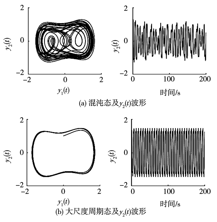 图 5 Duffing振子相轨迹及y2(t)波形 Fig. 5 Waveform of signal y2(t) and the phase trajectories of Duffing oscillator
 根据信号y2(t)的这一特点,得到简化的域分割检测器的数学表达式为
${{\bar y}_2}\left( t \right) = \left\{ \begin{array}{l} + 1,\left| {{y_2}\left( t \right)} \right| < R;\\ - 2,\left| {{y_2}\left( t \right)} \right| \ge R.\end{array} \right.$ (4)
式中R为检测阈值,该阈值由γc和a的取值决定,通过多次实验可确定R的取值.且式中“+1”和“-2”的取值可根据系统参数改变,使检测器的输出经低通滤波器后约为“+1”和“-1”的电平即可.简化的域分割检测器结构见图 6.
Fig. 6
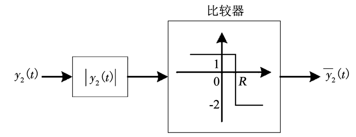 图 6 简化的域分割检测器结构 Fig. 6 Structure of the simplified zone partition
 该简化的域分割检测器的仿真结果见图 7.仿真系统是使用Duffing振子检测BPSK信号,仿真波形是在基带信号速率为1 MHz,BPSK信号和Duffing振子频率为36.05 MHz,系统采样频率为360.5 MHz,信噪比为9 dB条件下获得的.图 7(a)为基带信号波形,经BPSK调制后输入Duffing振子,(d)为简化的域分割检测器输出波形.对比二者可发现,域分割检测器输出的高电平与基带信号的高电平对应,快速变化的高低电平与基带信号的低电平对应,说明该简化的域分割检测器同样实现了相轨迹识别的功能.
Fig. 7
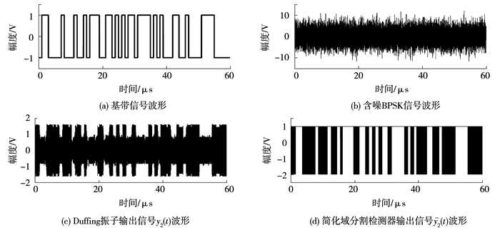 图 7 简化的域分割检测器仿真结果 Fig. 7 Simulation results of the simplified zone partition
 3 二进制Duffing混沌信号的解调原理Duffing振子检测信号的原理是利用其参数敏感性,通过相轨迹状态(大尺度周期态和混沌态)指示基带信号电平.二进制Duffing混沌信号为周期或非周期信号,当信号为周期信号时,其频率与Duffing振子内部驱动力相同;当信号为非周期信号时,其频率较分散,周期和非周期信号的幅度不同,使用这一特点解调该混沌信号.
令式(1)中Duffing振子内部驱动力γccos(ωt+φ0)的幅度为γ0,使相轨迹为混沌态.外部输入信号x(t)=s(t)+n(t)中s(t)=a1cos(ωt+φ1)是初相位为φ1的待检信号,n(t)是加性高斯白噪声.不考虑n(t)时,Duffing振子内部总驱动力A(t)为
$\begin{array}{l}A\left( t \right) = {\gamma _0}{\rm{cos}}\left( {\omega t + {\varphi _0}} \right) + as\left( t \right) = \\\;\;\;\;\;\;\;\;\;\;\;\bar \gamma (t){\rm{cos}}[\omega t + {\varphi _0} + \varphi (t)].\end{array}$ (5)
式中:
Fig. 8
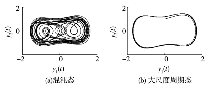 图 8 Duffing振子的相轨迹 Fig. 8 Phase trajectories of Duffing oscillator
 然而,A(t)的幅度γ(t)除了与γ0、a和a1相关外,还受φ1和φ0的限制.若要求Duffing振子能正确解调出待检信号,其内部驱动力初相位与待检信号初相位需要满足一定条件,这种相位关联条件被称为Duffing振子的信号接收窗[17].此外,由于二进制Duffing混沌信号的初相位具有任意性,这就需要接收端对待检信号初相位具有免疫性.基于这些要求,本文使用同频Duffing振子阵列、域分割检测器、加法器和积分清洗滤波器构建了基于同频Duffing振子阵列的混沌信号解调器[17],见图 9.
Fig. 9
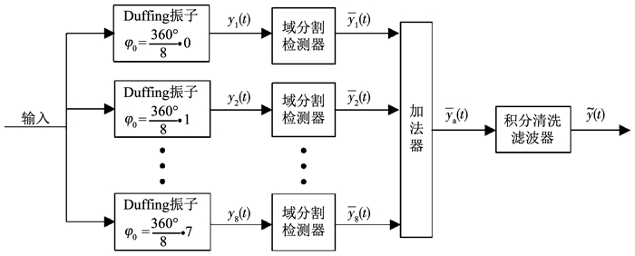 图 9 基于同频Duffing振子阵列的混沌信号解调器 Fig. 9 Chaotic signal demodulator based on Duffing oscillators array
 图 9中,同频Duffing振子阵列由内部驱动力初相位依次相差360°/8、其它参数相同的8个Duffing振子构成.当具有任意初相位的待检信号出现时,阵列中有多个振子可检测出待检信号,再经域分割检测器、加法器等结构的处理后即可完成待检信号的非相干解调.各Duffing振子的检测结果yi(t)(i=1, 2, …, 8)由域分割检测器转化为一维时域信号yi(t)(i=1, 2, …, 8),使用加法器处理yi(t)为
${{\bar y}_{\rm{a}}}\left( t \right) = \sum\limits_{i = 1}^8 {{{\bar y}_i}\left( t \right)} \left( {i = 1,2, \cdots ,8.} \right).$ (6)
最后,将ya(t)送入积分清洗滤波器为
$\tilde y\left( t \right) = \int_{\left( {k - 1} \right)T}^{kT} {{{\bar y}_{\rm{a}}}} \left( t \right){\rm{d}}t.$ (7)
使用积分清洗滤波器滤除加权信号ya(t)中的高次谐波,从而恢复出基带信号波形.图 11(b)、(e)分别为通信系统中I路信号和混沌信号解调器解调出的信号.对比二者可发现,混沌信号解调器实现了二进制Duffing混沌信号的非相干解调.该解调器的优点在于结构简单,更易工程实现.
Fig. 10
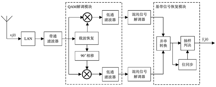 图 10 基于Duffing振子的四进制混沌数字接收机 Fig. 10 Quaternary chaotic digital receiver based on Duffing oscillator
 Fig. 11
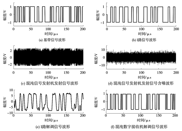 图 11 基于Duffing振子的四进制混沌数字通信系统仿真波形 Fig. 11 Simulation results of the quaternary chaotic digital communication system based on Duffing oscillator
 4 基于Duffing振子的四进制混沌数字接收机 4.1 基于Duffing振子的四进制混沌数字接收机使用Duffing振子进行混沌信号调制和解调的方法已经介绍完毕,接下来,根据四进制Duffing混沌信号的调制原理,本文搭建了基于Duffing振子的四进制混沌数字接收机,其结构见图 10.该接收机由接收机前端、QAM解调模块、混沌信号解调器、基带信号恢复模块四部分构成.各模块的主要功能如下:
1) 接收机前端.该结构为低噪声放大器(LNA)和带通滤波器,分别起到接收信号并放大、滤除带外噪声的作用.
2) QAM解调模块.该模块的作用是对接收信号进行QAM解调,获得两路并行的二进制Duffing混沌信号.
3) 混沌信号解调器.在并行的两路中分别设置基于同频Duffing振子阵列的混沌信号解调器,该解调器结构见图 9,用于解调二进制Duffing混沌信号.
4) 基带信号恢复模块.该模块由并串转换、位同步等结构组成,用于恢复基带信号.
综上,接收端将接收到的四进制Duffing混沌信号进行QAM解调,然后对获得的两路二进制Duffing混沌信号进行解调,最终通过并串转换、抽样判决等结构恢复出基带码元yo(t),从而完成对四进制Duffing混沌信号的解调.
4.2 仿真结果根据搭建的四进制混沌数字发射机和接收机,最终完成了基于Duffing振子的四进制混沌数字通信系统设计,并对该通信系统进行了仿真和分析讨论.该通信系统的主要参数设计如下:基带信号d(t)的码元速率为f1=400 KHz,发射机和接收机中Duffing振子的频率为f0=4 MHz,发射端QAM调制载波的频率为fc=50 MHz,系统采样频率为250 MHz.此外,发射端信号xt(t)的符号平均功率为
${P_{{\rm{sav}}}} = \frac{1}{T}\int_0^{\rm{T}} {x_{\rm{t}}^2} \left( t \right){\rm{d}}t = \frac{1}{T}\int_0^{\rm{T}} {[x_{\rm{i}}^2\left( t \right) + x_{\rm{q}}^2\left( t \right)]} {\rm{d}}t.$ (8)
式中T=1/f0=0.25 μs.该发射机的符号平均能量与噪声功率谱密度之比为
$\frac{{{E_{{\rm{sav}}}}}}{{{N_0}}} = \frac{{{P_{{\rm{sav}}}}\cdot T}}{{{N_0}}} = \frac{{{P_{{\rm{sav}}}}}}{{{N_0}\cdot B}}.$ (9)
式中B=4 MHz,N0为噪声功率谱密度.利用式(9)可计算出在不同Esav/N0条件下的N0值,仿真得到该系统的误码率曲线.
首先,图 11给出了基于Duffing振子的四进制混沌数字通信系统中主要信号的仿真波形.该仿真波形是在Esav/N0=10 dB条件下获得的.对比图 11(a)和(f),虽然有延时,但二者码元波形相同,说明该接收机完成了四进制Duffing混沌信号的非相干解调.为了更好的评价这一通信系统的误码率性能,测得了该混沌数字通信系统的误码率曲线,见图 12.
Fig. 12
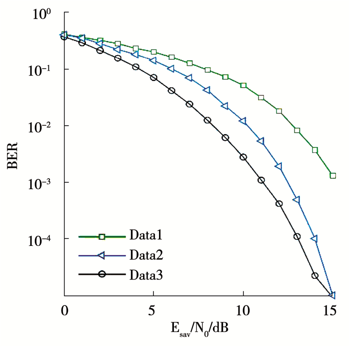 图 12 基于Duffing振子的四进制混沌数字通信系统的误码率曲线 Fig. 12 BER curves of the quaternary chaotic digital communication system based on Duffing oscillator
 图 12中,Data3为基于Duffing振子的四进制混沌数字通信系统的误码率曲线,Data1为QCSK通信系统[21]的误码率曲线,对比Data1和Data3可见,该系统误码率性能优于QCSK系统.此外,Data2为基于Hamilton振子的混沌QAM四进制通信系统[22]的误码率曲线,在低信噪比情况下,该通信系统误码率优于Hamilton通信系统,当Esav/N0=15 dB时,二者性能接近.特殊的,当Esav/N0=13 dB时,误码率约为10-4,适用实际工程环境.此外,从系统复杂度来看,该结合二进制调制方法和QAM技术的系统,较其它使用参数调制技术的系统[11],结构更简单;在发射端,由于不需要相图传递信息,所以降低了系统功耗[12];在接收端,该系统使用混沌信号解调器完成信号的非相干解调,避免了混沌同步技术的限制,算法较其它Duffing多进制通信系统更易实现[11, 16].同时,该四进制混沌数字通信系统的调制方法可用于多进制通信系统的搭建,以满足工程需求.然而,该系统的保密性有待提高,以增强系统的安全性.
5 结论本文通过阐述二进制Duffing混沌信号的调制原理,提出了基于Duffing振子的四进制混沌信号调制方法,并构建了基于Duffing振子的四进制混沌信号发射机.同时,介绍了简化的域分割检测器的结构和实现方法,仿真结果验证了该结构的可行性.根据Duffing振子解调二进制Duffing混沌信号的原理,使用同频Duffing振子阵列和域分割检测器等结构搭建了基于同频Duffing振子阵列的混沌信号解调器,以实现二进制Duffing混沌信号的非相干解调,进而构建了基于Duffing振子的四进制混沌数字接收机,完成了基于Duffing振子的四进制混沌数字通信系统的设计,并对该四进制混沌数字通信系统进行了仿真验证,仿真结果说明了该系统的通信性能较好.接下来将研究如何提高该系统的解调性能和完成其硬件实现,包括参数优化、系统的FPGA设计等工作.
参考文献
[1] 杨华.基于DCSK的混沌数字调制研究[D].南京: 南京邮电大学, 2014
YANG Hua. Research on chaotic digital modulations based on DCSK[D]. Nanjing: Nanjing University of Posts and Telecommunications, 2014
[2] 时颖.非相干DCSK系统性能分析[D].哈尔滨: 哈尔滨工业大学, 2006
SHI Ying. The performance analysis of non-coherent DCSK system[D]. Harbin: Harbin Institute of Technology, 2006
[3] KADDOUM G, SHOKRANEH F. Analog network coding for multi-user multi-carrier differential chaos shift keying communication system[J]. IEEE Transactions on Wireless Communications, 2015, 14(3): 1492. DOI:10.1109/TWC.2014.2367508
[4] KADDOUM G, RICHARDSON F D, GAGNON F. Design and analysis of a multi-carrier differential chaos shift keying communication system[J]. IEEE Transactions on Communications, 2013, 61(8): 3281. DOI:10.1109/TCOMM.2013.071013.130225
[5] XU Weikai, WANG Lin, CHEN Guanrong. Performance analysis of the CS-DCSK/BPSK communication system[J]. IEEE Transactions on Circuits and Systems I:Regular Papers, 2014, 61(9): 2624. DOI:10.1109/TCSI.2014.2312477
[6] KADDOUM G, SOUJERI E, ARCILA C, et al. I-DCSK:An improved noncoherent communication system architecture[J]. IEEE Transactions on Circuits and Systems II:Express Briefs, 2015, 62(9): 901. DOI:10.1109/tcsii.2015.2435831
[7] YANG Hua, JIANG Guoping. Reference-modulated DCSK:A novel chaotic communication scheme[J]. IEEE Transactions on Circuits and Systems II:Express Briefs, 2013, 60(4): 232. DOI:10.1109/tcsii.2013.2251949
[8] KOLUMBAN G. Theoretical noise performance of correlator-based chaotic communications schemes[J]. IEEE Transactions on Circuits and Systems I:Fundamental Theory and Applications, 2000, 47(12): 1692. DOI:10.1109/81.899921
[9] YANG Hua, TANG W K S, CHEN Guanrong, et al. System design and performance analysis of orthogonal multi-level differential chaos shift keying modulation scheme[J]. IEEE Transactions on Circuits and Systems I:Regular Papers, 2016, 63(1): 146. DOI:10.1109/TCSI.2015.2510622
[10] ZAPATEIRO M, VIDAL Y, ACHO L. A secure communication scheme based on chaotic Duffing oscillators and frequency estimation for the transmission of binary-coded messages[J]. Communications in Nonlinear Science and Numerical Simulation, 2014, 19(4): 991. DOI:10.1016/j.cnsns.2013.07.029
[11] ZAHER A A. Duffing oscillators for secure communication[J]. Computers and Electrical Engineering, 2018, 71: 77. DOI:10.1016/j.compeleceng.2018.07.005
[12] 王有维, 石要武, 王丽萍, 等. 利用相空间轨迹产生混沌脉冲序列的方法研究[J]. 信息与控制, 2008, 37(6): 686.
WANG Youwei, SHI Yaowu, WANG Liping, et al. A chaotic pulse sequence generating method based on phase space trajectory[J]. Information and Control, 2008, 37(6): 686. DOI:10.3969/j.issn.1002-0411.2008.06.009
[13] LIAO Tehlu L, WAN Peiyen, YAN Junjuh. Design of synchronized large-scale chaos random number generators and its application to secure communication[J]. Applied Science-Basel, 2019, 9(1): 185. DOI:10.3390/app9010185
[14] RIGATOS G. A chaotic communication system of improved performance based on the derivative-free nonlinear Kalman filter[J]. International Journal of Systems Science, 2016, 47(9): 2152. DOI:10.1080/00207721.2014.978412
[15] ZAHER A A. Secure communication using Duffing oscillators[C]//Proceedings of the 2011 IEEE International Conference on Signal and Image Processing Applications. Kuala Lumpur, Malaysia: IEEE, 2011: 563. DOI: 10.1109/ICSIPA.2011.6144150
[16] CHERNEVA G, DIMKINA E. Chaotic masking approach based on the Duffing oscillator[C]//Proceedings of the 9th International Conference on ELEKTRO 2012. Rajeck Teplice, Slovakia: IEEE, 2012: 42. DOI: 10.1109/ELEKTRO.2012.6225605
[17] FU Yongqing, LI Yanan, ZHANG Lin, et al. The DPSK signal noncoherent demodulation receiver based on the Duffing oscillators array[J]. International Journal of Bifurcation and Chaos, 2016, 26(13): 1650216. DOI:10.1142/S0218127416502163
[18] FU Yongqing, LI Xingyuan, LI Yanan, et al. Chaos M-ary modulation and demodulation method based on Hamilton oscillator and its application in communication[J]. Chaos, 2013, 23(1): 821. DOI:10.1063/1.4790831
[19] YANG Chaosan, ZHANG Tianqi, PAN Yi, et al. Demodulation of QAM signals based on chaotic oscillators[C]//Proceedings of the 20136th International Congress on Image and Signal Processing. Hangzhou, China: IEEE, 2013: 1504. DOI: 10.1109/CISP.2013.6743913
[20] FU Yongqing, WU Dongmei, ZHANG Lin, et al. A circular zone partition method for identifying Duffing oscillator state transition and its application to BPSK signal demodulation[J]. Science China-Information Sciences, 2011, 54(6): 1274. DOI:10.1007/s11432-011-4199-6
[21] GALIAS Z, MAGGIO G M. Quadrature chaos-shift keying:Theory and performance analysis[J]. IEEE Transactions on Circuits and Systems I:Fundamental Theory and Applications, 2001, 48(12): 1510. DOI:10.1109/TCSI.2001.972858
[22] 李星渊.基于Hamilton振子的混沌四进制数字通信系统设计及其仿真研究[D].哈尔滨: 哈尔滨工程大学, 2016
LI Xingyuan. The design and simulation research of chaotic 4-ary digital communication system based on Hamilton oscillator[D]. Harbin: Harbin Engineering University, 2016
