Huimin Han1,2, Dong-Jin Yoo1,2,Yan Liang1,2
(1. Department of Computer Aided Mechanical Design Engineering, Daejin University, Pocheon-si 487-711, South Korea;2.Department of Mechanical and Electrical Engineering, Hainan Institute of Science and Technology,Haikou 571126, China)
Abstract:
An effective and simple design method for co-continuous composite material construction is proposed by using a hybrid methodology with triply periodic minimal surface (TPMS) cellular topology and the volumetric distance field (VDF). After generating a set of VDF-based features for the given exterior shape and desired internal core structure, a series of simple modifications in distance fields enabled us to obtain an arbitrarily-shaped complex co-continuous composite material computational model. Design results and manufactured prototypes through 3D printing technology show that the proposed methodology has the potential to open a new paradigm for producing multifunctional next generation co-continuous composite materials which are impossible to design and manufacture using traditional CAD and CAM.
Key words: triply periodic minimal surface (TPMS) cellular topology volumetric distance field (VDF) co-continuous composite material model basic feature 3D printing technology
DOI:10.11916/j.issn.1005-9113.18074
Clc Number:TH122
Fund:
Huimin Han, Dong-Jin Yoo, Yan Liang. Co-continuous Composite Material Design Using the Volumetric Distance Field Based on Analytic Shape Functions[J]. Journal of Harbin Institute of Technology (New Series), 2019, 26(1): 88-96. DOI: 10.11916/j.issn.1005-9113.18074.

Fund Sponsored by the Scientific Research Foundation of the Higher Education Institutions of Hainan Province of China (Grant No. Hnky2018-101) Corresponding author Dong-Jin Yoo, E-mail: michelle531@sina.com Article history Received: 2018-06-25
Contents Abstract Full text Figures/Tables PDF
Co-continuous Composite Material Design Using the Volumetric Distance Field Based on Analytic Shape Functions
Huimin Han1,2, Dong-Jin Yoo1

 , Yan Liang1,2
 1. Department of Computer Aided Mechanical Design Engineering, Daejin University, Pocheon-si 487-711, South Korea;
2. Department of Mechanical and Electrical Engineering, Hainan Institute of Science and Technology, Haikou 571126, China
Received: 2018-06-25
Fund: Sponsored by the Scientific Research Foundation of the Higher Education Institutions of Hainan Province of China (Grant No. Hnky2018-101)
Corresponding author: Dong-Jin Yoo, E-mail: michelle531@sina.com
Abstract: An effective and simple design method for co-continuous composite material construction is proposed by using a hybrid methodology with triply periodic minimal surface (TPMS) cellular topology and the volumetric distance field (VDF). After generating a set of VDF-based features for the given exterior shape and desired internal core structure, a series of simple modifications in distance fields enabled us to obtain an arbitrarily-shaped complex co-continuous composite material computational model. Design results and manufactured prototypes through 3D printing technology show that the proposed methodology has the potential to open a new paradigm for producing multifunctional next generation co-continuous composite materials which are impossible to design and manufacture using traditional CAD and CAM.
Keywords: triply periodic minimal surface (TPMS) cellular topology volumetric distance field (VDF) co-continuous composite material model basic feature 3D printing technology
1 Introduction At present, fiber reinforced and particle composites are widely used in most engineering areas[1-3]. These materials have excellent wear resistance, stiffness, and relatively low density compressive strength, but they are limited in terms of volume fraction enhancement in matrices. Moreover, the components in fiber reinforced and particle composites are not sufficiently interconnected and have no continuous phases. Therefore, this makes the interconnectivity of each phase worse[4]. Based on this background, we designed and manufactured a new composite material, namely co-continuous composite material (CCM). Its morphologies are interpenetrating topologies of two or more phases, with all phases continuous in all three-dimensional (3D) spaces[5]. CCMs are widespread both in natural and synthetic materials, such as human bones, block copolymers, etc. In combination with the advantages of two or more phases, CCMs can optimize the properties of all phases together, including energy dissipation, toughness, stiffness, impact resistance, strength, etc[6].
Recent theoretical studies have shown that the interface structures between the liquid and the glass polymer are similar to triply periodic minimal surface (TPMS)[6]. These co-continuous two-phase interface structures have optimal simultaneous high-performance and multi-function such as a combination of high electrical (or thermal) conductivity together with high bulk modulus[7]. It has been concluded that these optimal physical and mechanical properties are obtained by adjusting topological and geometrical arrangements of the constituents[6].
Through other recent studies, the structural adhesives formed by epoxy polymer are widely used in engineering structure. Due to their brittleness, the fracture toughness of epoxy polymer can be enhanced by inserting second phases in nanometer scale. Kinloch et al.[8] and Brooker et al.[9] noticed that the proportion of thermoplastic toughener for the hybrid material increases as a result of morphological variation to co-continuous structure. Therefore, this kind of co-continuous structure with two or more free-standing and interpenetrating phases has been noticed for thermoplastic modified epoxy. In order to understand physical phase separation and mechanical properties after morphologic variation, Carolan et al.[10] reported the numerical studies of co-continuous polymer. The experimental results show that compared with the traditional structure, the mechanical properties of the co-continuous structure are significantly different. It is obvious that this structure can be used to create a co-continuous polymer with adjustable energy absorption and mechanical properties.
Man-made or natural CCMs consist of two or more different materials with different properties. They can overcome the defects of a single material and combine the advantages of various materials. For instance, by mixing soft and hard materials, we can obtain a new composite material with better mechanical properties including toughness, strength and stiffness, and energy dissipation.
A cutting-edge type of micro-structure was used to construct CCMs in this paper, which is known as triply periodic minimal surface (TPMS). TPMSs are the repetitive micro-structures in 3D space with infinitely continuous smooth surfaces. Because TPMSs can divide the geometric space into two or more complex intertwined sub-spaces[11], they have been applied to design and develop interpenetrating phase composites in many research areas[11-13].
Different from other methods, the main innovation of the proposed method is to develop a new design algorithm. In order to eliminate the time-consuming manual operation in the modeling process and to build an automatic design framework, we propose a completely different design method. Unlike the traditional design method based on the explicit geometric transformation for the basic geometry needed, we developed a new implicit design method based on the field function level set calculation. All geometric solids used in 3D modeling process were described by using the volumetric distance field (VDF) based on analytic shape functions, and the core internal structures of all geometric solids were constructed with TPMS-based cellular topologies. By combining the TPMS-based cellular topologies and the VDF, we can generate a CCM computational model with arbitrary external shape and controllable core internal structure.
The paper is organized as follows. In Section 2, we introduce core structure construction algorithm by using TPMS-based topologies and VDF. Section 3 is focused on proving that the proposed design method can construct arbitrary shape CCM models effectively and simply in a consistent design framework. Several prototypes were manufactured by using the 3D AM technology. Finally, concluding remarks and ideas for future research are given in Section 4.
2 Methods 2.1 TPMS-based Topologies Although many types of TPMSs have been introduced in the previous works, only four surfaces including P surface, G surface, D surface, and IWP surface were used to describe the algorithms related to the CCM model design method proposed in this paper, as shown in Fig. 1. The readers can consult previous works for more detailed contents regarding on the TPMS-based topology generation[11, 14-20].
Fig.1
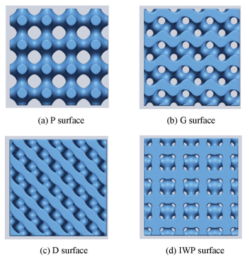 Fig.1 TPMS-based topologies
 2.2 Volumetric Distance Field The volumetric distance field (VDF) can express a shape efficiently and easily. Generally, the VDF is described as a rectangular scalar field of the distances to the shape in rectangular volumetric region. By using negative and positive values to distinguish the outside and inside of a solid shape, the inside of a solid shape was identified by positive value, and the outside of a solid shape was identified by negative value in this paper. The readers can consult previous works for more detailed contents regarding the VDF calculation[17-18].
2.3 TPMS-Based Core Structure Construction Algorithm Let us consider a simple example using a T-shaped CCM solid model design. First, the VDF for the upper boundary triangulation of a cube were calculated, which corresponds to the upper part shape of a T-shaped solid model to be created(i.e. ?upper_cube). Second, we calculated the VDF for the lower boundary triangulation of a cube, which corresponds to the lower part shape of a T-shaped solid model to be created (i.e. ?lower_cube). Finally, the VDF for a T-shaped solid model was created by using union Boolean operation.
$\begin{array}{*{20}{c}}{{\phi _{{\rm{T - shaped\_solid}}}} = {\phi _{{\rm{upper\_cube}}}} \cup {\phi _{{\rm{lower\_cube}}}} = }\\{\max \left( {{\phi _{{\rm{upper\_cube}}}},{\phi _{{\rm{lower\_cube}}}}} \right)}\end{array}$ (1a)
$\begin{array}{*{20}{c}}{{\phi _{{\rm{upper\_cube}}}} = {\phi _{{\rm{upper\_cube\_}}x}} \cap {\phi _{{\rm{upper\_cube\_}}y}} \cap {\phi _{{\rm{upper\_cube\_}}z}} = }\\{\min \left( {\min \left( {{\phi _{{\rm{upper\_cube\_}}x}},{\phi _{{\rm{upper\_cube\_}}y}}} \right),{\phi _{{\rm{upper\_cube\_}}z}}} \right)}\end{array}$ (1b)
${\phi _{{\rm{lower\_cube}}}} = {\phi _{{\rm{lower\_cube\_}}x}} \cap {\phi _{{\rm{lower\_cube\_}}y}} \cap {\phi _{{\rm{lower\_cube\_}}z}}$ (1c)
${\phi _{{\rm{upper\_cube\_}}x}} = \left\{ {\begin{array}{*{20}{c}}\begin{array}{l}x - {x_{{\rm{cu}}}} - 0.5{U_X},\\ - 0.5{U_X} - \left( {x - {x_{{\rm{cu}}}}} \right),\end{array}&\begin{array}{l}x \ge {x_{{\rm{cu}}}}\\x < {x_{{\rm{cu}}}}\end{array}\end{array}} \right.$ (1d.1)
${\phi _{{\rm{upper\_cube\_}}y}} = \left\{ {\begin{array}{*{20}{c}}\begin{array}{l}y - {y_{{\rm{cu}}}} - 0.5{U_Y},\\ - 0.5{U_Y} - \left( {y - {y_{{\rm{cu}}}}} \right),\end{array}&\begin{array}{l}y \ge {y_{{\rm{cu}}}}\\y < {y_{{\rm{cu}}}}\end{array}\end{array}} \right.$ (1d.2)
${\phi _{{\rm{upper\_cube\_}}z}} = \left\{ {\begin{array}{*{20}{c}}\begin{array}{l}z - {z_{{\rm{cu}}}} - 0.5{U_Z},\\ - 0.5{U_Z} - \left( {z - {z_{{\rm{cu}}}}} \right),\end{array}&\begin{array}{l}z \ge {z_{{\rm{cu}}}}\\z < {z_{{\rm{cu}}}}\end{array}\end{array}} \right.$ (1d.3)
${\phi _{{\rm{lower\_cube\_}}x}} = \left\{ {\begin{array}{*{20}{c}}\begin{array}{l}x - {x_{{\rm{cl}}}} - 0.5{L_X},\\ - 0.5{L_X} - \left( {x - {x_{{\rm{cl}}}}} \right),\end{array}&\begin{array}{l}x \ge {x_{{\rm{cl}}}}\\x < {x_{{\rm{cl}}}}\end{array}\end{array}} \right.$ (1e.1)
${\phi _{{\rm{lower\_cube\_}}y}} = \left\{ {\begin{array}{*{20}{c}}\begin{array}{l}y - {y_{{\rm{cl}}}} - 0.5{L_Y},\\ - 0.5{L_Y} - \left( {y - {y_{{\rm{cl}}}}} \right),\end{array}&\begin{array}{l}y \ge {y_{{\rm{cl}}}}\\y < {y_{{\rm{cl}}}}\end{array}\end{array}} \right.$ (1e.2)
${\phi _{{\rm{lower\_cube\_}}z}} = \left\{ {\begin{array}{*{20}{c}}\begin{array}{l}z - {z_{{\rm{cl}}}} - 0.5{L_Z},\\ - 0.5{L_Z} - \left( {z - {z_{{\rm{cl}}}}} \right),\end{array}&\begin{array}{l}z \ge {z_{{\rm{cl}}}}\\z < {z_{{\rm{cl}}}}\end{array}\end{array}} \right.$ (1e.3)
where UX, UY, UZ represent the upper cube sizes, and LX, LY, LZ represent the lower cube sizes in the x, y, and z directions, respectively. xcu, ycu, and zcu represent the center coordinates of the upper cube, and xcl, ycl, and zcl represent the center coordinates of the lower cube in the x, y, and z directions, respectively. In this case, we gave the parameters UX=10.0 mm, UY=30.0 mm, UZ=10.0 mm, and LX=20.0 mm, LY=10.0 mm, LZ=10.0 mm, and xcu=-5.0 mm, ycu=0 mm, zcu=0 mm, and xcl=10.0 mm, ycl=0 mm, zcl=0 mm.
Fig. 2 shows the VDF computing process for a T-shaped solid model based on a basic feature. A 2D schematic diagram for the computing process is shown in Fig. 2(a). A 3D solid model was generated as shown in Fig. 2 (b).
Fig.2
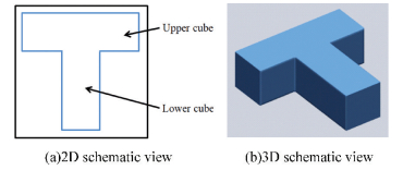 Fig.2 VDF computing process for a T-shaped solid model based on a basic feature
 After building the VDF for an external shape solid model based on a given basic feature, we can calculate the VDFs for the needed core structure by using TPMS-based internal cellular topologies and VDF-based Boolean operations.
To do this, we first described the TPMS-based internal cellular topologies of the phase A and the phase B by ?TPMS_A and ?TPMS_B. Second, the intersection Boolean operation was performed between the upper cube and the TPMS internal cellular topology of the phase A. We created the upper core element of the phase A as follows:
$\begin{array}{*{20}{c}}{{\phi _{{\rm{upper\_TPMS\_A}}}} = {\phi _{{\rm{upper\_cube}}}} \cap {\phi _{{\rm{TPMS\_A}}}} = }\\{\min \left( {{\phi _{{\rm{upper\_cube}}}},{\phi _{{\rm{TPMS\_A}}}}} \right)}\end{array}$ (2)
Third, we also created the upper core element of the phase B by implementing the intersection Boolean operation between the upper cube and the TPMS internal cellular topology of the phase B. The upper core element of the phase B is defined by:
$\begin{array}{*{20}{c}}{{\phi _{{\rm{upper\_TPMS\_B}}}} = {\phi _{{\rm{upper\_cube}}}} \cap {\phi _{{\rm{TPMS\_B}}}} = }\\{\min \left( {{\phi _{{\rm{upper\_cube}}}},{\phi _{{\rm{TPMS\_B}}}}} \right)}\end{array}$ (3)
In the same way, starting from the intersection Boolean operation between the lower cube and the TPMS internal cellular topology of the phase A, we can create the lower core element of the phase A defined by:
$\begin{array}{*{20}{c}}{{\phi _{{\rm{lower\_TPMS\_A}}}} = {\phi _{{\rm{lower\_cube}}}} \cap {\phi _{{\rm{TPMS\_A}}}} = }\\{\min \left( {{\phi _{{\rm{lower\_cube}}}},{\phi _{{\rm{TPMS\_A}}}}} \right)}\end{array}$ (4)
Then, we can also create the lower core element of the phase B by the intersection Boolean operation between the lower cube and the TPMS internal cellular topology of the phase B defined by:
$\begin{array}{*{20}{c}}{{\phi _{{\rm{lower\_TPMS\_B}}}} = {\phi _{{\rm{lower\_cube}}}} \cap {\phi _{{\rm{TPMS\_B}}}} = }\\{\min \left( {{\phi _{{\rm{lower\_cube}}}},{\phi _{{\rm{TPMS\_B}}}}} \right)}\end{array}$ (5)
In this case, ?TPMS_A and ?TPMS_B represent the TPMS internal cellular topologies of the phase A and the phase B, respectively. We used the P surface nodal equation to define the two internal cellular topologies as follows:
${\phi _{{\rm{TPMS\_A}}}} = \cos \left( X \right) + \cos \left( Y \right) + \cos \left( Z \right) + {C_1}$ (6)
${\phi _{{\rm{TPMS\_B}}}} = - \left[ {\cos \left( X \right) + \cos \left( Y \right) + \cos \left( Z \right) + {C_2}} \right]$ (7)
where C1 and C2 indicate two offset values in two normal directions. In this case, we gave the parameters C1=0 and C2=0.
Once VDFs for the upper core elements of the phase A and the phase B, and the lower core elements of the phase A and the phase B have been calculated, the final core structure elements can be generated which are applied in constructing T-shaped CCM computational model with two continuous phases, namely the phase A and the phase B. The final core structure element of the phase A was created through implementing the union Boolean operation between the upper and lower core elements of the phase A as follows:
$\begin{array}{*{20}{c}}{{\phi _{{\rm{T - shaped\_core\_A}}}} = {\phi _{{\rm{upper\_TPMS\_A}}}} \cup {\phi _{{\rm{lower\_TPMS\_A}}}} = }\\{\max \left( {{\phi _{{\rm{upper\_TPMS\_A}}}},{\phi _{{\rm{lower\_TPMS\_A}}}}} \right)}\end{array}$ (8)
Similarly, the final core structure element of the phase B was created by performing the union Boolean operation between the upper and lower core elements of the phase B as follows:
$\begin{array}{*{20}{c}}{{\phi _{{\rm{T - shaped\_core\_B}}}} = {\phi _{{\rm{upper\_TPMS\_B}}}} \cup {\phi _{{\rm{lower\_TPMS\_B}}}} = }\\{\max \left( {{\phi _{{\rm{upper\_TPMS\_B}}}},{\phi _{{\rm{lower\_TPMS\_B}}}}} \right)}\end{array}$ (9)
A flow diagram of TPMS-based CCM design algorithm is shown in Fig. 3. The CCM computational model can be composed of two core structure elements of the phase A and the phase B by using Eqs. (8) and (9). Fig. 4 shows the more detailed construction process of T-shaped CCM model.
Fig.3
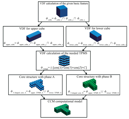 Fig.3 Flow diagram of TPMS-based CCM design algorithm
 Fig.4
 Fig.4 Construction process of T-shaped CCM model
 Various T-shaped CCM models with different types of TPMS cellular topology are shown in Fig. 5. As shown in Fig. 5(a), we can accurately control the volume fraction of each phase within the upper and lower parts of the T-shaped CCM model by adjusting C1 and C2. We can vary the number of cells within a core structure, as shown in Fig. 5(e) and (f).
Fig.5
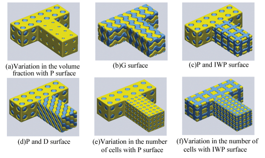 Fig.5 Various T-shaped CCM models with different types of TPMS-based cellular topology
 Although a relatively simple example has been handled, all design algorithms for the construction of TPMS-based CCM can be robustly and easily used in more highly complex basic features without losing its generality, as shown in Figs. 6 and 7.
Fig.6
 Fig.6 Various ring-shaped CCMs designed by using ring-shaped basic feature
 Fig.7
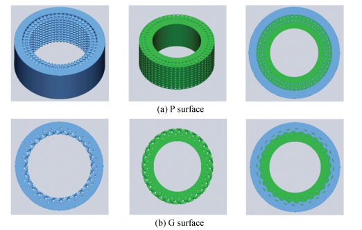 Fig.7 A variety of hybrid ring-shaped CCMs constructed by using hybrid ring-shaped basic feature
 Various ring-shaped CCMs can be designed by using ring-shaped basic feature as follows:
${\phi _{{\rm{solid\_ring}}}} = {\phi _{{\rm{solid\_cylinder\_outer}}}} - {\phi _{{\rm{solid\_cylinder\_inner}}}}$ (10a)
${\phi _{{\rm{solid\_cylinder\_outer}}}} = {\phi _{{\rm{solid\_circle\_outer}}}} \cap {\phi _{{\rm{solid\_plane\_}}x}}$ (10b)
${\phi _{{\rm{solid\_cylinder\_outer}}}} = {\phi _{{\rm{solid\_circle\_inner}}}} \cap {\phi _{{\rm{solid\_plane\_}}x}}$ (10c)
${\phi _{{\rm{solid\_circle\_outer}}}} = \sqrt {{{\left( {y - {y_{\rm{c}}}} \right)}^2} + {{\left( {z - {z_{\rm{c}}}} \right)}^2}} - {r_{\rm{o}}}$ (10d)
${\phi _{{\rm{solid\_circle\_inner}}}} = \sqrt {{{\left( {y - {y_{\rm{c}}}} \right)}^2} + {{\left( {z - {z_{\rm{c}}}} \right)}^2}} - {r_{\rm{i}}}$ (10e)
${\phi _{{\rm{solid\_plane\_}}x}} = \left\{ {\begin{array}{*{20}{c}}\begin{array}{l}x - {x_{\rm{c}}} - 0.5H,\\ - 0.5H - \left( {x - {x_{\rm{c}}}} \right),\end{array}&\begin{array}{l}x \ge {x_{\rm{c}}}\\x < {x_{\rm{c}}}\end{array}\end{array}} \right.$ (10f)
where xc represents the center coordinate of the plane in the x directions, and H represents the height of the plane. yc and zc represent the center coordinates of the circle in the y and z directions, respectively. ro represents the radius of the outer circle, and ri represents the radius of the inner circle. Eq. (10) can be simply modified when creating the rings in the y and z directions, respectively. In this case, we gave the parameters xc=yc=zc=0 mm, H=200.0 mm, ro=600.0 mm, ri=300.0 mm (see Fig. 6(a)-(d)), and xc=yc=zc=0 mm, H=1000.0 mm, ro=600.0 mm, ri=475.0 mm (see Fig. 6(e)), and xc=yc=zc=0 mm, H=400.0 mm, ro=600.0 mm, ri=500.0 mm (see Fig. 6(f)).
The proposed method is a hybrid algorithm with the VDF and TPMS. By using the proposed method, we can build various CCM models with high quality external shapes and intricate internal cellular topologies irrespective of geometric complexity of the basic features.
3 Results and Discussion In previous sections, a variety of relatively simple CCM computational models including T-shaped (see Fig. 5), ring-shaped (see Fig. 6), hybrid ring-shaped (see Fig. 7) were created successfully based on the modified VDFs. In order to design more complex and practical CCM models, we need to further develop this design idea. Combining cellular topology with arbitrary complex external shape of CCM is worth studying for many practical and valuable applications. When constructing a special CCM such as the S-shaped model, the proposed design method can be implemented effectively and simply in a consistent design framework.
This S-shaped solid consists of three cube solids and two ring solids, and its geometrical configuration is shown in Fig. 8. In this case, considering the geometrical configuration, the VDFs for this S-shaped solid should be modified as follows:
$\begin{array}{l}{\phi _{{\rm{solid}}}} = {\phi _{{\rm{solid\_cube\_1}}}} \cup {\phi _{{\rm{solid\_cube\_2}}}} \cup {\phi _{{\rm{solid\_cube\_3}}}} \cup \\\;\;\;\;\;\;\;\;\;{\phi _{{\rm{solid\_ring\_1}}}} \cup {\phi _{{\rm{solid\_ring\_2}}}}\end{array}$ (11)
Fig.8
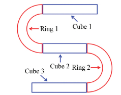 Fig.8 Geometrical configuration of an S-shaped CCM
 In this case, the size of the first solid cube is 26.1 mm, 6.0 mm, 6.0 mm, and the center coordinates of the first solid cube is -3.05 mm, -20.0 mm, 0 mm in the x, y, and z directions, respectively. The size of the second solid cube is 20.0 mm, 6.0 mm, 6.0 mm, and the center coordinates of the second solid cube is 0 mm, 0 mm, 0 mm in the x, y, and z directions, respectively. The size of the third solid cube is 26.1 mm, 6.0 mm, 6.0 mm, and the center coordinates of the third solid cube is 3.05 mm, 20.0 mm, 0 mm in the x, y, and z directions, respectively. The height of the first and second solid rings is 6.0 mm. The radius of the outer circle of the first and second solid rings is 13.0 mm. The radius of the inner circle of the first and second solid rings is 7.0 mm. The center coordinates of the first solid ring is -10.0 mm, 10.0 mm, 0 mm, and the center coordinates of the second solid ring is 10.0 mm, -10.0 mm, 0 mm in the x, y, and z directions, respectively.
In a similar manner, the phase A and the phase B of S-shaped CCM solid model based on TPMS cellular topology should be created as follows:
$\begin{array}{l}{\phi _{{\rm{solid\_TPMS\_A}}}} = \left( {{\phi _{{\rm{solid\_cube\_1}}}} \cap \phi _{{\rm{TPMS\_A}}}^{{\rm{solid\_cube\_1}}}} \right) \cup \\\;\;\;\;\;\;\;\;\;\;\left( {{\phi _{{\rm{solid\_cube\_2}}}} \cap \phi _{{\rm{TPMS\_A}}}^{{\rm{solid\_cube\_2}}}} \right) \cup \\\;\;\;\;\;\;\;\;\;\;\left( {{\phi _{{\rm{solid\_cube\_3}}}} \cap \phi _{{\rm{TPMS\_A}}}^{{\rm{solid\_cube\_3}}}} \right) \cup \\\;\;\;\;\;\;\;\;\;\;\left( {{\phi _{{\rm{solid\_ring\_1}}}} \cap \phi _{{\rm{TPMS\_A}}}^{{\rm{solid\_ring\_1}}}} \right) \cup \\\;\;\;\;\;\;\;\;\;\;\left( {{\phi _{{\rm{solid\_ring\_2}}}} \cap \phi _{{\rm{TPMS\_A}}}^{{\rm{solid\_ring\_2}}}} \right)\end{array}$ (12)
$\begin{array}{l}{\phi _{{\rm{solid\_TPMS\_B}}}} = \left( {{\phi _{{\rm{solid\_cube\_1}}}} \cap \phi _{{\rm{TPMS\_B}}}^{{\rm{solid\_cube\_1}}}} \right) \cup \\\;\;\;\;\;\;\;\;\;\;\left( {{\phi _{{\rm{solid\_cube\_2}}}} \cap \phi _{{\rm{TPMS\_B}}}^{{\rm{solid\_cube\_2}}}} \right) \cup \\\;\;\;\;\;\;\;\;\;\;\left( {{\phi _{{\rm{solid\_cube\_3}}}} \cap \phi _{{\rm{TPMS\_B}}}^{{\rm{solid\_cube\_3}}}} \right) \cup \\\;\;\;\;\;\;\;\;\;\;\left( {{\phi _{{\rm{solid\_ring\_1}}}} \cap \phi _{{\rm{TPMS\_B}}}^{{\rm{solid\_ring\_1}}}} \right) \cup \\\;\;\;\;\;\;\;\;\;\;\left( {{\phi _{{\rm{solid\_ring\_2}}}} \cap \phi _{{\rm{TPMS\_B}}}^{{\rm{solid\_ring\_2}}}} \right)\end{array}$ (13)
Fig. 9 shows an S-shaped CCM with P surface cellular topology. Through a set of simple functional operations of the VDFs with respect to TPMS-based internal cellular topology and the given external shape, a complete conformal CCM solid model was constructed and P surface cellular topology was truncated to adapt to the internal space of CCM. Theoretically, the number of constituents comprising a geometrical configuration of CCM is not limited. In order to show the generality and expansibility of the proposed design method, Eq.(11) can be generalized to the following equation:
${\phi _{{\rm{solid}}}} = \bigcup\limits_{a = 1}^N {\phi _{{\rm{solid}}}^a} $ (14)
Fig.9
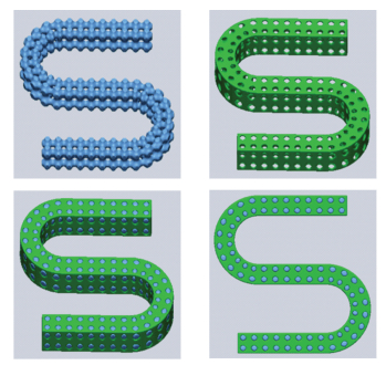 Fig.9 S-shaped CCM computational model with P surface cellular topology
 where N represents the number of constituents comprising a geometrical configuration of CCM, and ?solida represents the VDF of the a-th solid shape, and "
${\phi _{{\rm{solid\_TPMS\_A}}}} = \bigcup\limits_{a = 1}^N {\left( {\phi _{{\rm{solid}}}^a \cap \phi _{{\rm{TPMS\_A}}}^a} \right)} $ (15)
${\phi _{{\rm{solid\_TPMS\_B}}}} = \bigcup\limits_{a = 1}^N {\left( {\phi _{{\rm{solid}}}^a \cap \phi _{{\rm{TPMS\_B}}}^a} \right)} $ (16)
where ?TPMS_Aa and ?TPMS_Ba represent the a-th VDFs for the phase A and the phase B internal cellular topologies, respectively.
Various CCM models were constructed for a series of arbitrary complex geometrical configurations to prove the effectiveness and robustness of the proposed method. The proposed design procedure has been implemented based on MATLAB language on a desktop computer (Intel i5-4200H, 2.8 GHz, 8 GB).
Fig. 10 shows an O-shaped CCM solid model consisting of two cube solids and two ring solids, which was constructed by using Eqs. (14), (15), and (16). In the proposed design algorithm, the VDF can be simply modified, which corresponds to the needed combinations of the basic features, so that the internal cellular topologies can be successfully combined with the arbitrary geometrical configurations of CCM model in a consistent design framework.
Fig.10
 Fig.10 O-shaped CCM computational model with P surface cellular topology
 As can be seen from the experimental results, it was found again that the proposed design method can effectively and simply construct a variety of CCM models with high quality external shapes and intricate internal cellular topologies. So the proposed design method of this paper can be considered as one of candidates for an ideal CCM design methodology.
Table 1 illustrates that the computing time of the proposed design method is only a few hundred seconds. In order to study the effectiveness and practicality of the proposed method, several TPMS-based CCM prototypes were manufactured by a 3D printer, as shown in Fig. 11.
表 1
(phase A and phase B) Triangles
(phase A and phase B) Computing time(s)
T-shaped model(Fig. 4)A:65 648
B:87 696 A:131 440
B:175 88413
T-shaped model with P surface (Fig. 5(a))A:60 516
B:87 556 A:121 176
B:175 50413
T-shaped model with G surface(Fig. 5(b))A:90 800
B:90 780 A:182 184
B:182 14415
T-shaped model with P and IWP surface(Fig. 5(c))A:79 356
B:89 904 A:159 240
B:180 41214
T-shaped model with P and D surface(Fig. 5(d))A:83 540
B:96 732 A:167 656
B:194 260 15
T-shaped model varies in the number of cells with P surface (Fig. 5(e))A:90 580
B:113 052 A:181 944
B:227 732 13
T-shaped model varies in the number of cells with IWP surface (Fig. 5(f))A:134 628
B:125 692 A:273 200
B:254 524 16
Ring-shaped model with P surface (Fig. 6(a))A:977 464
B:1 309 592 A:1 955 312
B:2 620 336 537
Ring-shaped model with G surface (Fig. 6(b))A:1 402 678
B:1 386 574 A:2 806 796
B:2 774 540 631
Ring-shaped model with D surface (Fig. 6(c))A:1 665 496
B:1 665 432 A:3 333 936
B:3 333 840 795
Ring-shaped model with IWP surface(Fig. 6(d))A:1 579 004
B:1 438 968 A:3 160 600
B:2 879 760 693
Ring-shaped model varies in the parameters of basic feature with P surface (Fig. 6(e))A:2 603 628
B:2 915 124 A:5 220 248
B:5 853 096 905
Ring-shaped model varies in the parameters of basic feature with G surface (Fig. 6(f))A:1 094 254
B:1 090 686 A:2 190 620
B:2 183 468 513
Hybrid ring-shaped model with P surface (Fig. 7(a))A:1 872 232
B:1 747 832 A:3 752 976
B:3 505 072 951
Hybrid ring-shaped model with G surface(Fig. 7(b))A:104 168
B:989 944 A:2 210 560
B:1 982 128 831
S-shaped model with P surface(Fig. 9)A:102 604
B:137 172 A:205 864
B:276 372 272
O-shaped model with P surface(Fig. 10)A:77 868
B:104 156 A:156 248
B:209 848 230
Table 1 Computational results for various TPMS-based CCM models
Fig.11
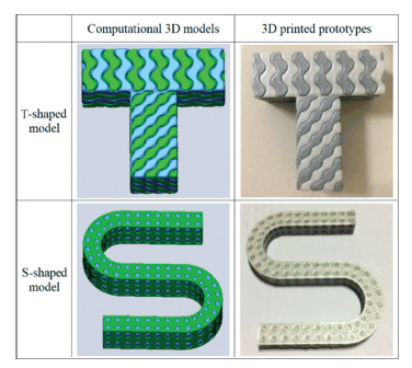 Fig.11 A set of CCMs manufactured by 3D printer
 In order to manufacture these polymer CCM prototypes, we used the Ultimaker 3 machine with dual-extrusion (https://ultimaker.com/en), which allows sophisticated dual material printing. The materials used were polylactic acid material for the phase A (silver metallic, 2.85 mm) and phase B (pearl white, 2.85 mm). In the printing process, the printing temperature was within 195-240 ℃, and the STL files were sliced to layers, each layer was 0.1 mm thickness. Due to wire drawing, the printed prototypes were not smooth enough outside, which is different from the ones designed by model. Design results and manufactured prototypes prove that the proposed CCM design method is feasible for producing multifunctional next generation CCMs.
4 Conclusion The arbitrarily-shaped complex CCM models can be designed and manufactured through the combination of computer aided design (CAD) and 3D printing technology. In this paper, we proposed a novel design methodology, which is a hybrid design method by combining the Boolean operation based on the VDF and the TPMS-based cellular topologies. This design algorithm enabled us to create various CCM computational models with complicated internal core structure and precise external surface faithful to the specific CCM shape while maintaining complete interconnectivity. Through the experimental design results, we can demonstrate that the proposed methodology can be applied to effectively and accurately produce a complete CCM solid model with the required internal core structure allowing optimization of its physical and mechanical properties.
This advanced design methodology has two distinct advantages. First, the proposed design method can effectively and accurately design a 3D complex CCM model with a specific purpose based on the required basic feature. Secondly, a variety of TPMS-based cellular topologies can be fully automatically generated to study the physical and mechanical properties of a CCM in a more systematic and scientific design framework.
Another significant advantage of the proposed method is that we can apply and extend this design method to more advanced research areas with unusual basic features required such as Bezier solid models, B-spline solid models, and NURBS solid models.
References
[1] Chawla N, Chawla K K. Microstructure-based modeling of the deformation behavior of particle reinforced metal matrix composites. Journal of Materials Science, 2006, 41(3): 913-925. DOI:10.1007/s10853-006-6572-1 (
 0)
0)[2] Kozera R, Bieliński J, Broda A, et al. Preparation of carbon fibres for aluminium composites. Advanced Materials Research, 2011, 264-265(11): 1487-1493. DOI:10.4028/www.scientific.net/AMR.264-265.1487 (
 0)
0)[3] Chawla N, Chawla K K. Metal-matrix composites in ground transportation. JOM, 2006, 58(11): 67-70. DOI:10.1007/s11837-006-0231-5 (
 0)
0)[4] Chabera P, Boczkowska A, Witek A, et al. Fabrication and characterization of composite materials based on porous ceramic preform infiltrated by elastomer. Bulletin of the Polish Academy of Sciences Technical Sciences, 2015, 63(1): 193-199. DOI:10.1515/bpasts-2015-0022 (
 0)
0)[5] Wang L, Lau J, Thomas E L, et al. Co-continuous composite materials for stiffness, strength, and energy dissipation. Advanced Materials, 2011, 23(13): 1524-1529. DOI:10.1002/adma.201003956 (
 0)
0)[6] Liu Y, Wang L. Enhanced stiffness, strength and energy absorption for co-continuous composites with liquid filler. Composite Structures, 2015, 128: 274-283. DOI:10.1016/j.compstruct.2015.03.064 (
 0)
0)[7] Torquato S, Donev A. Minimal surfaces and multifunctionality. Proceedings of the Royal Society A:Mathematical, Physical and Engineering Science, 2004, 460(2047): 1849-1856. DOI:10.1098/rspa.2003.1269 (
 0)
0)[8] Kinloch A J, Yuen M L, Jenkins S D. Thermoplastic-toughened epoxy polymers. Journal of Materials Science, 1994, 29(14): 3781-3790. DOI:10.1007/BF00357349 (
 0)
0)[9] Brooker R D, Kinloch A J, Taylor A C. The morphology and fracture properties of thermoplastic-toughened epoxy polymers. Journal of Adhesion, 2010, 86(7): 726-741. DOI:10.1080/00218464.2010.482415 (
 0)
0)[10] Carolan D, Chong H M, Ivankovic A, et al. Co-continuous polymer systems: A numerical investigation. Computational Materials Science, 2015, 98: 24-33. DOI:10.1016/j.commatsci.2014.10.039 (
 0)
0)[11] Kapfer S C, Hyde S T, Mecke K, et al. Minimal surface scaffold designs for tissue engineering. Biomaterials, 2011, 32(29): 6875-6882. DOI:10.1016/j.biomaterials.2011.06.012 (
 0)
0)[12] Abueidda D W, Bakir M, Abu Al-Rub R K A, et al. Mechanical properties of 3D printed polymeric cellular materials with triply periodic minimal surface architectures. Materials & Design, 2017, 122: 255-267. DOI:10.1016/j.matdes.2017.03.018 (
 0)
0)[13] Al-Ketan O, Assad M A, Abu Al-Rub R K A. Mechanical properties of periodic interpenetrating phase composites with novel architected microstructures. Composite Structures, 2017, 176: 9-19. DOI:10.1016/j.compstruct.2017.05.026 (
 0)
0)[14] Yoo D J. Porous scaffold design using the distance field and triply periodic minimal surface models. Biomaterials, 2011, 32(31): 7741-7754. DOI:10.1016/j.biomaterials.2011.07.019 (
 0)
0)[15] Yoo D J. Heterogeneous minimal surface porous scaffold design using the distance field and radial basis functions. Medical Engineering & Physics, 2012, 34(5): 625-639. DOI:10.1016/j.medengphy.2012.03.009 (
 0)
0)[16] Yoo D J. New paradigms in hierarchical porous scaffold design for tissue engineering. Material Science Engineering: C, 2013, 33(3): 1759-1772. DOI:10.1016/j.msec.2012.12.092 (
 0)
0)[17] Yoo D J. Advanced porous scaffold design using multi-void triply periodic minimal surface models with high surface area to volume ratio. International Journal of Precision Engineering and Manufacturing, 2014, 15(8): 1657-1666. DOI:10.1007/s12541-014-0516-5 (
 0)
0)[18] Yoo D J. Advanced projection image generation algorithm for fabrication of a tissue scaffold using volumetric distance field. International Journal of Precision Engineering and Manufacturing, 2014, 15(10): 2117-2126. DOI:10.1007/s12541-014-0571-y (
 0)
0)[19] Yoo D J. Recent trends and challenges in computer-aided design of additive manufacturing-based biomimetic scaffolds and bioartificial organs. International Journal of Precision Engineering and Manufacturing, 2014, 15(10): 2205-2217. DOI:10.1007/s12541-014-0583-7 (
 0)
0)[20] Yang N, Quan Z, Zhang D, et al. Multi-morphology transition hybridization CAD design of minimal surface porous structures for use in tissue engineering. Computer-Aided Design, 2014, 56(11): 11-21. DOI:10.1016/j.cad.2014.06.006 (
 0)
0)