Siyang Wang,Nai'an Liu
(State Key Laboratory on Integrated Services Networks, Xidian University, Xi’an 710071, China)
Abstract:
To generate high-frequency radio frequency (RF) vector signals, a vector signal generation method by optical frequency sextupling using a dual-parallel modulator is proposed. The method modulates vector signal on +3rd order optical sideband and local oscillator (LO) signal on -3rd order sideband using the intermodulation process in the DPMZM. After suppressing of the optical carrier and other sidebands through proper adjustment for modulator biases and modulation index, a frequency sextupled millimeter-wave vector signal can be generated after photodetection. The frequency sextupling will lower the bandwidth of the modulator, the local oscillator and the driving circuits. In addition, the phase of generated signal is not distorted after detection, and the power fading after fiber transmission can be avoided. In the simulation, a 500-MSym/s QPSK signal at 60 GHz is generated by 10-GHz drive signal. After travelling over fiber with length of 20/30/40-km, receiver power penalty keeps below 2.5 dB.
Key words: dual-parallel Mach-Zehnder modulator (DPMZM) frequency multiplication frequency up-conversion vector signal radio over fiber (RoF)
DOI:10.11916/j.issn.1005-9113.17094
Clc Number:TP92
Fund:
Siyang Wang, Nai'an Liu. Photonic Vector Signal Generation by Frequency Sextupling for Radio Over Fiber Systems[J]. Journal of Harbin Institute of Technology (New Series), 2019, 26(4): 18-24. DOI: 10.11916/j.issn.1005-9113.17094.

Fund Sponsored by the Programme of Introducing Talents of Discipline to Universities(Grant No. B08038) Corresponding author Siyang Wang, E-mail: 329488002@qq.com Article history Received: 2017-07-30
Contents Abstract Full text Figures/Tables PDF
Photonic Vector Signal Generation by Frequency Sextupling for Radio Over Fiber Systems
Siyang Wang

 , Nai'an Liu
 State Key Laboratory on Integrated Services Networks, Xidian University, Xi'an 710071, China
Received: 2017-07-30
Sponsored by the Programme of Introducing Talents of Discipline to Universities(Grant No. B08038)
Corresponding author: Siyang Wang, E-mail: 329488002@qq.com
Abstract: To generate high-frequency radio frequency (RF) vector signals, a vector signal generation method by optical frequency sextupling using a dual-parallel modulator is proposed. The method modulates vector signal on +3rd order optical sideband and local oscillator (LO) signal on -3rd order sideband using the intermodulation process in the DPMZM. After suppressing of the optical carrier and other sidebands through proper adjustment for modulator biases and modulation index, a frequency sextupled millimeter-wave vector signal can be generated after photodetection. The frequency sextupling will lower the bandwidth of the modulator, the local oscillator and the driving circuits. In addition, the phase of generated signal is not distorted after detection, and the power fading after fiber transmission can be avoided. In the simulation, a 500-MSym/s QPSK signal at 60 GHz is generated by 10-GHz drive signal. After travelling over fiber with length of 20/30/40-km, receiver power penalty keeps below 2.5 dB.
Keywords: dual-parallel Mach-Zehnder modulator (DPMZM) frequency multiplication frequency up-conversion vector signal radio over fiber (RoF)
1 Introduction The future broadband wireless communication systems are driving the operating spectrum to millimeter-wave[1-3], such as the 60 GHz frequency band. Because of large bandwidth and low loss features, radio over fiber (RoF) technologies have shown great potential in future millimeter-wave applications. For an RoF system, the bandwidth of the modulator, the local oscillator (LO), and the driving circuits can be reduced by optical frequency multiplication techniques[4-12]. As the electrical signals in the above schemes are modulated on each optical sideband, the amplitudes and phases of the electrical signals will be also multiplied after direct detection, causing constellation overlapping[13]. Therefore, they are not suitable for vector signal formats like quadrature amplitude modulation (QAM), which is frequently used in BWA applications.
Several photonic vector signal generation schemes with frequency multiplication have been proposed, by Lin CT et al.[14-15], to avoid the constellation overlapping problem. In Refs.[14] and [15], the microwave vector signal is obtained using a dual-parallel Mach-Zehnder modulator (DPMZM). In the last several years, photonic vector signal generation schemes for W-band applications are intensively studied and reported[16-18]. However, only frequency doubling can be achieved in these schemes. For a W-band application at 88 GHz, for example, it may be a limitation for the electrical and optical components to generate and handle the drive signal at 44 GHz. In Ref.[13], a frequency-quadruped vector signal generator by a DPMZM is proposed. The frequency quadrupled vector signal can be also generated using a single MZM, as described in Ref.[19]. However, a complicated wavelength selective switch is required. Two schemes described in Refs.[1] and [20] can be used to generate 60 GHz vector signal by frequency quintupling and sextupling, respectively. However, two cascaded DPMZMs are required in both of the two schemes, thus increasing the system complexity and instability. Previously, an optical vector signal generator by frequency quadrupling based on a DPMZM is proposed in Ref.[21]. Photonic vector signal generation methods with frequency octupling are also reported in Refs.[22] and [23]. High-frequency signals at W band can be easily generated, but the WSS is also in need. As it is difficult to realize quick tuning of the WSS, the reported schemes based on WSS face the problem of poor frequency tunability.
Herein, a photonic vector signal generation scheme by frequency sextupling based on a DPMZM is proposed. By tuning the bias of DPMZM and the modulation index (MI) of drive signal, a frequency sextupled millimeter-wave vector signal can be generated after direct detection, and the phase is preserved to avoid the constellation overlapping problem. In addition, other sidebands and the optical carrier are suppressed to avoid power fading caused by the fiber dispersion. In the proposed scheme, frequency sextupling is achieved using only a DPMZM, which reduces the bandwidths of the modulator, LO and the driving circuits as compared with other reported schemes. As compared with the schemes previously reported, the proposed scheme may feature the advantages of simple structure, high frequency multiplication factor and good frequency tunability. In the simulation, a 60 GHz and 500-MSymbol/s QPSK signal is obtained using 10 GHz drive signal. After travelling over single mode fiber (SMF) with length of 20/30/40 km, receiver power penalty keeps below 2.5 dB.
2 Principle The proposed system can be seen from Fig. 1. A DPMZM with parallel sub-MZMs (a-MZM, b-MZM) and a main modulator (c-MZM) is employed. The two sub-MZMs with half-wave voltage of Vπ are both working at the minimum point.
Fig.1
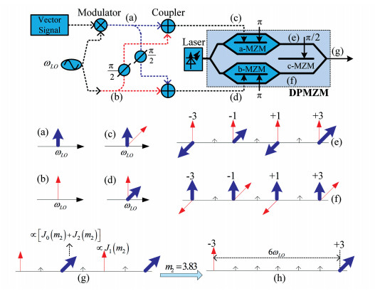 (a) Spectra of QPSK RF signal; (b) Spectra of LO signal; (c) Spectra of electrical signal driving a-MZM; (d) Spectra of electrical signal driving b-MZM; (e) Spectra of optical signal after a-MZM; (f) Spectra of optical signal after b-MZM; (g) Spectra of optical signal after DPMZM; (h) Spectra of optical signal when m2=3.83Fig.1 Proposed vector signal generator by frequency sextupling based on a DPMZM
 The optical signal after the LD is
$E_{i n}(t)=E_{0} \exp \left({\rm j} \omega_{c} t\right)$
When an RF signal expressed as Vsin(ωt) is injected into the MZM, the output optical signal is[24]
$\begin{aligned} \frac{1}{2} E_{i n}(t) &\left\{\exp \left[{\rm j} \frac{\mathsf{π} V}{2 V_{\mathsf{π}}} \sin (\omega t)\right] \exp \left({\rm j} \frac{\theta}{2}\right)+\right.\\ &\left.\exp \left[-{\rm j} \frac{\mathsf{π} V}{2 V_{\mathsf{π}}} \sin (\omega t)\right] \exp \left(-{\rm j} \frac{\theta}{2}\right)\right\} \end{aligned}$
where θ is the bias phase shift. When the MZM is in the minimum point, θ=π, and when it is in the quadrature point, θ=π/2.
We assume that the QPSK signal has the center frequency of ω0 and the phase information of θ(t), and its spectrum is denoted by Fig. 1(a). An LO, VLOsin (ωLOt), as shown in Fig. 1(b), is halved, with one modulated by QPSK signal. The generated QPSK RF signal is:
$\begin{aligned} V_{\mathrm{RF}}(t) &\left\{\sin \left[\left(\omega_{\mathrm{LO}}+\omega_{0}\right) t+\theta(t)\right]+\right.\\ &\left.\sin \left[\left(\omega_{\mathrm{LO}}-\omega_{0}\right) t-\theta(t)\right]\right\} \end{aligned}$
where VRF(t) contains amplitude information of QPSK RF signal. The vector and LO signals are followed by electrical power dividers, phase shifters and couplers, as described in Fig. 1. Then two hybrid signals, denoted by Fig. 1(c) and (d) respectively, are injected to a-MZM and b-MZM. Using the following Jacobi-Anger identity[25]
$\exp ({\rm{j}}m\sin x) = \sum\limits_{n = - \infty }^\infty {{J_n}} (m)\exp ({\rm{j}}nx)$
The optical signal after a-MZM is expressed as follows[26]:
$\begin{aligned} E_{a}(t)=& \frac{E_{0}}{2 \sqrt{2}} \exp \left(\mathrm{j} \omega_{c} t\right)\cdot \\ & \sum\limits_{m=-\infty}^{\infty} \sum\limits_{n=-\infty}^{\infty} \sum\limits_{p=-\infty}^{\infty} J_{m}\left(m_{1}\right) J_{n}\left(m_{1}\right) J_{p}\left(m_{2}\right)\cdot \\ & \exp \left\{\mathrm{j}\left[(m+n+p) \omega_{L O}+(m-n) \omega_{0}\right] t+\right.\\ &\left.\mathrm{j}(p+1) \frac{\mathsf{π}}{2}+\mathrm{j}(m-n) \theta(t)\right\}\cdot \\ &\left[-1+(-1)^{m+n+p}\right] \end{aligned}$
where
$\begin{array}{c}{m_{1}=\max \left\{\mathsf{π} V_{R F}(t) /\left(2 V_{\mathsf{π}}\right)\right\}} \\ {m_{2}=\mathsf{π} V_{L O} /\left(2 V_{\mathsf{π}}\right)}\end{array}$
are the RF/LO MIs, respectively. Jn(·) is nth-order Bessel function. Considering that m1is usually small, the Bessel functions are negligible for n> 1. In order to simplify the discussion, only the sidebands below ±3rd order are analyzed and depicted in Fig. 1(e). As we can see, both the LO and the vector signal are modulated on the ±3rd order optical sidebands. The ±3rd order sidebands modulated by LO signal are generated from the 3rd harmonic of LO drive signal, and ±3rd order vector sidebands are primarily generated from the intermodulation of the fundamental vector signal and 2nd LO signal. 3rd harmonics of vector signal are negligible because of the small MI of vector signal, so there is little distortion in the vector information of the ±3rd order sidebands.
Similarly, the output of b-MZM is:
$\begin{aligned} E_{b}(t)=& \frac{E_{0}}{2 \sqrt{2}} \exp \left(\mathrm{j} \omega_{c} t\right)\cdot \\ & \sum\limits_{m=-\infty}^{\infty} \sum\limits_{n=-\infty}^{\infty} \sum\limits_{p=-\infty}^{\infty} J_{m}\left(m_{1}\right) J_{n}\left(m_{1}\right) J_{p}\left(m_{2}\right)\cdot \\ & \exp \left\{\mathrm{j}\left[(m+n+p) \omega_{L O}+(m-n) \omega_{0}\right] t+\right.\\ &\left.\mathrm{j}(m+n+1) \frac{\mathsf{π}}{2}+\mathrm{j}(m-n) \theta(t)\right\}\cdot \\ &\left[-1+(-1)^{m+n+p}\right] \end{aligned}$
The optical sidebands below ±3rd order are depicted in Fig. 1(f). The c-MZM is in the quadrature point. The signal after DPMZM is:
$\begin{aligned} E_{c}(t)=& E_{a}(t)+E_{b}(t) \cdot \exp (\mathrm{j} \mathsf{π} / 2)=\\ & \frac{E_{0}}{4} \exp \left({\rm j} \omega_{c} t\right)\cdot \\ & \sum\limits_{m=-\infty}^{\infty} \sum\limits_{n=-\infty}^{\infty} \sum\limits_{p=-\infty}^{\infty} J_{m}\left(m_{1}\right) J_{n}\left(m_{1}\right) J_{p}\left(m_{2}\right)\cdot \\ & \exp \left\{\mathrm{j}\left[(m+n+p) \omega_{L O}+(m-n) \omega_{0}\right] t+\right.\\ &\mathrm{j}(m-n) \theta(t)\} \cdot\left[-1+(-1)^{m+n+p}\right] \cdot \\ &\left[\mathrm{j}^{p+1}+\mathrm{j}^{m+n+2}\right] \end{aligned}$ (1)
From Figs. 1(e)-(g), we can see that the -3rd optical sidebands modulated by the vector signals in the two arms will cancel each other out when c-MZM is in the quadrature point. Similarly, the +3rd order sidebands modulated by the LO signals will also cancel each other out at the output of DPMZM.
The characteristics of Bessel function curves are described in Fig. 2. To eliminate +1st sideband, LO MI is set as m2=3.83 to achieve J1(m2)=0. In addition, when m2=3.83, we can get J2(m2)≈-J0(m2), and then the -1st order sideband can be also canceled, as shown in Fig. 1(h).
Fig.2
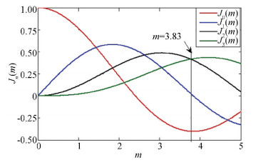 Fig.2 Bessel functions
 The expression in Eq.(1) can be approximately rewritten as:
$\begin{aligned} E_{c}(t) & \approx 2 E_{0} \exp \left({\rm j} \omega_{c} t\right) \cdot\left\{J_{3}\left(m_{2}\right)\right.\cdot\\ & \exp \left(-\mathrm{j} 3 \omega_{L 0} t\right)+\\& {J_{1}\left(m_{1}\right)\left[J_{2}\left(m_{2}\right)+J_{4}\left(m_{2}\right)\right]}\cdot \\ &{\left[\exp \left({\rm j}\left(3 \omega_{L O}+\omega_{0}\right) t+\right.\right.} \\ &{\left.\mathrm{j} \theta(t)+\mathrm{j} \frac{\mathsf{π}}{2}\right)+\exp \left(\mathrm{j}\left(3 \omega_{L O}-\right.\right.} \\ &{\left.\left.\left.\left.\omega_{0}\right) t-\mathrm{j} \theta(t)+\mathrm{j} \frac{\mathsf{π}}{2}\right)\right]\right\}}\end{aligned}$
The generated optical signal consisting of two-tone lightwave is shown in Fig. 1(h). It is then transmitted over an SMF. The transmission function of the SMF with length of L is[27]
$H({\rm j} \omega)=\exp \left(-\frac{1}{2} \alpha L+{\rm j} \beta L\right)$
where α and β are fiber attenuation and propagation constant, and
$\begin{aligned} \beta=& \beta\left(\omega_{c}\right)+\beta_{1}\left(\omega_{c}\right)\left(\omega-\omega_{c}\right)+\\ & \beta_{2}\left(\omega_{c}\right)\left(\omega-\omega_{c}\right)^{2} / 2+\ldots \end{aligned}$
where β1(ωc) and β2(ωc) are the first- and second-order derivatives of β. Neglecting higher order derivatives of β, optical signal after SMF is:
$\begin{aligned} E_{c}(t) & \approx 2 E_{0} \exp \left(-\frac{1}{2} \alpha L\right) \cdot \exp \left[{\rm j} \omega_{c} t+{\rm j} \beta\left(\omega_{c}\right) L\right] \cdot\\ &\left\{J_{3}\left(m_{2}\right) \cdot \exp \left[-\mathrm{j} 3 \omega_{L o} t-3 \mathrm{j} \omega_{L O} \beta_{1}\left(\omega_{c}\right) L+\right.\right.\\&\left.\frac{1}{2} \mathrm{j}\left(3 \omega_{L O}\right)^{2} \beta_{2}\left(\omega_{c}\right) L\right]+J_{1}\left(m_{1}\right)\left[J_{2}\left(m_{2}\right)+\right.\\&\left.J_{4}\left(m_{2}\right)\right] \cdot\left[\exp \left(\mathrm{j}\left(3 \omega_{L O}+\omega_{0}\right)_{t}+\right.\right.\\ &\mathrm{j} \theta(t)+\mathrm{j} \frac{\mathsf{π}}{2}+\mathrm{j}\left(3 \omega_{L O}+\omega_{0}\right) \beta_{1}\left(\omega_{c}\right) L+\\ &\left.0.5 \mathrm{j}\left(3 \omega_{L O}+\omega_{0}\right)^{2} \beta_{2}\left(\omega_{c}\right) L\right)+\\ & \exp \left(3 \omega_{L O}-\omega_{0}\right) t-\mathrm{j} \theta(t)+\mathrm{j} \frac{\mathsf{π}}{2}+\\ & \mathrm{j}\left(3 \omega_{L O}-\omega_{0}\right) \beta_{1}\left(\omega_{c}\right) L+\\&\left.\left.\left.0.5 \mathrm{j}\left(3 \omega_{L O}-\omega_{0}\right)^{2} \beta_{2}\left(\omega_{c}\right) L\right)\right]\right\} \end{aligned}$
After square-law detection by a photodetector (PD), sextupling vector signal is obtained:
$\begin{aligned} I_{6 \omega_{R F}}(t)=& 4 R \exp (-\alpha L) J_{1}\left(m_{1}\right) J_{3}\left(m_{2}\right)\cdot \\ &\left[J_{2}\left(m_{2}\right)+J_{4}\left(m_{2}\right)\right] E_{0}^{2} \cdot\left\{\exp \left(\mathrm{j}\left(6 \omega_{L O}+\right.\right.\right.\\&\left.\omega_{0}\right)\left[t+\beta_{1}\left(\omega_{c}\right) L\right]+\mathrm{j} \theta(t)+\mathrm{j} \frac{\mathsf{π}}{2}+\\&\left.0.5 \mathrm{j}\left(\omega_{0}^{2}+6 \omega_{L O} \omega_{0}\right) \beta_{2}\left(\omega_{c}\right) L\right)+\\ &\exp \left(\mathrm{j}\left(6 \omega_{L O}-\omega_{0}\right)\left[t+\beta_{1}\left(\omega_{c}\right) L\right]-\right.\\ &\left.\left.\mathrm{j} \theta(t)+\mathrm{j} \mathsf{π} / 2-0.5 \mathrm{j}\left(\omega_{0}^{2}-6 \omega_{L O} \omega_{0}\right) \beta_{2}\left(\omega_{c}\right) L\right)\right\} \end{aligned}$
where R is responsivity. The current intensity is only related to the inherent insertion loss of the fiber, and is independent of the fiber dispersion. In the traditional double sideband (DSB) modulation, the vector signal is generated from two or more beating terms and thus will suffer power fading problem[28]. In the proposed scheme, however, the millimeter-wave vector signal is generated from only one beating term of the two 3rd-order optical sidebands and thus can avoid power fading. The group delay contributed by β1(ωc)L will not distort vector phase. The fiber dispersion contributed by 0.5(ω02±6ωLOω0)β2(ωc)L will distort the wideband vector signal, which cannot be avoided inherently, only if proper dispersion compensation is carried out.
3 Simulation and Result Analysis Fig. 3 describes simulation setup using VPItransmissionMaker. The parameters of the components are set according to the data sheets of actual commercial devices. A single-frequency optical carrier is generated from an LD. The two sub-MZMs are working in the minimum points. The modulator extinction ratio is set to 35 dB and the insertion loss is 4 dB. A 10 GHz LO is split into two parts equally and one part carries a 500-MSymbol/s QPSK signal from a vector signal generator (VSG) in the VPI. The length of the PRBS sequences used for the I/Q signals is 214-1. Both the 10 GHz QPSK RF and LO signals are split using a 90° hybrid coupler. The two upper path signals and the two lower path signals are combined by a coupler respectively. The two combined signals are amplified respectively to achieve the MI of LO at m2=3.83. The optical signal after b-MZM is first processed by a π/2 optical phase shifter that acts as the dc bias of c-MZM in DPMZM, and then combined together with the optical output from a-MZM.
Fig.3
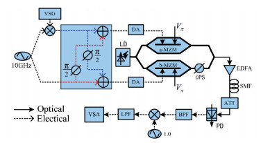 Fig.3 Simulation setup
 Then an optical signal with its spectrum consisted of vector signal on +3rd sideband (193.1 THz+30 GHz) and a -3rd order optical sideband (193.1 THz-30 GHz) is obtained, which can be found from Fig. 4(a). An erbium-doped fiber amplifier (EDFA) is applied to amplify the power to 0 dBm before transmission over an SMF. After a high speed positive-intrinsic-negative (PIN) PD, a 60 GHz QPSK signal is generated in Fig. 4(b).
Fig.4
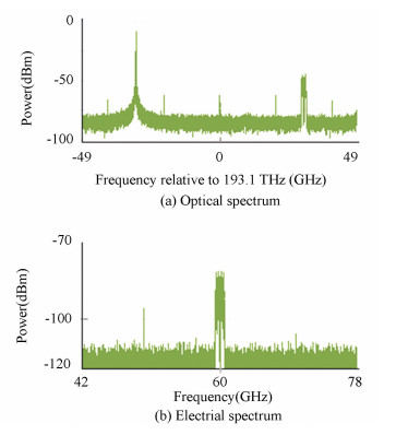 Fig.4 Spectra of optical signal output from DPMZM, and 60-GHz QPSK signal after a direct detection
 The resolutions of above two spectra are both 250 MHz. After down-conversion, a vector signal analyzer (VSA) is applied to demodulate the QPSK signal, to show constellation diagram, and to evaluate the error vector magnitude (EVM)[29]:
$E V M=\sqrt{\sum\limits_{i=1}^{N}\left|d_{r}-d_{i}\right|^{2} / N / |} d_{\max } |$
where dr and di denote real and ideal symbols. N denotes total symbol number. dmax denotes maximum symbol vector.
The optimal RF MI (m1) is also studied. Fig. 5 depicts the EVM performance at back-to-back (BTB) as a function of m1. It shows that the EVM is minimum when m1=0.7. When m1 is below 0.7, the power of the detected RF signal increases linearly with m1, and so the EVM decreases with m1. When m1>0.7, the nonlinearity of the link is dominant, EVM will increase due to the significant intermodulation distortions.
Fig.5
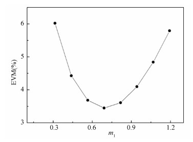 Fig.5 EVM versus the modulation index of the QPSK modulated 10-GHz drive signal
 An SMF with 17-ps/nm/km dispersion is used to evaluate system performance after fiber transmission. As analyzed in Section 2, the millimeter-wave vector signal in this scheme is generated from only one beating term of high-purity two-tone light waves, so the chromatic dispersion induced power fading issue can be avoided. The power of the 60 GHz QPSK signal after PD with different fiber length is measured and drawn in Fig. 6. Electrical power of received QPSK signal remains rather flat at different transmission distance.
Fig.6
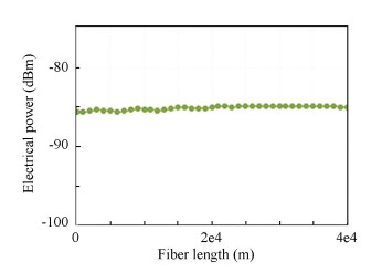 Fig.6 Electrical power as a function of fiber length
 The bit error rate (BER) is plotted in Fig. 7. When at BTB, bit error is mainly caused by the system noise, including RIN, shot noise and signal-spontaneous beat noise from EDFA[30]. After fiber transmission, the chromatic dispersion will also lead to bit error of the received 500-Msymbol/s QPSK signal. However, as shown in Fig. 7, with a BER at 10-9, the received power increases is only 0.5, 1, and 2.5 dB with 20 km, 30 km, and 40 km SMF, which shows a fine transmission performance of generated photonic vector signal. Fig. 8 draws the constellation diagrams, and no constellation overlapping is observed.
Fig.7
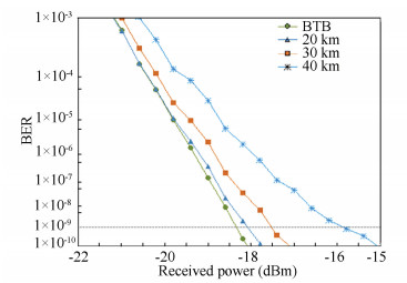 Fig.7 BER with different length
 Fig.8
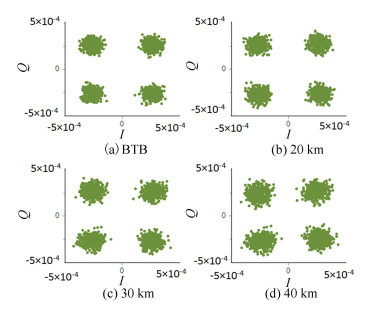 Fig.8 Constellation diagrams after fiber transmission
 4 Conclusions In this paper, a frequency sextupled photonic vector signal generator is proposed and analyzed. In the proposed DPMZM based scheme, the dc biases of the modulators and the MI of the LO signal are properly adjusted to suppress undesired components, and the optimal MI of the vector signal modulated drive signal is also investigated. A 60-GHz vector signal is generated in simulation. With 20/30/40-km fiber transmission, power penalty is below 2.5 dB. This proposed scheme has simple structure, good transmission performance, and the frequency multiplication factor is larger than any of the vector signal frequency up-conversion schemes with one modulator previously reported, which can significantly lower the bandwidths of the modulator, LO and the driver amplifier, indicating that it may be useful in a 60-GHz RoF system.
References
[1] Shih P T, Lin C T, Jiang W J, et al. Transmission of 20-Gb/s OFDM signals occupying 7-GHz license-free band at 60 GHz using a RoF system employing frequency sextupling optical up-conversion. Opt. Express, 2010, 18(12): 12748-12755. DOI:10.1364/oe.18.012748 (
 0)
0)[2] Xiao J, Li X, Xu Y, et al. W-band OFDM photonic vector signal generation employing a single Mach-Zehnder modulator and precoding. Opt. Express, 2015, 23(18): 24029-24034. DOI:10.1364/oe.23.024029 (
 0)
0)[3] Novak D, Waterhouse R B, Nirmalathas A, et al. Radio-over-fiber technologies for emerging wireless systems. IEEE J. Quantum Electron., 2015, 52(1): 1-11. DOI:10.1109/JQE.2015.2504107 (
 0)
0)[4] Li W, Yao J. Investigation of photonically assisted microwave frequency multiplication based on external modulation. IEEE Trans. Microw. Theory Tech., 2010, 58(11): 3259-3268. DOI:10.1109/TMTT.2010.2075671 (
 0)
0)[5] Mohamed M, Zhang X, Hraimel B, et al. Frequency sixupler for millimeter-wave over fiber systems. Opt. Express, 2008, 16(14): 10141-10151. DOI:10.1364/oe.16.010141 (
 0)
0)[6] Yu J, Jia Z, Yi L, et al. Optical millimeter-wave generation or up-conversion using external modulators. IEEE Photon. Technol. Lett., 2006, 18(1): 265-267. DOI:10.1109/lpt.2005.862006 (
 0)
0)[7] Chi H, Yao J. Frequency quadrupling and upconversion in a radio over fiber link. J. Lightw. Technol., 2008, 26(15): 2706-2711. DOI:10.1109/jlt.2008.927613 (
 0)
0)[8] Zhu D, Pan S, Cai S, et al. High-performance photonic microwave downconverter based on a frequency-doubling optoelectronic oscillator. J. Lightw. Technol., 2012, 30(18): 3036-3042. DOI:10.1109/jlt.2012.2211096 (
 0)
0)[9] Shi P, Yu S, Li Z, et al. A novel frequency sextupling scheme for optical mm-wave generation utilizing an integrated dual-parallel Mach-Zehnder modulator. Opt. Commun., 2010, 283(19): 3667-3672. DOI:10.1016/j.optcom.2010.05.021 (
 0)
0)[10] Chen Y, Wen A, Shang L. Analysis of an optical mm-wave generation scheme with frequency octupling using two cascaded Mach-Zehnder modulators. Opt. Commun., 2010, 283(24): 4933-4941. DOI:10.1016/j.optcom.2010.07.046 (
 0)
0)[11] Yin X, Wen A, Chen Y, et al. Studies in an optical millimeter-wave generation scheme via two parallel dual-parallel Mach-Zehnder modulators. Mod. Opt., 2011, 58(8): 665-673. DOI:10.1080/09500340.2011.565375 (
 0)
0)[12] Zhang Y, Pan S. Experimental demonstration of frequency-octupled millimeter-wave signal generation based on a dual-parallel Mach-Zehnder modulator. 2012 IEEE MTT-S International Microwave Workshop Series on Millimeter Wave Wireless Technology and Applications (IMWS). Piscataway: IEEE, 2012. DOI: 10.1109/imws2.2012.6338202. (
 0)
0)[13] Lin C T, Shih P T, Jiang J W, et al. Photonic vector signal generation at microwave/millimeter-wave bands employing an optical frequency quadrupling scheme. Opt. Lett., 2009, 34(14): 2171-2173. DOI:10.1364/ol.34.002171 (
 0)
0)[14] Lin C T, Dai S P, Chen J, et al. A novel direct detection microwave photonic vector modulation scheme for radio-over-fiber system. IEEE Photon. Technol. Lett., 2008, 20(13): 1106-1108. DOI:10.1109/lpt.2008.924176 (
 0)
0)[15] Lin C T, Shih P T, Chen Y H, et al. Experimental demonstration of 10-Gb/s OFDM-QPSK signal at 60 GHz using frequency-doubling and tandem SSB modulation. In Optical Fiber Communication Conference, Optical Society of America.San Diego, 2009. DOI: 10.1364/ofc.2009.omv7. (
 0)
0)[16] Zhao L, Yu J, Chen L, et al. 16QAM vector millimeter-wave signal generation based on phase modulator with photonic frequency doubling and precoding. IEEE Photonics Journal, 2016, 8(2): 1-8. DOI:10.1109/jphot.2016.2520821 (
 0)
0)[17] Li R, Li W, Chen X, et al. Millimeter-wave vector signal generation based on a Bi-Directional use of a polarization modulator in a Sagnac loop. Journal of Lightwave Technology, 2015, 33(1): 251-257. DOI:10.1109/jlt.2014.2379473 (
 0)
0)[18] Wang Y, Chien H C, Guo H, et al. Photonic RF vector signal generation with enhanced spectral efficiency using precoded double single-sideband modulation. Optics Letters, 2016, 41(11): 2557-2560. DOI:10.1364/ol.41.002557 (
 0)
0)[19] Li X, Xiao J, Yu J. W-band vector millimeter-wave signal generation based on phase modulator with photonic frequency quadrupling and precoding. Journal of Lightwave Technology, 2017, 35(13): 2548-2558. DOI:10.1109/JLT.2017.2696885 (
 0)
0)[20] Lin C T, Wong E Z, Jiang W J, et al. 28-Gb/s 16-QAM OFDM radio-over-fiber system within 7-GHz license-free band at 60 GHz employing all-optical up-conversion. In Conference on Lasers and Electro-Optics, Optical Society of America. 2009.paper CPDA8. DOI: 10.1364/cleo.2009.cpda8. (
 0)
0)[21] Li M, Wen A, Chen Y, et al. An optical millimeter-wave vector signal generation scheme by frequency quadrupling. Opt. Commun., 2012, 285(24): 5429-5432. DOI:10.1016/j.optcom.2012.07.096 (
 0)
0)[22] Li X, Zhang J, Xiao J, et al. W-Band 8QAM vector signal generation by MZM-Based photonic frequency octupling. IEEE Photonics Technology Letters, 2015, 27(12): 1257-1260. DOI:10.1109/LPT.2015.2415999 (
 0)
0)[23] Xiao J, Zhang Z, Li X, et al. High-frequency photonic vector signal generation employing a single phase modulator. IEEE Photonics Journal, 2015, 7(2): 1-6. (
 0)
0)[24] Cox C. Analog Optical Links: Theory and Practice. Cambridge: Cambridge University Press, 2004. (
 0)
0)[25] Colton D, Kress R. Inverse acoustic and electromagnetic scattering theory. Springer-Verlag, 1992. 140-145. DOI: 10.1007/978-3-662-02835-3_5. (
 0)
0)[26] Li W, Yao J. Investigation of photonically assisted microwave frequency multiplication based on external modulation. IEEE Transactions on Microwave Theory & Techniques, 2010, 58(11): 3259-3268. DOI:10.1109/tmtt.2010.2075671 (
 0)
0)[27] Yao J, Zeng F, Wang Q. Photonic generation of ultrawideband signal. Journal of Lightwave Technology, 2007, 25(11): 3219-3235. DOI:10.1109/JLT.2007.906820 (
 0)
0)[28] Gao Y, Wen A, Chen Y, et al. An analog photonic link with compensation of dispersion-induced power fading. IEEE Photonics Technology Letters, 2015, 27(12): 1301-1304. DOI:10.1109/LPT.2015.2421271 (
 0)
0)[29] Peng W R, Wu X, Arbab V R, et al. Experimental demonstration of a coherently modulated and directly detected optical OFDM system using an RF-tone insertion. Conference on Optical Fiber Communication Conf. (OFC), Piscataway: IEEE, 2008.paper OMU1. DOI: 10.1109/ofc.2008.4528410. (
 0)
0)[30] Middleton C, Borbath M, Wyatt J, et al. Measurement of SFDR and noise in EDF amplified analog RF links using all-optical down-conversion and balanced receivers. Proc. SPIE 6975, Enabling Photonics Technologies for Defense, Security, and Aerospace Applications Ⅳ. 2008.paper 69750Q. DOI: 10.1117/12.774152. (
 0)
0)