Yongyao Yan1,2, Wei Liu1,Changxiang Yan1,Jinjiang Fu1,2
(1.Changchun Institute of Optics, Fine Mechanics and Physics, Chinese Academy of Science, Jilin 130033, China;2. University of Chinese Academy of Sciences, Beijing 100049,China)
Abstract:
The purpose of this thesis is to derive the flexibility formula of the corner-filleted flexure hinge easily and conveniently and use it to design a micro-rotation compliant mechanism. Firstly, we get the corner-filleted flexure hinge flexibility formula by methods of symmetry transformation and coordinates translation. The correctness of this formula is validated on the basis of the finite element method and under the premise that the effects of shear stress are taken into consideration. Then a micro-rotation compliant mechanism is designed in accordance with the corner-filleted flexure hinge, and the deduction and analysis of its working moment/rigidity are conducted. Moreover, this theoretical formula is proved to be accurate and reliable through the finite element analysis and the experimental verification, based on which the structural design and optimization can be made on the rotating part of a micro adjustment device.The results illustrate that designing and optimizing the structures by the analysis model is convenient and reliable so that complicated 3D modeling and finite element analysis are not needed.
Key words: flexure hinge corner-filleted compliant mechanism rigidity optimization analysis model
DOI:10.11916/j.issn.1005-9113.15372
Clc Number:TH122
Fund:
Yongyao Yan, Wei Liu, Changxiang Yan, Jinjiang Fu. Analysis of the Micro-Rotation Compliant Mechanism Based on the Corner-Filleted Flexure Hinges[J]. Journal of Harbin Institute of Technology, 2017, 24(5): 71-81. DOI: 10.11916/j.issn.1005-9113.15372.

Fund Sponsored by the National High-tech R & D Progrom (Grant No.2011AA12A103) and the Equipment Development Fund (Grant No.08001SA050) Corresponding author Yongyao Yan, E-mail: 512190699@qq.com Article history Received: 2015-12-24
Contents Abstract Full text Figures/Tables PDF
Analysis of the Micro-Rotation Compliant Mechanism Based on the Corner-Filleted Flexure Hinges
Yongyao Yan1,2

 , Wei Liu1, Changxiang Yan1, Jinjiang Fu1,2
 1. Changchun Institute of Optics, Fine Mechanics and Physics, Chinese Academy of Science, Jilin 130033, China;
2. University of Chinese Academy of Sciences, Beijing 100049, China
Received: 2015-12-24
Fund: Sponsored by the National High-tech R & D Progrom (Grant No.2011AA12A103) and the Equipment Development Fund (Grant No.08001SA050)
Corresponding author: Yongyao Yan, E-mail: 512190699@qq.com
Abstract: The purpose of this thesis is to derive the flexibility formula of the corner-filleted flexure hinge easily and conveniently and use it to design a micro-rotation compliant mechanism. Firstly, we get the corner-filleted flexure hinge flexibility formula by methods of symmetry transformation and coordinates translation. The correctness of this formula is validated on the basis of the finite element method and under the premise that the effects of shear stress are taken into consideration. Then a micro-rotation compliant mechanism is designed in accordance with the corner-filleted flexure hinge, and the deduction and analysis of its working moment/rigidity are conducted. Moreover, this theoretical formula is proved to be accurate and reliable through the finite element analysis and the experimental verification, based on which the structural design and optimization can be made on the rotating part of a micro adjustment device.The results illustrate that designing and optimizing the structures by the analysis model is convenient and reliable so that complicated 3D modeling and finite element analysis are not needed.
Key words: flexure hinge corner-filleted compliant mechanism rigidity optimization analysis model
1 IntroductionA flexure hinge is composed of the intermediate elastic deformation units connecting the two rigid bodies together. Since its intermediate part is weak portion, the apparent elastic deformation can be observed under the pressure of force or torque. Accordingly, the relative motion between the two bodies will be achieved. In recent years, the flexible hinges have been brought into attention of the researchers in the fields of optics and structures due to its advantages of no wear, no mechanical friction, no assembly, simple processing and high kinematic accuracy. Its application is widely seen in various occasions that require the small-angular displacement and high-accuracy transmission, such as the electron scanning microscope[1], the micro-displacement worktable[2] and the ultra-precision machine tools[3]. Single flexure hinges are mainly classified into the flexure hinges, the concave flexure hinges and the mixed flexure hinges. Concave flexure hinges can be further divided into the arc, elliptical-arc, parabolic, hyperbolic, v-pattern and different mixed ones by the various types of the curve. The broadly-applicable corner-filleted flexure hinges are of great theoretical value due to the fact that they are the combination of motion scope and accuracy.
A lot of studies on flexure hinges have been performed by the scholars from home and abroad. In 1965, under the initial guidance of the Euler-Bernoulli beam theory, Paros and Weisbord [4]deduced a precise and approximate theoretical formula to calculate the compliance of circular flexure hinges; Wu[5] deduced an accurate and relatively simple one; Tian et al.[6]studied the v-pattern chamfer flexure hinges, etc; Lobontiu et al[7]. studied the elliptical-circular flexure hinges and the corner-filleted parabolic mixed flexure hinges[8]; Lin et al.[9] studied the performance of mixed asymmetry flexure hinges one sided by a hyperbola and the other by a chamfer. Directing at the corner-filleted flexure hinge, Xu et al.[10]analyzed the rotation precision of the circular, corner-filleted and elliptical flexure hinges using the finite element method in 1996 and found that the corner-filleted ones were the best. Lobontiu et al.[11] researched corner-filleted flexure hinges by Castigliano's theorem and introduced a new class of two-axis flexure hinges including the corner-filleted flexure spherical hinge[12]; Chen et al.[13] pulled corner-filleted flexure hinge's expressions of bending rigidity, rotation accuracy and maximum stress by mechanics of materials; Meng et al.[14]presented a new analysis approach for optimal design of proportional compliant mechanism with corner-filleted hinges. In recent years, in order to better practical application or better capability of flexure hinges, many researchers usually combined single flexure hinge into different compliant mechanisms; Qin et al.[15]presented the linear and angular compliant mechanism by the elliptical flexure hinges; Lobontiu et al.[16]designed a planar compliant mechanism by the right circular flexure hinges; Noveanu et al.[17]proposed a planar branched compliant mechanism by the corner-filleted flexure hinges.
The foregoing analysis shows that the compliance of corner-filleted flexure hinges has been deduced, but the complex integration and the neglected changes caused by shearing. This formula is deduced by means of the symmetry transformations and the coordinates translation based on the research[8] that greatly simplify the integration calculation and verify it through the finite element method while the effects of shearing are taken into account. At the same time, in order to better realize the function of one-dimensional rotation, a micro-rotation compliant mechanism that is consisted of 8 corner-filleted flexure hinges and fits a fast fine-tuning device is designed, by which the working moment/rigidity whose conditions are met by the compliant mechanism is derived. Then, result analysis, finite element simulation and experimental verification are conducted. Finally, guided by the formula, we accomplish the structural design and optimization according to the current technological requirements of the micro adjustment device. And the theoretical and engineering significance of this formula is fully illustrated.
2 Single Flexure HingesCompound flexure hinges have high kinematic accuracy like curve hinge with small rigidity like simple beam. Among them, corner-filleted flexure hinge is convenient for application due to its easy manufacturing and more accurate size. Generally speaking, compound flexure hinge is obtained through direct calculus calculation after getting integral formula by mechanics of materials or energy method; however, this process has high math demanding with complex calculation procedures. But the corresponding result can not be derived if the equation is directly substituted to software like Matlab. Hence, here we illustrate simplified process of derivation for compliant formula of some variable section flexure hinges specifically by using symmetry transformation and coordinate transformation method. And then compliant formula of corner-filleted flexure hinge is obtained. At last, analysis and finite element simulation is done for such derivative result.
Considering the structure of the variable section flexure hinge is complex and it is difficult to confirm calculation formula of its compliance. Therefore, we propose the following assumptions:
1) The load applied is plane load; and we mainly research degree of freedom for 3 directions: two are translational degree of freedom (along X, Y axis) and one is rotational freedom (rotate around Z axis);
2) According to small deformation of cantilever theory, we assume that one end of the flexure hinge is fixed and the other end is free with force or torque; the boundary condition is an approximate value;
3) Because the deformation mainly appears in vulnerable part of variable section flexure hinge (including filleted part, various arc or straight beam), the deformation beside this part is skipped here.
So the variable section flexure hinge with loads and deformations are shown in Fig. 1.
Figure 1
 Figure 1 Fixed-free flexure hinge with loads and deformations
 2.1 Compliance Model of Single-Segment Flexure HingesAccording to the mechanics of materials, the curvature is equal to the deflection's second derivative, i.e. 1/ρ=d2y/dx2. For a flexure hinge with out-of-plane width b and variable in-plane thickness t(x), we can get the following planar compliances:
$\left\{ \begin{array}{l}{C_{\rm{a}}} = \frac{{{u_x}}}{{{f_x}}} = \frac{1}{{Eb}} \cdot \int_0^l {\frac{1}{{t\left( x \right)}}{\rm{d}}x} \\{C_{{\rm{b,t}}}} = \frac{{{u_y}}}{{{f_y}}} = \frac{{12}}{{Eb}} \cdot \int_0^l {\frac{{{x^2}}}{{t{{\left( x \right)}^3}}}{\rm{d}}x} \\{C_{{\rm{b,c}}}} = \frac{{{\theta _z}}}{{{f_y}}} = \frac{{{u_y}}}{{{m_z}}} = \frac{{12}}{{Eb}} \cdot \int_0^l {\frac{x}{{t{{\left( x \right)}^3}}}{\rm{d}}x} \\{C_{{\rm{b,r}}}} = \frac{{{\theta _z}}}{{{m_z}}} = \frac{{12}}{{Eb}} \cdot \int_0^l {\frac{1}{{t{{\left( x \right)}^3}}}{\rm{d}}x} \end{array} \right.$ (1)
where Ca is the axial compliance, and the bending compliances are Cb, t (translatory), Cb, c (cross) and Cb, r (rotary).
For the variable section flexible hinge, calculating these formulas directly are so complex. But the section conform the transverse and axial symmetry. So we can divide the flexure hinges into four parts. By getting the result of every quarter part, the full flexure is formed of the quarter part by two mirroring operations, as indicated in Fig. 2.
Figure 2
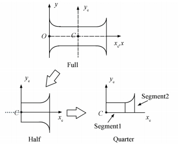 Figure 2 Geometric generation from full to half to quarter in the flexure hinge
 Considering the quarter flexure is formed of i segments that are serially connected, as shown in Fig. 3. By coordinate transformations, when there are only two segments, we can know:
Figure 3
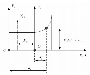 Figure 3 2-Segment in a quarter of the flexure hinges
 $\begin{array}{l}{x_1} = {{x'}_1},{x_2} = {{x'}_2} + {p_1},{y_1}\left( {{x_1}} \right) = {y_1}\left( {{{x'}_1}} \right),{y_2}\left( {{x_2}} \right) = \\\;\;\;\;\;\;\;{y_2}\left( {{{x'}_2}} \right)\end{array}$ (2)
Assuming that we know the compliances defined in Eq.(1) for each of the individual segments in their local reference frames. Using the change of variable given in Eq.(2), the quarter segments defined in the global reference frame xCCyC are determined as
$\left\{ \begin{array}{l}C_{\rm{a}}^{\left( q \right)} = {C_{{\rm{a}}\left( {\rm{C}} \right)}} = C_{\rm{a}}^{\left( 1 \right)} + C_{\rm{a}}^{\left( 2 \right)}\\C_{{\rm{b,t}}}^{\left( q \right)} = {C_{{\rm{b,t}}\left( {\rm{C}} \right)}} = C_{{\rm{b,t}}}^{\left( 1 \right)} + C_{{\rm{b,t}}}^{\left( 2 \right)} + 2{p_1}C_{{\rm{b,c}}}^{\left( 2 \right)} + \\\;\;\;\;\;\;\;\;\;\;p_1^2C_{{\rm{b,r}}}^{\left( 2 \right)}\\C_{{\rm{b,c}}}^{\left( q \right)} = {C_{{\rm{b,c}}\left( {\rm{C}} \right)}} = C_{{\rm{b,c}}}^{\left( 1 \right)} + C_{{\rm{b,c}}}^{\left( 2 \right)} + {p_1}C_{{\rm{b,r}}}^{\left( 2 \right)}\\C_{{\rm{b,r}}}^{\left( q \right)} = {C_{{\rm{b,r}}\left( {\rm{C}} \right)}} = C_{{\rm{b,r}}}^{\left( 1 \right)} + C_{{\rm{b,r}}}^{\left( 2 \right)}\end{array} \right.$ (3)
On the basis of the integral of Eq.(1), conducting two times of symmetry transformation in the Coordinate system xCCyC (mirror symmetry transformation by xC, yC axis successively). According to translating a distance p from the central reference frame x′CCy′C to the end reference frame xOy, as illustrated in Fig. 4, and Eq.(3), we can get the following compliances:
Figure 4
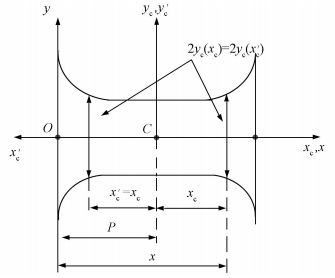 Figure 4 Mirroring and translation of the flexure segment
 $\left\{ \begin{array}{l}{C_{{\rm{a}}\left( {\rm{O}} \right)}} = {{C'}_{{\rm{a}}\left( {\rm{C}} \right)}} = C_{\rm{a}}^{\left( q \right)}\\{C_{{\rm{b,t}}\left( {\rm{O}} \right)}} = {{C'}_{{\rm{b,t}}\left( {\rm{C}} \right)}} + {p^2}{{C'}_{{\rm{b,r}}\left( {\rm{C}} \right)}} = \frac{1}{4}\left( {C_{{\rm{b,t}}}^{\left( q \right)} + {p^2}C_{{\rm{b,r}}}^{\left( q \right)}} \right)\\{C_{{\rm{b,c}}\left( {\rm{O}} \right)}} = p{{C'}_{{\rm{b,r}}\left( {\rm{C}} \right)}} = \frac{p}{4}C_{{\rm{b,r}}}^{\left( q \right)}\\{C_{{\rm{b,r}}\left( {\rm{O}} \right)}} = {{C'}_{{\rm{b,r}}\left( {\rm{C}} \right)}} = \frac{1}{4}C_{{\rm{b,r}}}^{\left( q \right)}\end{array} \right.$ (4)
2.2 Corner-Filleted Flexure HingesIn Fig. 5 we can know the corner-filleted flexure hinge is combined with the simple beam and the right circular flexure hinge. The mainly parameters of the structure are width b, minimum thickness t, fillet radius r and length l; with θ spanning the interval [0, π/2].
Figure 5
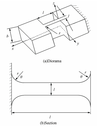 Figure 5 Geometry and parameters
 According to previous literature and materials mechanics' knowledge, it's so difficult to calculate the compliances of the corner-filleted whose front-view sketch is shown in Fig. 6. In order to simply and conveniently get the calculation results, we use means which are described above to divide the flexure hinge into four parts by longitudinal symmetry axis and transverse symmetry axis.
Figure 6
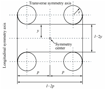 Figure 6 Corner-filleted flexure hinge with axial and transverse symmetry
 The geometric details of the quarter segment are shown in Fig. 7. A quarter segment is structured by a simple beam and a circular portion in the reference frame xCCyC. The following parameter are given: y, r, p. So we can get the length of the simple beam p1=p-r, the length of the circular segment p2=r, as well as ymax=r+y.
Figure 7
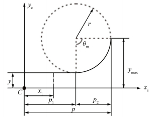 Figure 7 Quarter segment of corner-filleted flexure hinge
 The compliances of segment 1 in Fig. 8(a) are calculated based on Eq.(1) as
Figure 8
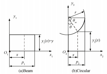 Figure 8 Geometric parameters of two segments of the quarter flexure hinge
 $\begin{array}{l}C_{\rm{a}}^{\left( 1 \right)} = \frac{{{p_1}}}{{Eby}},C_{{\rm{b,t}}}^{\left( 1 \right)} = \frac{{4p_1^3}}{{Eb{y^3}}}\\C_{{\rm{b,c}}}^{\left( 1 \right)} = \frac{{6p_1^2}}{{Eb{y^3}}},C_{{\rm{b,r}}}^{\left( 1 \right)} = \frac{{12{p_1}}}{{Eb{y^3}}}\end{array}$
We can calculate the compliances of segment 2 of Fig. 8(b). which we can consider θm=π/2. Using polar coordinates so that we can know as
$\begin{array}{*{20}{c}}{{y_2}\left( x \right) = {y_2}\left( \theta \right) = y + r\left( {1 - \cos \theta } \right)}\\{x = r\sin \theta ,{\rm{d}}x = r\cos \theta \;{\rm{d}}\theta }\end{array}$
with θ spanning the interval [0, π/2], we can get results as:
$\left\{ \begin{array}{l}C_{\rm{a}}^{\left( 2 \right)} = \frac{r}{{Eb}} \cdot \int_0^{\frac{{\rm{\pi }}}{2}} {\frac{{\cos \theta }}{{{y_2}\left( \theta \right)}}{\rm{d}}\theta } \\C_{{\rm{b,r}}}^{\left( 2 \right)} = \frac{{12r}}{{Eb}} \cdot \int_0^{\frac{{\rm{\pi }}}{2}} {\frac{{\cos \theta }}{{y_2^3\left( \theta \right)}}{\rm{d}}\theta } \\C_{{\rm{b,c}}}^{\left( 2 \right)} = \frac{{12{r^2}}}{{Eb}} \cdot \int_0^{\frac{{\rm{\pi }}}{2}} {\frac{{\cos \theta \cdot \sin \theta }}{{y_2^3\left( \theta \right)}}{\rm{d}}\theta } \\C_{{\rm{b,t}}}^{\left( 2 \right)} = \frac{{12{r^3}}}{{Eb}} \cdot \int_0^{\frac{{\rm{\pi }}}{2}} {\frac{{\cos \theta \cdot {{\sin }^2}\theta }}{{y_2^3\left( \theta \right)}}{\rm{d}}\theta } \end{array} \right.$ (5)
In order to calculate the integration, we change elements to make c=y/r+1, T=θ/2 to get results. Then replacing T to make s=r/y. So we can get the following results:
$\left\{ \begin{array}{l}C_{\rm{a}}^{\left( 2 \right)} = \frac{1}{{Eb}}\left[ {\frac{{2\left( {s + 1} \right)}}{{\sqrt {2s + 1} }}\arctan \sqrt {2s + 1} - \frac{{\rm{\pi }}}{2}} \right]\\C_{{\rm{b,t}}}^{\left( 2 \right)} = \frac{{12}}{{Eb}}\left[ {\frac{{s\left( {2{s^3} + 9{s^2} + 8s + 2} \right)}}{{2\left( {s + 1} \right){{\left( {2s + 1} \right)}^2}}} + \frac{{\left( {s + 1} \right)\left( {2{s^3} - 7{s^2} - 8s - 2} \right)}}{{{{\left( {2s + 1} \right)}^{5/2}}}}\arctan \sqrt {2s + 1} + \frac{{\rm{\pi }}}{2}} \right]\\C_{{\rm{b,c}}}^{\left( 2 \right)} = \frac{6}{{Ebr}}\left[ {\frac{{{s^3}\left( {8{s^2} + 9s + 1} \right)}}{{{{\left( {2s + 1} \right)}^2}}} - \frac{{{s^4}\left( {8{s^2} + 13s + 6} \right)}}{{{{\left( {2s + 1} \right)}^2}\left( {s + 1} \right)}} + \frac{{6{s^3}{{\left( {s + 1} \right)}^2}}}{{{{\left( {2s + 1} \right)}^{5/2}}}}\arctan \sqrt {2s + 1} } \right]\\C_{{\rm{b,r}}}^{\left( 2 \right)} = \frac{6}{{Eb{r^2}}}\left[ {\frac{{{s^3}\left( {3{s^2} + 4s + 1} \right)}}{{\left( {s + 1} \right){{\left( {2s + 1} \right)}^2}}} + \frac{{6{s^4}\left( {s + 1} \right)}}{{{{\left( {2s + 1} \right)}^{5/2}}}}\arctan \sqrt {2s + 1} } \right]\end{array} \right.$ (6)
Now combining Eqs.(5) and (6) into Eq.(3), we can calculate the quarter-flexure compliances. The results are used into Eq.(4) to calculate the compliances of the whole corner-filleted flexure hinges with transfer to the end-point reference frame xOy, as shown in Fig. 4. With the following relationships:
$\begin{array}{*{20}{c}}{y = t/2,s = r/y = 2r/t}\\{p = l/2,{p_1} = p - {p_2} = l/2 - r}\end{array}$
The compliances are simply calculated to become by parameter E, b, l, r, t as
$\left\{ \begin{array}{l}{C_a} = \frac{1}{{Eb}}\left[ {\frac{{l - 2r}}{t} + \frac{{2\left( {2r + t} \right)}}{{\sqrt {t\left( {4r + t} \right)} }}\arctan \sqrt {1 + 4\frac{r}{2}} - \frac{{\rm{\pi }}}{2}} \right]\\{C_{{\rm{b,r}}}} = \frac{{12}}{{Eb{t^3}}}\left[ {\left( {l - 2r} \right) + \frac{{2rt\left( {6{r^2} + 4rt + {t^2}} \right)}}{{\left( {2r + t} \right){{\left( {4r + t} \right)}^2}}} + \frac{{6r\sqrt t \left( {2r + t} \right)}}{{{{\left( {4r + t} \right)}^{5/2}}}}\arctan \sqrt {1 + 4\frac{r}{t}} } \right]\\{C_{{\rm{b,c}}}} = \frac{{6l}}{{Eb{t^3}}}\left[ {l - \frac{{4{r^2}\left( {16{r^2} + 13rt + 3{t^2}} \right)}}{{\left( {2r + t} \right){{\left( {4r + t} \right)}^2}}} + \frac{{12{r^2}\sqrt t }}{{{{\left( {4r + t} \right)}^{5/2}}}}\arctan \sqrt {1 + 4\frac{r}{t}} } \right]\\{C_{{\rm{b,t}}}} = \frac{3}{{Eb{t^3}}}\left[ {\frac{{4\left( {l - 2r} \right)\left( {{l^2} - lr + {r^2}} \right)}}{{3t}} + \frac{{8{l^2}r\left( {6{r^2} + 4rt + {t^2}} \right) + 4l{r^2}\left( {4{r^2} - {t^2}} \right)}}{{\left( {2r + t} \right){{\left( {4r + t} \right)}^2}}} - } \right.\\\;\;\;\;\;\;\;\;\;\frac{{80{r^4} - 24{r^3}t - 8\left( {3 + 2{\rm{\pi }}} \right){r^2}{t^2} - 4\left( {1 + 2{\rm{\pi }}} \right)r{t^3} - {\rm{\pi }}{t^4}}}{{2{{\left( {4r + t} \right)}^2}}} + \\\;\;\;\;\;\;\;\;\;\frac{{48\left( {2r + t} \right){{\left( {l - r} \right)}^2}{r^4}}}{{\sqrt t {{\left( {4r + t} \right)}^{5/2}}}}\arctan \sqrt {1 + 4\frac{r}{t}} + \\\;\;\;\;\;\;\;\;\;\left. {\frac{{2\left( {2r + t} \right)\left( {8{r^4} + 8{r^3}t - 14{r^2}{t^2} - 8r{t^3} - {t^4}} \right)}}{{\sqrt t {{\left( {4r + t} \right)}^{5/2}}}}\arctan \sqrt {1 + 4\frac{r}{t}} } \right]\end{array} \right.$ (7)
2.3 Shear Effects of Short Flexure HingesIf the length-to-width ratio is less than 5, they are short flexure hinges. Now shear effects have to be considered. So the bending compliance Cb, t needs to become as
$C_{{\rm{b,t}}}^s = {C_{{\rm{b,t}}}} + 2\left( {1 + \mu } \right){\alpha _{\rm{s}}}{C_{\rm{a}}}$ (8)
where μ is Poisson's ratio and αs is a shear factor depending on the flexure's cross-section shape; According to the Timoshenko beam theory[18], αs=(12+11μ)/(10+10μ) when sections are the rectangular.
2.4 Finite Element AnalysisThe Hypermesh software has been used to verify the corner-filleted flexure hinge into the finite element model as shown in Fig. 9. All finite element static-load simulations were also run in the software. Two-dimensional(2-D) planar, 6 degree-of-freedom per node, size 0.2-2 mm, PSHELL elements with constant width b=20 mm were created.The material of the flexure hinge is TC4, so we presented a value of E=114 GPa for Young's modulus and μ=0.33 for Poisson's ratio.
Figure 9
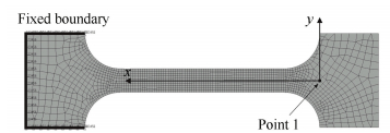 Figure 9 Finite-element model of the corner-filleted flexure hinge
 The fixed constraint was put on one side of the flexure hinge. So the fixed boundary was shown in Fig. 9. Vertical Forces, Horizontal Forces and Moments have been applied at Point 1 in turn in order to read the vertical displacement ux, the horizontal displacement uy and the rotation θz by the respective loading components. So Ca, Cb, ts, Cb, c, Cb, r can be calculated by Eqs (1) and (8).
Table 1 summarizes the analytical and finite element results together with the design parameters of several flexure hinges. Analytical results can be computed by Eq. (7). So we can get that the results were in good agreement. The maximum errors between analytical results and finite element data were less than 8%.
表 1
Analytic FEM Analytic FEM Analytic FEM Analytic FEM
20 2.0 3 109.49 109.18 119.430 113.36 155.640 143.27 398.52 430.70
20 2.0 4 99.468 98.96 112.450 107.02 141.120 132.45 376.87 405.87
20 2.5 3 56.899 56.61 61.973 57.99 82.034 76.31 322.51 356.79
20 2.5 4 51.975 51.52 58.747 56.13 75.008 69.93 306.66 353.60
30 2.0 3 175.280 174.97 277.830 264.91 549.120 516.73 617.81 659.97
30 2.0 4 165.260 164.88 267.360 251.77 516.710 477.76 596.17 646.30
30 2.5 3 90.583 89.73 143.490 135.86 286.560 268.89 497.95 436.25
30 2.5 4 85.660 85.06 138.650 129.72 271.120 259.71 482.10 529.99
Table 1 Analytic result and finite element data
3 The Micro-Rotation Compliant MechanismWe referred to compliant support[19], rotational flexure joint[20] and distributed flexure hinge[21]designed a micro-rotation compliant mechanism for one-dimensional rotation. It has 8 corner-filleted flexure hinges array arrangement around the centre O. The reference structure is shown in Fig. 10.
Figure 10
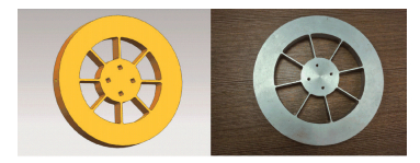 Figure 10 Simulate model and Sample of the compliant mechanism
 The geometric structures of 8 corner-filleted flexure hinges are absolutely same and their distributions are completely symmetry. If we assume that the material used in mechanism has no material non-linearity during deformation under stress, then when the center of mechanism bears moment act, micro-rotation compliant mechanism does not rotate central drift and the whole structure keeps stable loading, which is very suitable for spatial device with high demand for positional accuracy.
3.1 Analytical Model of the Compliant MechanismIn this compliant mechanism, each corner-filleted flexure unit is completely geometric distribution. Therefore, we should calculate the force deformation of single flexure unit of primary motion and neglect force deformation of outer circular ring and inner cylinder. And then we obtain the force deformation of the whole compliant mechanism through force analysis.
As shown in Fig. 11, because of completely symmetry in structure, axial force Fx suffered by single flexure unit can offset each other, which is need not to calculate such force. The torque M received by center can be decomposed into longitudinal force Fy and moment Mz loaded by freedom end of individual flexure unit. Besides, axial centre line of freedom end always points to compliant mechanism center O after force; so angle displacement θ of freedom end can be gotten according to boundary condition; and the deflection of displacement is d=2Rsin(θ/2). R is the inner cylinder's radius.
Figure 11
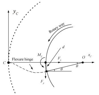 Figure 11 The single flexure hinge with loads and deformations/displacements in the compliant mechanisms
 According to mechanics knowledge with considering shearing force, we can get:
$\left\{ \begin{array}{l}{C_{{\rm{b,r}}}}{M_z} + {C_{{\rm{b,c}}}}\left( { - {F_y}} \right) = \theta \\{C_{{\rm{b,c}}}}{M_z} + C_{{\rm{b,t}}}^s\left( { - {F_y}} \right) = - d\end{array} \right.$
After calculating:
$\left\{ \begin{array}{l}{M_z} = \frac{{R{C_{{\rm{b,c}}}} + C_{{\rm{b,t}}}^s}}{{{C_{{\rm{b,r}}}}C_{{\rm{b,t}}}^s - C_{{\rm{b,c}}}^2}}\theta \\{F_y} = \frac{{R{C_{{\rm{b,r}}}} + {C_{{\rm{b,c}}}}}}{{{C_{{\rm{b,r}}}}C_{{\rm{b,t}}}^s - C_{{\rm{b,c}}}^2}}\theta \end{array} \right.$ (9)
So the whole moment of the compliant mechanism is
$M = N \times \left( {R{F_y} + {M_z}} \right)$ (10)
where N means number of flexure units, here is 8. So putting it into Eqs. (9) and (10):
$M = \frac{{8\theta \left( {{R^2}{C_{{\rm{b,r}}}} + 2R{C_{{\rm{b,c}}}} + C_{{\rm{b,t}}}^s} \right)}}{{{C_{{\rm{b,r}}}}C_{{\rm{b,t}}}^s - C_{{\rm{b,c}}}^2}}$ (11)
We can define that:
$K = M/\theta $ (12)
which is usually called rigidity of the compliant mechanism can only be determined by geometric parameters.
3.2 Rigidity's Variability of Geometric ParametersNow we study how the rigidity changes by variable geometric parameters. At the time, every compliant mechanism was researched in terms of one of the above parameters while keeping the other parameters constant. For all the simulations, the values E=71 GPa, μ=0.33 and b=16 mm were invariable.
In Fig. 12(a), for instance, it shows that the variation of the rigidity by the fillet radius for l=35 mm, t=2 mm, and R=30 mm. So we can see the nonlinear character of the moment. When r≤0.464 mm, the rigidity becomes smaller by the larger value of the fillet radius. When r≥0.464 mm, the rigidity becomes larger by the larger value of the fillet radius. But for actual manufacturer, the size should not be too small, we always make r≥0.5 mm. So the rigidity varies smaller with fillet radius varying smaller now.
Figure 12
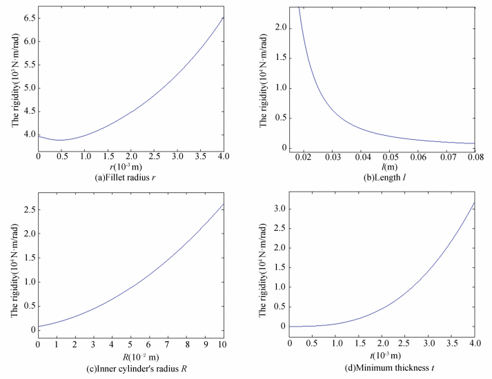 Figure 12 The rigidity as a function of geometric parameters
 The same variation of the rigidity has been plotted to analyze the effects of changing the parameters l (in Fig. 12(b)), R (in Fig. 12(c)), t (in Fig. 12(d)) with r=2 mm. By the larger values of t, R as well as smaller values of l, it can be seen that the rigidity nonlinearly becomes larger.
3.3 Finite Analysis and Experimental TestGeometric model of the micro-rotation compliant mechanism is established through UG software with l=35 mm, t=2 mm, r=2 mm, b=16 mm and R=30 mm. The material of the mechanism is LC9 with the values E=71 GPa, μ=0.33. Then finite element model is founded after importing into Hypermesh software, and grids adopt 2nd-order tetras by size 2 mm, as shown in Fig. 13. In order to improve the accuracy, grids of flexure hinges is more intensive; We put fixed constraints on the outer circular ring to make the outer part of the compliant mechanism fixed; and we put moment constraints on the central point to make the flexure hinge in the compliant mechanism deformed. According to different moment constraints, recording the displacements on the Point 1 which is in the maximum radius of the mechanism. The rotary angle θ1 is shown as follows:
Figure 13
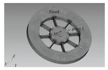 Figure 13 Finite-element model of the compliant mechanism
 ${\theta _1} = {d_1}/{{R'}_{\max }}$
where d1 is the displacement on the Point 1 which is displayed by the software; R'max is defined as the maximum radius of the inner cylinder.
After data reduction, we put them into Table 2.
表 2
FEA Experiment
3.92 0.847 0.826
2.94 0.635 0.616
1.96 0.423 0.402
0.98 0.212 0.196
Table 2 FEA and experiment data
Now the verification of the rigidity of compliant mechanism is carried out by experiments. Because the main part of the deformation is the flexible hinge which can be simplified as a cantilever beam with one side fixed and the load on other side, when the fixed end and the deformed end are exchanged, because the stress and deformation have the interaction, the results are consistent with the deformation of the angular rotation. So we can exert load on the outer circular ring and make the inner cylinder fixed in the test. Then exerting a pair of parallel but reversed tangential force on the maximum radius of the outer circular ring in order to form equivalent moment in the center, the tangential force can be provided by the gravity of loads. A small solid is fixed on the outer circular ring for inductive micrometer measuring the micro displacement conveniently. The measuring point nearly is on the maximum radius of the compliant mechanism, as shown in Fig. 14. The micro rotary angle θ and the equivalent moment can be calculated as follows:
Figure 14
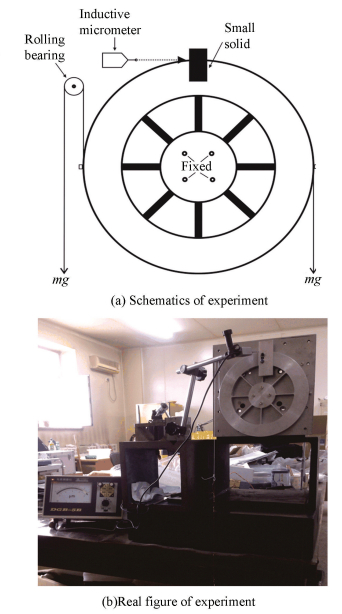 Figure 14 Experiment of the compliant mechanism
 $\theta = d/{R_{\max }},M = mg{R_{\max }}$
where d is the displacement on the measuring point which is displayed by the inductive micrometer; Rmax is defined as the maximum radius of the outer circular ring; m is defined as the whole mass of loads.
We also put reorganized data into Table 2.
Reorganized data in Table 2 for linear fitting within original point, we can get fitting lines of Angle-Moment of the compliant mechanism as shown in Fig. 15. The linearity of fitting curve is very good, so the rigidity of the compliant mechanism can be calculated by Eq. (12) which is the slope of the fitting curve. The finite fitting result is 4 629.2 N·m/rad while the experimental fitting result is 4 728.5 N·m/rad. The analysis result we can get by Eq.(11) is 4 484.5 N·m/rad.
Figure 15
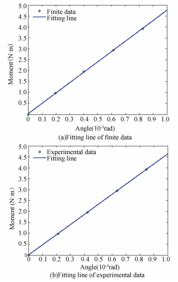 Figure 15 Fitting lines of Angle-Moment
 It follows from this that respectively comparing finite result and experimental result with analysis result, relative errors are: 3.23% and 5.44%. However, finite element simulation and theoretical analysis have some errors mainly because of the finite element calculation method. If the grid and constraints are applied more precisely, the error will be smaller. And there are many reasons for the error betweenexperimental results and theoretical analysis, mainly including manufacturing error, measurement error and environmental error. Manufacturing error can be reduced by precision machining; the measurement error is mainly related to the measuring instrument. At present the resolution of inductive micrometer is 0.01 μm which is already very high so that we can accept measurement results. If there are conditions later, the collimator with 0.2″ resolution can be used to reduce the error; environment error is more complex, only to ensure that the experiment without other interference. In addition, the gravity of the compliant mechanism will cause some errors. But the gravity error is proved about 0.2%, and in the future the complaint mechanism may be applied in space. Therefore the experimental results will be more close to the theoretical analysis.
But overall, now all of errors are less than 5.5% which is already very small. So after finite simulation and experimental test, we can tell that analytical model of the micro-rotation compliant mechanism is accurate and reliable.
4 Application Based on OptimizationNow we need to design a micro adjustment device to compensate the image spin for a large space camera in the space station which only asked for one-dimensional rotation. The temporary technical requirements of the micro adjustment device that will be changed by design process of other parts are relatively high as working range 17", working response frequency 25 Hz and so on, at the same time the working moment should be as small as possible. The spatial location is shown in Fig. 16. The compliant mechanism's bottom is optical encoders which control the device by the load (the space camera) position. The power element is a pair of piezoelectric ceramics drive.
Figure 16
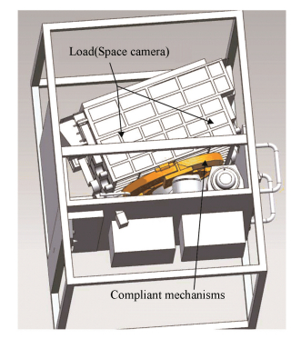 Figure 16 The spatial location of the compliant mechanism
 According to these requirements, for this compliant mechanism, under certain maximum angle displacement (θ≤17″), the moment needed in the center should be minimum and the fundamental frequency after carrying the load could not be lower than some values (f≥25×2 Hz). Because there are some errors between theoretical design and actual application, we select the fundamental frequency as f≥50×1.1=55 Hz in design. At the same time, the material of this mechanism is Tc10 and fatigue stress of this material is 320 MPa. So the maximum permissible stress of compliant mechanism should not be more than σmax≤320/2=160 MPa when safety coefficient is 2. In this problem because θ is constant, the minimum moment means the minimum rigidity under above conditions can only be determined by geometric parameters. In order to get the minimum value of the moment for easily choosing drive components, the following calculations we all use Eq. (11) instead of Eq. (12).
So on basis of spatial size and estimated moment, we preliminarily choose r=4 mm, t=3 mm, l=40 mm and R=160 mm in design. The value of E=114 GPa, μ=0.33, b=60 mm and θ=17″=17π/(3 600×180) rad were constant. By Eqs. (7), (8) and (11), we can calculate that M=82.58 N·m. But this result can not be ensured to be minimum value, and whether it is satisfied the constraints, there need some optimizations.
4.1 Mathematical ModelIn order to make the moment smaller, we need to optimize the size of the compliant mechanism with frequency and stress meeting the demands. Therefore, mathematical model of the optimization in this micro-rotation compliant mechanism is shown as follows:
${f_{{\rm{obj}}}} = \min \left( {M\left( {r,l,R,t} \right)} \right) = \min \left( {M\left( x \right)} \right)$
Let
${x_1} = r,{x_2} = t,{x_3} = l,{x_4} = R,\mathit{\boldsymbol{x = }}{\left( {{x_1},{x_2},{x_3},{x_4}} \right)^{\rm{T}}}$ (13)
$\left\{ \begin{array}{l}{\rm{nonlinear}}\;{\rm{restriction}}:c\left( \mathit{\boldsymbol{x}} \right) \le 0;ceq\left( \mathit{\boldsymbol{x}} \right) = 0\\{\rm{linear}}\;{\rm{inequality}}\;{\rm{restriction}}:\mathit{\boldsymbol{A}} \cdot \mathit{\boldsymbol{x}} \le \mathit{\boldsymbol{b}}\\{\rm{boundary}}\;{\rm{restriction}}:\mathit{\boldsymbol{lb}} < \mathit{\boldsymbol{x}} < \mathit{\boldsymbol{ub}}\end{array} \right.$
where M(r, l, R, t)=M(x) can be defined in Eqs.(7), (8) and (11).
Now we need to pull analysis model of the fundamental frequency and the maximum stress. If it is assumed that the whole moment of inertia of the compliant mechanism with load is J (which will be chosen as 7.5 kg·m2 in this project), so the fundamental frequency is:
$f = \frac{1}{{2{\rm{\pi }}}}\sqrt {\frac{K}{J}} = \frac{1}{{2{\rm{\pi }}}}\sqrt {\frac{M}{{J\theta }}} $ (14)
As a result, the maximum stress on the compliance can be defined as:
${\sigma _{\max }} = 6{k_b}\frac{{{M_z} + \left( { - {F_y}} \right)l}}{{b{t^2}}} + {k_t}\frac{{{F_x}}}{{bt}}$ (15)
where Mz, Fy can be found in Eq.(9). The stress concentration factors kb and kt which can be found in Ref. [22] are defined as:
$\left\{ \begin{array}{l}{k_{\rm{b}}} = - 0.1729{\left( {\frac{r}{t}} \right)^3} + 0.8539{\left( {\frac{r}{t}} \right)^2} - \\\;\;\;\;\;\;\;\;1.4265\left( {\frac{r}{t}} \right) + 1.9613\\{k_t} = 0.1721{\left( {\frac{r}{t}} \right)^4} - 0.9288{\left( {\frac{r}{t}} \right)^3} + \\\;\;\;\;\;\;\;\;1.8387{\left( {\frac{r}{t}} \right)^2} - 1.6593\left( {\frac{r}{t}} \right) + 1.669\end{array} \right.$
The axial force can be defined as:
${F_x} = Cx = \frac{x}{{{C_{\rm{a}}}}}$
For micro angular rotation, approximatively considering:
$\begin{array}{l}x \approx \sqrt {{{\left( {l + R - R\cos \theta } \right)}^2} + {{\left( {R\sin \theta } \right)}^2}} - l \approx \\\;\;\;\;\;\;\;\sqrt {{l^2} + {{\left( {R\theta } \right)}^2}} - l\end{array}$
Because of restriction of spatial sizes: l+R≤220 mm, R≥130 mm, 10≤l≤80 mm. For convenient and accurate manufacture, some sizes should not be too small with r≥3 mm, t≥3 mm, l≥2r; so linear inequality restriction matrix and boundary restriction are shown as follows:
$\begin{array}{*{20}{c}}{\mathit{\boldsymbol{A = }}\left[ {\begin{array}{*{20}{c}}0&0&1&1\\2&0&{ - 1}&0\end{array}} \right]}\\{\mathit{\boldsymbol{b = }}\left[ {\begin{array}{*{20}{c}}{0.22}\\0\end{array}} \right]}\\{\mathit{\boldsymbol{lb = }}{{\left[ {\begin{array}{*{20}{c}}{0.003}&{0.003}&{0.01}&{0.13}\end{array}} \right]}^{\rm{T}}}}\\{\mathit{\boldsymbol{ub = }}{{\left[ {\begin{array}{*{20}{c}}{0.1}&{0.1}&{0.08}&{0.2}\end{array}} \right]}^{\rm{T}}}}\end{array}$
There are two kinds of following inequality restrictions in the nonlinear restriction, and this optimized problem does not have nonlinear equality restriction:
1) Inequality restriction of the compliant mechanism's frequency, on the basis of Eq.(14):
${c_1}\left( x \right) = - M + J\theta \times {\left( {110{\rm{\pi }}} \right)^2} \le 0$
2) Inequality restriction of the compliant mechanism's permissible stress, on the basis of Eq.(21):
$\begin{array}{l}{c_2}\left( x \right) = 6{k_{\rm{b}}}\frac{{{M_z} + \left( { - {F_y}} \right)l}}{{b{t^2}}} + {k_t}\frac{{\sqrt {{l^2} + {{\left( {R\theta } \right)}^2}} - l}}{{{C_{\rm{a}}}bt}} - \\\;\;\;\;\;\;\;\;\;\;\;\;160 \le 0\end{array}$
The optimization can be regarded as a process of seeking minimum value of function. This optimal model is to calculate minimum value of constraint and nonlinear function with single goal and multiple variables. Based on features of each optimal instruction, we choose "fmincon" local optimal instruction in the end and optimize the function through Matlab software. Assessment criteria of "fmincon" optimal result contains: variation trend of targeting functional value, Tolerance of Constraints and First-Order Optimality.
For the optimization, First-Order Optimality can be calculated as shown in:
$\begin{array}{l}\min f\left( x \right),{r_i}\left( x \right) \le 0,\left( {1 \le i \le m} \right),{g_j}\left( x \right) \le 0,\\\;\;\;\;\;\;\;\;\;\;\;\;\;\;\;\left( {1 \le j \le k} \right)\end{array}$ (16)
The corresponding Lagrange function was
$L\left( {x,\lambda } \right) = f\left( x \right) + \sum {{\lambda _{r,i}}{r_i}\left( x \right)} + \sum {{\lambda _{g,j}}{g_j}\left( x \right)} $
The Kuhn-Tucker condition was
$\left\{ \begin{array}{l}{\nabla _x}L\left( {x,\lambda } \right) = 0\\{\lambda _{r,i}}{r_i}\left( x \right) = 0\\\left\| {{\nabla _x}L\left( {x,\lambda } \right)} \right\| = \left\| {\nabla f\left( x \right)\sum {{\lambda _{r,i}}\nabla {r_i}\left( x \right)} + } \right.\\\;\;\;\;\;\;{\left. {\sum {{\lambda _{g,j}}\nabla {g_j}\left( x \right)} } \right\|_\infty }\end{array} \right.$ (17)
Infinite series of the vector
First-Order Optimality represents distance from variables to optimal value of variable (the variable when the objective function sets a minimum) during iterative procedure. The smaller of the value, the closer of iterative value gets to optimal value. It is a necessary, but not sufficient condition for objective function with constraints to gain minimum value.
4.2 Optimize ProcessFor this compliant mechanism, we adopt "fmincon" local searching optimization to get local best variable value, on the basis of Eqs. (13), (16) and (17), at the time objective function becomes smaller by more iteration, while satisfy optimized condition, final objective function's local best variable value is 74.986 N·m. During more iteration, Tolerance of Constraints and First-Order Optimality are continuously closed to 0. After 4 iteration, Tolerance of Constraints is 1e-6, First-Order Optimality is 1.39e-5, which is very closed to 0. Indicating local optimized results are very reliable, best variable value is
$\mathit{\boldsymbol{x = }}\left[ {\begin{array}{*{20}{c}}{0.003}&{0.003}&{0.03473}&{0.13}\end{array}} \right]$
In order to convenient design and manufacture, on the basis of relationship between geometric parameters and the moment, final sizes are r=3 mm, t=3 mm, l=34.5 mm and R=130 mm. Putting them into Eqs. (11), (14) and Eq.(15), we can calculate that M=76.49 N·m. Where f=55.55 Hz, σmax=12.338 MPa, all meet constraint conditions.
Now we get an appropriate geometrical size of the micro-rotation compliant mechanism without 3D modeling and FEA. This method is more simple and convenient, and the results can also satisfy the requirement.
5 ConclusionsThe flexibility formula of corner-filleted flexure hinges is deduced applying the method of symmetry transformations and coordinates translation in an easier and more convenient way compared with applying traditional method of direct calculation with calculus. It is proved that the results of theoretical derivation and those of finite element are generally consistent, with an error not exceeding 8%. With the flexibility formula of chamfer flexure hinges, a one-dimensional rotating mechanism, namely the micro-rotation compliant mechanism is developed and the theoretical formula of the working moment/rigidity is deduced. It also analyzes the influence of structural parameters on working rigidity and confirms the accuracy and reliability of the theoretical formula by finite element analysis and experimental verification. Finally, a micro-rotation compliant mechanism is designed corresponding to the requirements of a space project and optimizes its size via fmincon instructions of Matlab software to make the viable working moment as small as possible. The above results illustrate that designing and optimizing the structures by this analysis model is not only convenient but also reliable so that complicated 3D modeling and finite element analysis are not needed, which carries great theoretical and engineering significance.
References
[1] Smith S T, Chetwynd D G, Bowen D K. Design and assessment of monolithic high precision translation mechanisms. Journal of Physics E: Scientific Instruments, 1987, 20(8): 977-983. DOI:10.1088/0022-3735/20/8/005 (
 0)
0)[2] Yong Y K, Lu T-F. Kinetostatic modeling of 3-RRR compliant micro-motion stages with flexure hinges. Mechanism and Machine Theory, 2009, 44(6): 1156-1175. DOI:10.1016/j.mechmachtheory.2008.09.005 (
 0)
0)[3] Kim H-S, Kim E-J, Song B-S. Diamond turning of large off-axis aspheric mirrors using a fast tool servo with on-machine measurement. Journal of Materials Processing Technology, 2004, 146(3): 349-355. DOI:10.1016/j.jmatprotec.2003.11.028 (
 0)
0)[4] Paros J, Weisbord L. How to design flexure hinges. Machine Design, 1965, 37: 151-156. (
 0)
0)[5] Wu Yingfei, Zhou Zhaoying. Design calculations for flexure hinges. Review of Scientific Instrument, 2002, 73: 3101-3106. DOI:10.1063/1.1494855 (
 0)
0)[6] Tian Y, Shirinzadeh B, Zhang D. Closed-form compliance equations of filleted V-shaped flexure hinges for compliant mechanism design. Precision Engineering, 2010, 34(3): 408-418. DOI:10.1016/j.precisioneng.2009.10.002 (
 0)
0)[7] Lobontiu N, Paine J S N, García E, et al. Design of symmetric conic-section flexure hinges based on closed-form compliance equations. Mechanism and Machine Theory, 2002, 37(5): 477-498. DOI:10.1016/S0094-114X(02)00002-2 (
 0)
0)[8] Lobontiu N, Cullin M, Petersen T, et al. Planar com-pliances of symmetric notch flexure hinges: the right circularly corner-filleted parabolic design. IEEE Transactions on Automation Science and Engineering, 2014, 11(1): 169-176. DOI:10.1109/TASE.2012.2228853 (
 0)
0)[9] Lin Rongzhou, Zhang Xianmin, Long Xuejun, et al. Hybrid flexure hinges. Review of Scientific Instruments, 2013, 84: 085004. DOI:10.1063/1.4818522 (
 0)
0)[10] Xu W, King T. Flexure hinges for piezoactuator displacement amplifiers: flexibility, accuracy, and stress considerations. Precision Engineering, 1996, 19(1): 4-10. DOI:10.1016/0141-6359(95)00056-9 (
 0)
0)[11] Lobontiu N, Paine J S N, Garcia E, et al. corner-filleted flexure hinges. Journal of Mechanical Design, 2001, 123(3): 346-352. DOI:10.1115/1.1372190 (
 0)
0)[12] Lobontiu N, Garcia E. Two-axis flexure hinges with axially-collocated and symmetric notches. Computers & Structures, 2003, 81(13): 1329-1341. DOI:10.1016/S0045-7949(03)00056-7 (
 0)
0)[13] Chen Guimin, Jia Jianyuan, Li Zhiwu. Right-circular corner-filleted flexure hinges. Proceedings of the 2005 IEEE International Conference on Automation Science and Engineering. Piscataway: IEEE, 2005. 249-253. DOI: 10.1109/COASE.2005.1506777. (
 0)
0)[14] Meng Qiaoling, Xu Jia, Li Yangmin. Optimal design of proportion compliant mechanisms with corner-filleted flexure hinges. Proceedings of the 13th IEEE International Conference on Nanotechnology. Piscataway: IEEE, 2013. 460-465. DOI: 10.1109/NANO.2013.6720882. (
 0)
0)[15] Qin Yanding, Shirinzadeh Bijan, Zhang Dawei, et al. Compliance modeling and analysis of statically indeterminate symmetric flexure structures. Precision Engineering, 2013, 37(2): 415-424. DOI:10.1016/j.precisioneng.2012.11.004 (
 0)
0)[16] Lobontiu N, Cullin M. In-plane elastic response of two-segment circular-axis symmetric notch flexure hinges: The right circular design. Precision Engineering, 2013, 37(3): 542-555. DOI:10.1016/j.precisioneng.2012.12.007 (
 0)
0)[17] Noveanu S, Lobontiu N, Lazaro J, et al. Substructure compliance matrix model of planar branched flexure-hinge mechanisms: Design, testing and characterization of a gripper. Mechanism and Machine Theory, 2015, 91: 1-20. DOI:10.1016/j.mechmachtheory.2015.04.001 (
 0)
0)[18] Cowper G R. The shear coefficient in timoshenko's beam theory. Journal of Applied Mechanics, 1966, 33(2): 335-340. DOI:10.1115/1.3625046 (
 0)
0)[19] DeVries J, Neill D, Hileman E. LSST telescope primary/tertiary mirror hardpoints. Proceedings of the SPIE 7739, Modern Technologies in Space-and Ground-based Telescopes and Instrumentation. Bellingham: SPIE, 2010, 7739: 77391J-1-77391J-12. DOI: 10.1117/12.857473. (
 0)
0)[20] Kim K, Gweon D, Choi N, et al. Design and modeling of XYθ H type stage using 1 rotational DOF flexure joint. Proceedings of the SPIE 8205, 2011 International Conference on Photonics, 3D-Imaging, and Visualization. Bellingham: SPIE, 2011. 820518-1-820518-6. DOI: 10.1117/12.906153. (
 0)
0)[21] Yu Jingjun, Xu P, Sun Minglei, et al. A new large-stroke compliant joint & micro/nano positioner design based on compliant building blocks. Proceedings of the ASME/IFToMM International Conference on Reconfigurable Mechanisms and Robots. 2009. Piscataway: IEEE, 2009. 409-416. (
 0)
0)[22] Chen Guimin, Wang Jialu, Liu Xiaoyuan. Generalized equations for estimating stress concentration factors of various notch flexure hinges. Journal of Mechanical Design, 2014, 136(3): 031009. DOI:10.1115/1.4026265 (
 0)
0)