Dianbo Ren, Guanzhe Zhang,Hangzhe Wu
(School of Automotive Engineering, Harbin Institute of Technology(Weihai), Weihai 264209, China)
Abstract:
In this paper, it studies the problem of trajectory planning and tracking for lane changing behavior of vehicle in automatic highway systems. Based on the model of yaw angle acceleration with positive and negative trapezoid constraint, by analyzing the variation laws of yaw motion of vehicle during a lane changing maneuver, the reference model of desired yaw angle and yaw rate for lane changing is generated. According to the yaw angle model, the vertical and horizontal coordinates of trajectory for vehicle lane change are calculated. Assuming that the road curvature is a constant, the difference and associations between two scenarios are analyzed, the lane changing maneuvers occurred on curve road and straight road, respectively. On this basis, it deduces the calculation method of desired yaw angle for lane changing on circular road. Simulation result shows that, it is different from traditional lateral acceleration planning method with the trapezoid constraint, by applying the trapezoidal yaw acceleration reference model proposed in this paper, the resulting expected yaw angular acceleration is continuous, and the step tracking for steering angle is not needed to implement. Due to the desired yaw model is direct designed based on the variation laws of raw movement of vehicle during a lane changing maneuver, rather than indirectly calculated from the trajectory model for lane changing, the calculation steps are simplified.
Key words: intelligent transportation systems lane changing yaw angle model trajectory planning
DOI:10.11916/j.issn.1005-9113.2016.01.004
Clc Number:U461.2
Fund:
Ren Dianbo, Zhang Guanzhe, Wu Hangzhe.Symbol Reference Model of Desired Yaw Angle for Automated Lane Changing Behavior of Vehicle[J]. Journal of Harbin Institute of Technology, 2016, 23(1): 23-33. DOI: 10.11916/j.issn.1005-9113.2016.01.004.

Fund Sponsored by the Natural Science Foundation of Shandong Province(Grant No.ZR2010FM008, ZR2015FM024) and the Natural Scientific Research Innovation Foundation in Harbin Institute of Technology(Grant No. HIT.NSRIF. 2011117). Corresponding author E-mail: r_dianbo@163.com. Article history Received: Dec 11, 2014
Contents Abstract Full text Figures/Tables PDF
Symbol Reference Model of Desired Yaw Angle for Automated Lane Changing Behavior of Vehicle
Ren Dianbo

 , Zhang Guanzhe, Wu Hangzhe
 School of Automotive Engineering, Harbin Institute of Technology(Weihai), Weihai 264209, China
Received: Dec 11, 2014
fund: Sponsored by the Natural Science Foundation of Shandong Province(Grant No.ZR2010FM008, ZR2015FM024) and the Natural Scientific Research Innovation Foundation in Harbin Institute of Technology(Grant No. HIT.NSRIF. 2011117).
Corresponding author: E-mail: r_dianbo@163.com.
Abstract: In this paper, it studies the problem of trajectory planning and tracking for lane changing behavior of vehicle in automatic highway systems. Based on the model of yaw angle acceleration with positive and negative trapezoid constraint, by analyzing the variation laws of yaw motion of vehicle during a lane changing maneuver, the reference model of desired yaw angle and yaw rate for lane changing is generated. According to the yaw angle model, the vertical and horizontal coordinates of trajectory for vehicle lane change are calculated. Assuming that the road curvature is a constant, the difference and associations between two scenarios are analyzed, the lane changing maneuvers occurred on curve road and straight road, respectively. On this basis, it deduces the calculation method of desired yaw angle for lane changing on circular road. Simulation result shows that, it is different from traditional lateral acceleration planning method with the trapezoid constraint, by applying the trapezoidal yaw acceleration reference model proposed in this paper, the resulting expected yaw angular acceleration is continuous, and the step tracking for steering angle is not needed to implement. Due to the desired yaw model is direct designed based on the variation laws of raw movement of vehicle during a lane changing maneuver, rather than indirectly calculated from the trajectory model for lane changing, the calculation steps are simplified.
Key words: intelligent transportation systems lane changing yaw angle model trajectory planning
1 IntroductionIntelligent transportation system is a new concept developed in recent years. It has been an effective way to solve the traffic problem by establishing a real-time, accurate, and efficient transportation management system based on the integrated application of some advanced technologies, such as information, communication, and control technology, etc[1]. Automated highway system is an important part of intelligent transportation system, aiming to realize autonomous driving of intelligent vehicles on intelligent roadways by the hybrid safety architecture that combines vehicle-to-vehicle communication and vehicle-to-roadside sensor communication[2]. The key of driverless technology is the research, design and development of automatic control system of vehicle. Generally, according to the control targets, the vehicle automatic control can be divided into two aspects to study, longitudinal control and lateral control, respectively. Lane changes are important in traffic flow operations[3-4]. The automatic control for lane changing is belonging to the lateral control of vehicle, aiming to make vehicle from one lane into another along the expected trajectory[5-6]. In a general way, the control strategy for lane changing behavior of vehicle can be divided into two parts to study, trajectory planning and trajectory tracking. According to different types of trajectory in Ref.[7], the mode of lane changing can be divided into two cases, the navigation of lane changing by magnetic nail and free way of lane changing. Using the mode of magnetic nail navigation, lane changing trajectory is the actual path of magnetic nails’ laying track. However, in the mode of free lane changing, the trajectory is a virtual path planned between two lanes of road based on the real-time lane changing demand[8]. Because the vehicle is tracking a virtual lane changing path when the mode of free lane changing is adopted, it’s more flexible than the mode of magnetic nail navigation in which the actual path of lane changing is adopted. Hence, the study for automatic lane changing of vehicle generally uses the mode of free lane changing, in which the planned lane changing trajectory is virtual.
There are many types of virtual trajectory planning method for lane changing, such as assuming the vehicle location trajectory is contented with circular arc or sine function constraints, or the expected lateral acceleration is designed as positive and negative trapezoid [9]. Another lane changing trajectory planning method is based on odd polynomial or Beisaier curve, and so on[10-12]. Since the actual lane changing process and the vehicle following behavior influence each other,Yang[13] designed a lane changing model in consideration of the implementation process, with the simulation of traffic flow under different numbers of lanes of road. Xu[14] put forward an extended dynamic model to represent evasive lane-change behavior. Zhao[15] modified lane changing rules and set up cellular automata model in a multiple lanes road scene when emergency vehicles exist.
Tracking of lane changing trajectory is related to lane changing trajectory types. For magnetic nail navigation mode, on-board magnetic sensors can be used, by testing the information of magnetic nail embedded along the lane changing trajectory, the deviation between the mass center of vehicle and the position of desired trajectory was calculated, accordingly, the controller can be designed by using the feedback of the position deviation, as in Ref.[16]. However, by using the mode of free lane changing, in a lane changing process, the centroid position of vehicle is difficult to detect for it is moving along a virtual path, so the onboard sensors should be used to detect yaw angle and yaw rate information of vehicle. On this basis, the deviation of yaw angle and yaw rate from the reference values should be calculated to serve as the feedback. By tracking the desired yaw angle and yaw rate, trajectory tracking for lane changing can be achieved indirectly, as in Ref.[17]. However, if a lane changing behavior is realized by yaw angle tracking, the expected yaw angle, yaw rate and yaw angular acceleration information should be calculated according to the mathematical model of lane changing trajectory.
From the above analysis, we can see that when use free lane changing mode to achieve a lane changing behavior through the yaw angle tracking, the planning of trajectory model for lane changing is not required, but we need to design anticipated yaw angle model according to lane changing constraints. Actually, lane changing trajectory model and yaw angle model are interrelated. Trajectory model describes the longitudinal and lateral states of vehicle in the lane changing process, and the yaw angle model reflects the vehicle yaw motion in lane changing process. According to lane changing trajectory model, expected yaw angle for lane changing can be calculated. In turn, lane changing trajectory coordinates can be also calculated if the yaw angle model is known. Hence the reference model for lane changing should not only refer to lane changing trajectory model, but also include the yaw angle model. However, up to now, the research about lane changing reference model mainly focuses on the trajectory planning problem, and the desired yaw angle is calculated indirectly by the trajectory model for changing lanes.
From analyzing the yaw motion law of vehicle in lane changing scene, assuming that the lane changing behavior occurs in two scenarios, straight and circular road section, respectively, in this paper, the trapezoidal yaw angular acceleration model for lane changing is proposed, on this basis, the reference model of desired yaw angle and yaw rate are deduced, by lateral dynamical model of vehicle, the yaw angle tracking control law is designed. Due to the fact that the desired yaw model is not calculated from the trajectory model for lane changing, the calculation steps are simplified, thus to facilitate its application in practice.
2 Lane Change Reference Model on Straight Road2.1 Linear Yaw Angle ModelAssuming that a changes lane behavior of vehicle happened on a straight road, the lane changing trajectory can be shown in Fig. 1.
Figure 1
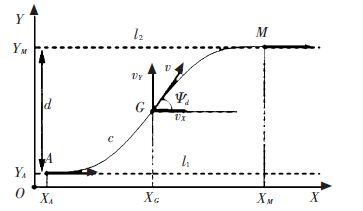 Figure 1 Schematic of lane changing trajectory
 In Fig. 1,l1 and l2 denote the center lines of start lane and target lane for a lane changing behavior, respectively, and d is the spacing distance between l1 and l2. In the global coordinate system shown in Fig. 1,X-axis (horizontal axis) is parallel to the lane centerline, along with traveling direction of vehicle at the start time of a lane changing maneuver; Y-axis(vertical axis) is perpendicular to centerline of lane, along the direction from the start lane to the target lane. c represents the trajectory curve for lane changing, on which,A,M and G are points corresponding to the start, the end and the middle position of vehicle in lane changing process, respectively. The lane changing behavior is namely the traveling of the vehicle centroid starting from point A to point M along the trajectory curve c. v represents the vehicle speed, and ψd represents the vehicle desired yaw angle. In the global coordinate system, speed v is decomposed into horizontal and vertical movements, namely vX and vY, and vX=vcos ψd, vY=vsin ψd. When changing lanes, the vehicle longitudinal axis should track tangential direction of lane changing trajectory, that is v always changes its orientation along the tangential direction of curve c, so ψd is also the angle between the tangential direction of lane changing trajectory and the longitudinal axis. According to the known lane changing trajectory, the corresponding yaw angle can be calculated, conversely, if the variation of yaw angle of vehicle is known, according to the following formula:
$\left\{ \begin{matrix} X\left( t \right)={{X}_{A}}+\int{\begin{matrix} t \\ {{t}_{A}} \\\end{matrix}v\left( t \right)\cos {{\psi }_{d}}\left( t \right)dt} \\ Y\left( t \right)=Y{}_{A}\int{\begin{matrix} t \\ {{t}_{A}} \\\end{matrix}v\left( t \right)\sin {{\psi }_{d}}\left( t \right)dt,{{t}_{A}}\le t\le {{t}_{M}}} \\\end{matrix} \right.$ (1)
the lane changing trajectory can be easily deduced by using desired yaw angle. In order to ensure safety and comfort while changing lanes, lane changing trajectory should be continuous and smooth.
Assuming that the curve c is the ideal trajectory and the speed of vehicle v is a constant, from Fig. 1, we design a yaw angle reference model through analyzing the yaw movement trend of vehicle traveling along curve c. At the starting position A and the end position M,ψd should be 0. At the middle position G,ψd reaches its maximum, and the value should be no greater than π/2. In segment AG,ψd should increase gradually; while in segment GM,ψd reduces gradually, so that a simple reference model of yaw angle can be shown in Fig. 2.
Figure 2
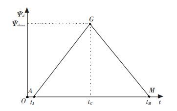 Figure 2 Desired linear reference model of yaw angle
 In Fig. 2,tA,tM and tG correspond to the running time of vehicle at points A,G and M, respectively, and tG-tA=tM-tG. ψdmax is the maximum of desired yaw angle. Assuming that the required time to change lanes is T, then T=tM-tA. Therefore, corresponding to Fig. 2, the desired yaw angle model can be expressed mathematically as
${{\psi }_{d}}\left( t \right)=\left\{ \begin{matrix} 0, t<{{t}_{A}} \\ 2{{\psi }_{d\max }}\left( t-{{t}_{A}} \right)/T,{{t}_{A}}\le t\le {{t}_{G}} \\ 2{{\psi }_{d\max }}\left( {{t}_{M}}-t \right)/T,{{t}_{G}}<t\le {{t}_{M}} \\ 0, t\le {{t}_{M}} \\\end{matrix} \right.$ (2)
From formula (1) and (2), the desired trajectory coordinates of vehicle for lane changing is calculated as follows.
$X\left( t \right)={{X}_{A}}+v\int_{{{t}_{A}}}^{t}{\cos {{\psi }_{d}}\left( t \right)}{{d}_{t}}=$
$\left\{ \begin{matrix} {{X}_{A}}+\frac{vT}{2{{\psi }_{d\max }}}\sin \left( 2{{\psi }_{d\max }}\left( t-{{t}_{A}} \right)/T \right),{{t}_{A}}\le t\le {{t}_{G}} \\ {{X}_{A}}+\frac{vT}{2{{\psi }_{d\max }}}\left[ 2\sin \left( {{\psi }_{d\max }} \right)-\sin \left( 2{{\psi }_{d\max }} \right)\left( {{t}_{M}}-t \right)/T \right],{{t}_{G}}<t\le {{t}_{M}} \\\end{matrix} \right.$ (3)
$Y\left( t \right)={{Y}_{A}}+v\int{\begin{matrix} t \\ {{t}_{A}} \\\end{matrix}}\sin {{\psi }_{d}}\left( t \right)dt=$
$\left\{ \begin{matrix} {{Y}_{A}}+\frac{vT}{2{{\psi }_{d\max }}}\left[ 1-\cos \left( 2{{\psi }_{d\max }}\left( t-{{t}_{A}} \right)/T \right. \right],{{t}_{A}}\le t\le {{t}_{G}} \\ {{Y}_{A}}+\frac{vT}{2{{\psi }_{d\max }}}\left[ 1-2\cos \left( {{\psi }_{d\max }} \right)+\cos \left( 2{{\psi }_{d\max }}\left( {{t}_{M}}-t \right./T \right) \right],{{t}_{G}}\le t\le {{t}_{M}} \\\end{matrix} \right.$ (4)
Deducing from formula (4) , when t = tM , wehave
$Y\left( {{t}_{M}} \right)={{Y}_{A}}+\frac{vT}{{{\psi }_{d\max }}}\left[ 1-\cos \left( {{\psi }_{d\max }} \right) \right]$
according to Y(tM ) - YA = d, we know
$d=\frac{vT}{{{\psi }_{d\max }}}\left[ 1-\cos \left( {{\psi }_{d\max }} \right) \right]$
so the time of changing lanes is obtained as
$T=\frac{d{{\psi }_{d\max }}}{v\left[ 1-\cos \left( {{\psi }_{d\max }} \right) \right]}$ (5)
The curves in Fig. 3 represent the relation between lane changing time T and the maximum of expected yaw angle ψdmax, where the vehicle speed v is 25 m / s, the value of lane spacing d is taken as 3.5,7 and 10.5 m, respectively,ψdmax ranges between 0.1 and π/4 rad. As can be seen from Fig. 3, the greater the ψdmax is, the smaller the time T is.
Figure 3
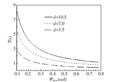 Figure 3 The relation between lane changing time and the maximum of expected yaw angle
 Assuming that the initial lane changing position coordinates XA=0 and YA=0, lane changing time T is 4 s, and speed v is 20 m/s, and lane spacing d is 3.5 m, by formula (5), corresponding maximum of desired yaw angle ψdmax can be obtained as 0.087 555 rad, and expected yaw angle with time variations is shown in Fig. 4, and the corresponding changing lane trajectory is shown in Fig. 5.
Figure 4
 Figure 4 Expected yaw angle for lane changing
 Figure 5
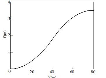 Figure 5 Desired lane changing trajectory
 As can be seen from Fig. 4, yaw angle reference model (2) is a linear model and it is relatively simple. Corresponding yaw rate is easily get as the form
${{\dot{\psi }}_{d}}\left( t \right)=\left\{ \begin{matrix} 0, & t<{{t}_{A}} \\ 2{{\psi }_{d\max }}/T, & {{t}_{A}}\le t\le {{t}_{G}} \\ -2{{\psi }_{d\max }}/T, & {{t}_{G}}<t\le {{t}_{M}} \\ 0, & t>{{t}_{M}} \\\end{matrix} \right.$ (6)
According to formula(6), at start time tA and end time tM in lane changing process, the vehicle yaw rate goes through step change, so if we try to realize lane changing behavior by tracking the reference yaw angle model (2), shock phenomenon would occur in the system. In consideration of safety and comfort, the reference model needs further improvement.
2.2 Nonlinear Yaw Angle Model Using two smooth symmetrical curves to replace lines AG and GM in Fig. 2, expected nonlinear yaw angle reference model diagram can be obtained as Fig. 6.
In Fig. 6, add points D and J to the lane changing trajectory, corresponding time is tD and tJ. In the corresponding curve of expected yaw angle model, the angle between tangential direction and the axis is αD and αJ respectively. As shown in Fig. 6,αD>0 and αJ<0, because $\frac{d{{\psi }_{d}}}{dt}{{\left| _{t={{t}_{D}}}=\tan {{\alpha }_{D}}, and\frac{d{{\psi }_{d}}}{dt} \right|}_{t={{t}_{J}}}}=\tan {{\alpha }_{J}},$, so we get ${{\dot{\psi }}_{d}}\left( {{t}_{D}} \right)>0 $, and ${{\dot{\psi }}_{d}}\left( {{t}_{J}} \right)<0$ The corresponding yaw rate model is shown in Fig. 7 approximately.
Figure 6
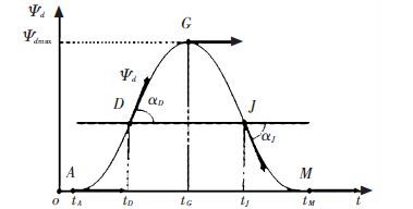 Figure 6 Improved yaw angle reference model for lane changing
 Figure 7
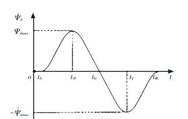 Figure 7 Desired yaw rate for lane changing
 This paper assumes that yaw angular acceleration satisfies trapezoidal constraints during the lane changing process. According to Fig. 7, desired yaw angular acceleration model can be designed as shown in Fig. 8.
Figure 8
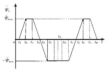 Figure 8 Desired yaw angular acceleration for lane changing
 In Fig. 8,${{\ddot{\psi }}_{d\max }}$ is the maximum of desired yaw angular acceleration, and the time coordinates shown in Fig. 8 satisfies
${{t}_{B}}-{{t}_{A}}={{t}_{D}}-{{t}_{C}}={{t}_{E}}-{{t}_{D}}={{t}_{H}}-{{t}_{F}}={{t}_{J}}-{{t}_{I}}={{t}_{K}}-{{t}_{J}}={{t}_{M}}-{{t}_{L}}$
${{t}_{C}}-{{t}_{B}}={{t}_{F}}-{{t}_{E}}={{t}_{I}}-{{t}_{H}}={{t}_{L}}-{{t}_{K}}$
Noting ${{t}_{B}}-{{t}_{A}}={{T}_{1}}$ and ${{t}_{C}}-{{t}_{B}}={{T}_{2}}$, then the time required for lane changing is $T={{t}_{M}}-{{t}_{A}}=7{{T}_{1}}+4{{T}_{2}}$. According to Fig. 8, the desired yaw angular acceleration model of vehicle can be expressed as the following mathematical formula.
${{{\ddot{\psi }}}_{d}}\left( t \right)=\left\{ -\begin{matrix} 0, & t<{{t}_{A}} \\ {{{\ddot{\psi }}}_{d\max }}\left( t-{{t}_{A}} \right)/{{T}_{1}}, & {{t}_{A}}\le t\le {{t}_{B}} \\ {{{\ddot{\psi }}}_{d\max }}, & {{t}_{B}}<t\le {{t}_{C}} \\ {{{\ddot{\psi }}}_{d\max }}\left( {{t}_{D}}-t \right)/{{T}_{1}}, & {{t}_{C}}<t\le {{t}_{E}} \\ {{{\ddot{\psi }}}_{d\max }}, & {{t}_{E}}<t\le {{t}_{I}} \\ {{{\ddot{\psi }}}_{d\max }}\left( t-{{t}_{J}} \right), & {{t}_{I}}<t\le {{t}_{K}} \\ {{{\ddot{\psi }}}_{d\max }}, & {{t}_{K}}<t\le {{t}_{L}} \\ {{{\ddot{\psi }}}_{d\max }}\left( {{t}_{M}}-t \right)/{{T}_{1}}, & {{t}_{L}}<t\le {{t}_{M}} \\ 0, & t>{{t}_{M}} \\\end{matrix} \right.$ (7)
By integrating formula(7), desired yaw rate model can be obtained as follows.
${{{\ddot{\psi }}}_{d}}\left( t \right)=\left\{ \begin{matrix} 0, & t<{{t}_{A}} \\ {{{\ddot{\psi }}}_{d\max }}{{\left( t-{{t}_{A}} \right)}^{2}}/\left( 2{{T}_{1}} \right), & {{t}_{A}}\le t\le {{t}_{B}} \\ {{{\ddot{\psi }}}_{d\max }}\left( {{T}_{1}}/2+t-{{t}_{B}} \right), & {{t}_{B}}<t\le {{t}_{C}} \\ {{{\ddot{\psi }}}_{d\max }}\left[ {{T}_{1}}+{{T}_{2}}-{{\left( {{t}_{D}}-t \right)}^{2}}/\left( 2{{T}_{1}} \right) \right], & {{t}_{C}}<t\le {{t}_{E}} \\ {{{\ddot{\psi }}}_{d\max }}\left[ {{T}_{1}}/2+{{T}_{2}}-t+{{t}_{E}} \right], &{{t}_{E}}<t\le {{t}_{I}} \\ {{{\ddot{\psi }}}_{d\max }}\left[ -{{T}_{1}}-{{T}_{2}}+{{\left( t-{{t}_{J}} \right)}^{2}}/\left( 2{{T}_{1}} \right) \right], & {{t}_{I}}<t\le {{t}_{K}} \\ {{{\ddot{\psi }}}_{d\max }}\left[ -{{T}_{1}}/2-{{T}_{2}}+t-{{t}_{K}} \right], & {{t}_{K}}<t\le {{t}_{L}} \\ -{{{\ddot{\psi }}}_{d\max }}{{\left( {{t}_{M}}-t \right)}^{2}}/\left( 2{{T}_{1}} \right), & {{t}_{L}}<t\le {{t}_{M}} \\ 0, & t>{{t}_{M}} \\\end{matrix} \right.$ (8)
Further, by integrating formulas (8), the desired yaw angle model can be obtained as the following form.
$\left\{ \begin{align} & 0, t<{{t}_{A}} \\ & {{{\ddot{\psi }}}_{d\max }}{{\left( t-{{t}_{A}} \right)}^{3}}/\left( 6{{T}_{1}} \right), {{t}_{A}}\le t\le {{t}_{B}} \\ & {{{\ddot{\psi }}}_{d\max }}\left[ T_{1}^{2}/6+{{T}_{1}}\left( t-{{t}_{B}} \right)/2+{{\left( t-{{t}_{B}} \right)}^{2}}/2 \right], {{t}_{B}}<t\le {{t}_{C}} \\ & {{{\ddot{\psi }}}_{d\max }}\left[ {{T}_{2}}\left( {{T}_{1}}+{{T}_{2}} \right)/2+\left( {{T}_{1}}+{{T}_{2}} \right)\left( t-{{t}_{C}} \right)+{{\left( {{t}_{D}}-t \right)}^{3}}/\left( 6{{T}_{1}} \right) \right], {{t}_{C}}<t\le {{t}_{E}} \\ & {{{\ddot{\psi }}}_{d\max }}\left[ \left( {{T}_{1}}+{{T}_{2}} \right)\left( {{T}_{2}}/2+2{{T}_{1}} \right)-{{T}_{1}}^{2}/6+\left( {{T}_{1}}/2 \right)+{{T}_{2}}\left( t-{{t}_{E}} \right)-{{\left( t-{{t}_{E}} \right)}^{2}}/2 \right], {{t}_{E}}<t\le {{t}_{I}} \\ & {{{\ddot{\psi }}}_{d\max }}\left[ \left( {{T}_{1}}+{{T}_{2}} \right)\left( {{T}_{2}}/2+2{{T}_{1}} \right)+\left( {{T}_{1}}+{{T}_{2}} \right)\left( {{t}_{I}}-t \right)+{{\left( t-{{t}_{J}} \right)}^{3}}/\left( 6{{T}_{1}} \right) \right], {{t}_{I}}<t\le {{t}_{K}} \\ & {{{\ddot{\psi }}}_{d\max }}\left[ \left( {{T}_{1}}+{{T}_{2}} \right){{T}_{2}}/2+T_{1}^{2}/6+\left( {{T}_{1}}/2+{{T}_{2}} \right)\left( {{t}_{K}}-t \right){{\left( t-{{t}_{K}} \right)}^{2}}/2 \right], {{t}_{K}}<t\le {{t}_{L}} \\ & {{{\ddot{\psi }}}_{d\max }}\left[ {{\left( {{t}_{M}}-t \right)}^{3}}/\left( 6{{T}_{1}} \right) \right], {{t}_{L}}<t\le {{t}_{M}} \\ & 0, t>{{t}_{M}} \\ \end{align} \right.$ (9)
Synthesizing formulas (1) and (9), if the vehicle speed v is known, based on $\int{\begin{matrix} {{t}_{M}} \\ {{t}_{A}} \\\end{matrix}}v\left( t \right)\sin {{\psi }_{d}}\left( t \right)dt=d$, the maximum of desired yaw angular acceleration ${{{\ddot{\psi }}}_{d\max }}$ can be determined.
Assuming that the speed v is 20 m/s, and lane spacing d is 3.5 m, the initial lane changing position coordinates XA=0,YA=0, initial time for lane changing tA=0, lane changing time T is 5 s. Let T1=0.2 s,T2=0.9 s, then we have
$\begin{align} & {{t}_{B}}={{t}_{A}}+{{T}_{1}}=0.2s, {{t}_{C}}={{t}_{A}}+{{T}_{1}}+{{T}_{2}}=1.1s \\ & {{t}_{D}}={{t}_{A}}+2{{T}_{1}}+{{T}_{2}}=1.3s, {{t}_{E}}={{t}_{A}}+3{{T}_{1}}+{{T}_{2}}=1.5s \\ & {{t}_{I}}={{t}_{A}}+4{{T}_{1}}+3{{T}_{2}}=3.5s, {{t}_{J}}={{t}_{A}}+5{{T}_{1}}+3{{T}_{2}}=3.7s \\ & {{t}_{K}}={{t}_{A}}+6{{T}_{1}}+3{{T}_{2}}=3.9s, {{t}_{L}}={{t}_{A}}+6{{T}_{1}}+4{{T}_{2}}=4.8s \\ & {{t}_{M}}={{t}_{A}}+7{{T}_{1}}+4{{T}_{2}}=5s \\ \end{align}$
By formula (9), we obtain
${{\psi }_{d}}\left( t \right)=\left\{ \begin{matrix} 0, & t<0 \\ {{{\ddot{\psi }}}_{d\max }}{{t}^{3}}/1.2, & 0\le t\le 0.2 \\ {{{\ddot{\psi }}}_{d\max }}\left[ 0.02/3+0.1\left( t-0.2 \right)+0.5{{\left( t-0.2 \right)}^{2}} \right], & 0.2<t\le 1.1 \\ {{{\ddot{\psi }}}_{d\max }}\left[ 0.495+1.1\left( t-1.1 \right)+{{\left( 1.3-t \right)}^{3}}/1.2 \right], & 1.1<t\le 1.5 \\ {{{\ddot{\psi }}}_{d\max }}\left[ 2.785/3+\left( t-1.5 \right)-0.5{{\left( t-1.5 \right)}^{2}} \right], & 1.5<t\le 3.5 \\ {{{\ddot{\psi }}}_{d\max }}\left[ 0.935+1.1\left( 3.5-t \right)+{{\left( t-3.7 \right)}^{3}}/1.2 \right], & 3.5<t\le 3.9 \\ {{{\ddot{\psi }}}_{d\max }}\left[ 1.505/3+\left( 3.9-t \right)+0.5{{\left( t-3.9 \right)}^{2}} \right], & 3.9<t\le 4.8 \\ {{{\ddot{\psi }}}_{d\max }}\left[ {{\left( 5-t \right)}^{3}}/1.2 \right], & 4.8<t\le 5 \\ 0, & t>5 \\\end{matrix} \right.$ (10)
According to$\int{\begin{matrix} 5 \\ 0 \\\end{matrix}}20sin{{\psi }_{d}}\left( t \right)dt=3.5$, taking formula (10) into it and calculating the maximum desired yaw angular acceleration, we get ψdmax=0.051 02 rad·s-2, then by using formulas (7),(8) and (10), reference value of desired yaw angular acceleration, yaw rate and yaw angle can be easily calculated. On the base of $X\left( t \right)=\int{\begin{matrix} t \\ 0 \\\end{matrix}}20\cos {{\psi }_{d}}\left( t \right)dt$, and $Y\left( t \right)=\int{\begin{matrix} t \\ 0 \\\end{matrix}}20\sin {{\psi }_{d}}\left( t \right)dt,0\le t\le 5$, we get the trajectory coordinates for lane changing. Simulation results are shown in Fig. 9.
Figure 9
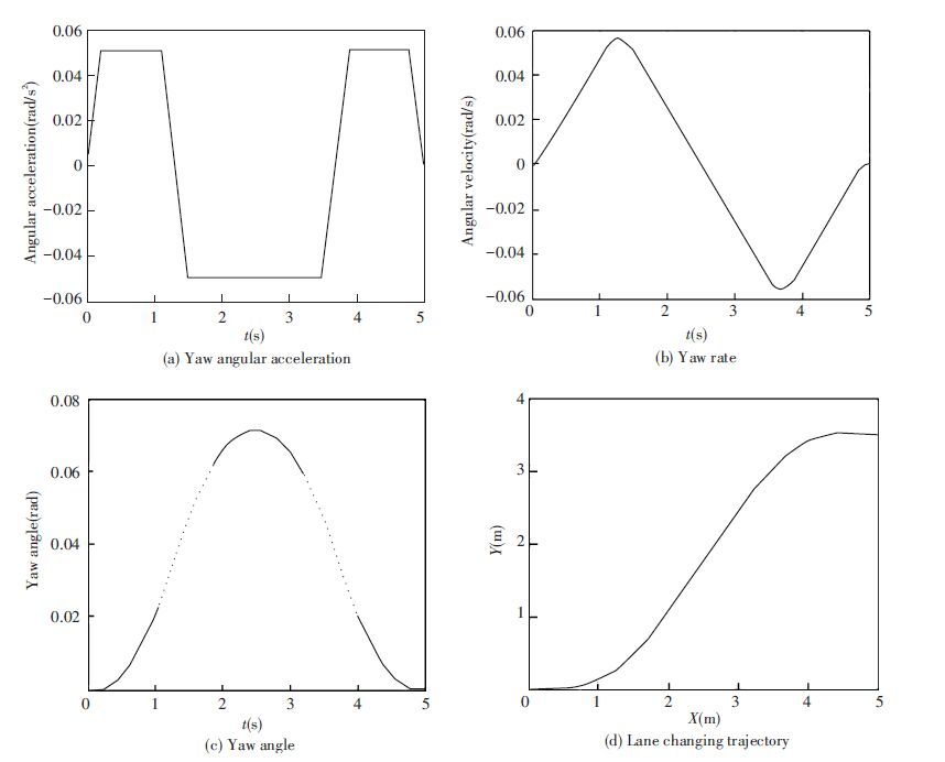 Figure 9 Lane changing model using the positive and negative trapezoidal yaw angular acceleration
 2.3 Model ComparisonRefs.[9] and [17] studied lane changing control of vehicles on the base of yaw angle tracking, assuming that the vehicle’s longitudinal velocity is constant, and expected lateral acceleration satisfies both positive and negative trapezoidal constraints, the expected rate of lateral acceleration is defined as shown in Fig. 10.
Figure 10
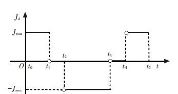 Figure 10 Expected rate of lateral acceleration in lane changing
 In Fig. 10,Jd(t) represents the expected rate of lateral acceleration; Jmax represents the maximum of rate of expected lateral acceleration, which can be determined by time requirements of lane changing and lane spacing; t0 represents the start time of lane changing; t5 is the end time of lane changing. t1,t2,t3and t4 are the four critical time during lane changing process which satisfy the following constraints:
t1-t0=t5-t4, t4-t3=t2-t1, t3-t2=2(t1-t0).
Noting t1-t0=Δ1,t2-t1=Δ2, then the time required for lane changing is T=t5-t0=4Δ1+2Δ2. Assuming that the start time of lane changing t0 is 0, then Jmax can be calculated by $\int{\begin{matrix} {{t}_{5}} \\ 0 \\\end{matrix}}\int{\begin{matrix} \beta \\ 0 \\\end{matrix}}\int{\begin{matrix} \alpha \\ 0 \\\end{matrix}}{{J}_{d}}\left( \tau \right)d\tau d\alpha d\beta =d$, where α and β are the integral variables.
Correspondingly, the desired yaw angle, yaw rate and yaw angle acceleration can be calculated by the following formula.
$\left\{ \begin{matrix} {{\psi }_{d}}\left( t \right)=\frac{1}{v}\int{\begin{matrix} t \\ 0 \\\end{matrix}\int{\begin{matrix} \beta \\ 0 \\\end{matrix}{{J}_{d}}\left( \tau \right)d\tau d\beta }} \\ {{{\dot{\psi }}}_{d}}\left( t \right)=\frac{1}{v}\int{\begin{matrix} t \\ 0 \\\end{matrix}{{J}_{d}}\left( \tau \right)d\tau } \\ {{{\ddot{\psi }}}_{d}}\left( t \right)=\frac{{{J}_{d}}\left( t \right)}{v} \\\end{matrix} \right.$ (11)
Assuming speed v is 20 m/s, lane spacing d is 3.5 m, lane changing time T is 5 s, let Δ1=2Δ2, according to Fig. 10, the value of Jmax is obtained as 0.932 89 m·s-3. Then the desired yaw angular acceleration, yaw rate and yaw angle reference values are obtained by formula (11). Simulation results are shown in Fig. 11.
Figure 11
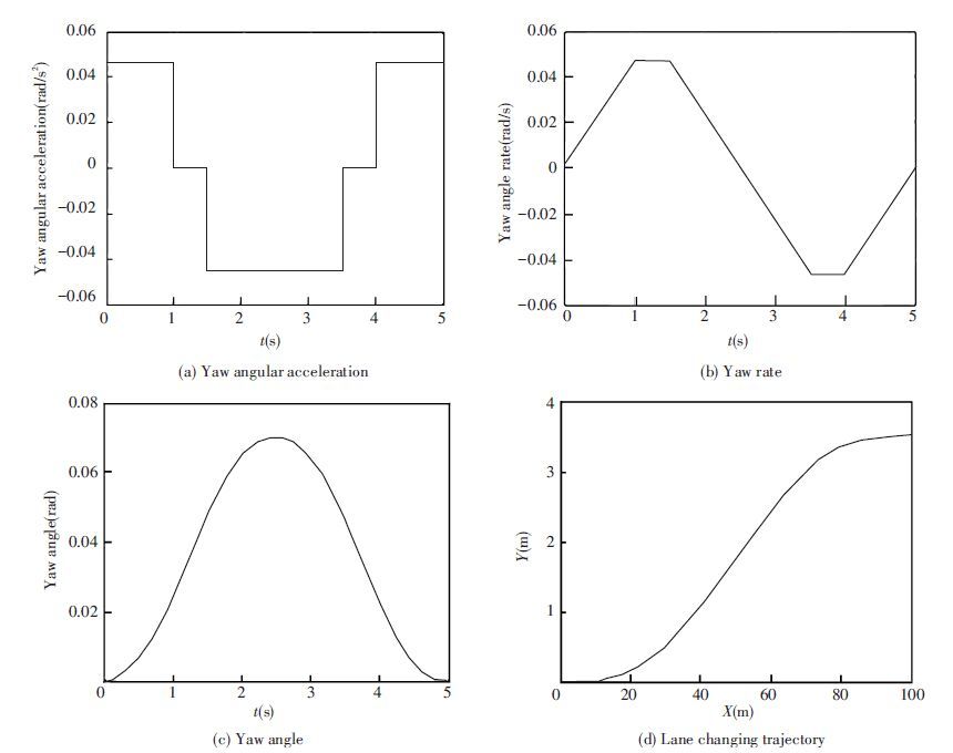 Figure 11 Lane changing model using positive and negative trapezoidal lateral acceleration
 According to Fig. 10, there exists discontinuity points of Jd(t) in the lane changing process at the time t1,t2,t3 and t4. Accordingly, the desired yaw angular acceleration in lane changing process calculated by formula (11) is not continuous, as shown in Fig. 11(a) .
Here we design a yaw angle tracking control law to compare the difference of vehicle steering angle when using the above two vehicle lane changing models. Regardless of road roll, pitch and other factors, ignoring air resistance, the vehicle’s lateral dynamic equations are simplified as follows[18].
$\ddot{\psi }=-\frac{2\left( {{C}_{f}}l_{f}^{2}+{{C}_{r}}l_{r}^{2} \right)}{{{I}_{z}}{{v}_{x}}}\dot{\psi }-\frac{2\left( {{C}_{f}}{{l}_{f}}+{{C}_{r}}{{l}_{r}} \right)}{{{I}_{z}}{{v}_{x}}}{{v}_{y}}+\frac{2{{C}_{f}}{{l}_{f}}}{{{I}_{z}}}{{\delta }_{f}}$ (12)
$\dot{v}=-\frac{2\left( {{C}_{f}}+{{C}_{r}} \right)}{m{{v}_{x}}}{{v}_{y}}-\left[ {{v}_{x}}+\frac{2\left( {{C}_{f}}{{l}_{f}}+{{C}_{r}}{{l}_{r}} \right)}{m{{v}_{x}}} \right]\dot{\psi }+\frac{2{{C}_{f}}}{m}{{\delta }_{f}}$ (13)
where ψ represents the vehicle yaw angle; m is the vehicle mass; Iz represents inertia of vehicle around the vertical axis; vx,vy respectively represent longitudinal and lateral velocity in vehicle body coordinate system; lfand lr respectively represent distance from centroid to the front axle and rear axle; Cf and Cr respectively represent the cornering stiffness of the front and rear tires; δf represents steering angle of the front wheel.
Defining the tracking error of yaw angle as ψr(t)=ψ(t)-ψd(t), using the switching function as $s={{{\dot{\psi }}}_{r}}\left( t \right)+k{{\psi }_{r}}\left( t \right)$, where k>0. By sliding mode method, the steering angle of vehicle can be designed as
${{\delta }_{f}}=\frac{{{l}_{z}}}{2{{C}_{f}}{{l}_{f}}}\left[ {{{\ddot{\psi }}}_{d}}\left( t \right)-k{{{\dot{\psi }}}_{r}}\left( t \right)+\frac{2\left( {{C}_{f}}l_{f}^{2}+{{C}_{r}}l_{r}^{2} \right)}{{{l}_{z}}{{v}_{x}}}+\dot{\psi }+\frac{2\left( {{C}_{f}}{{l}_{f}}+{{C}_{r}}{{l}_{r}} \right)}{{{l}_{z}}{{v}_{x}}}{{v}_{y}}-\lambda s \right]$ (14)
where λ>0. In fact, the control input will also be affected by the change of the adhesion coefficient of road, so the actual control system design for lane changing should also consider to estimate the adhesion coefficient of road.
In the simulation, it is assumed that the vehicle mass m is 1 500 kg, inertia Iz is 3 000 kg·m2, cornering stiffness of front and rear tires Cf and Cr are 70 000 and 80 000 N/rad, respectively. The distance from centroid to the front axle lf is 1.4 m, distance from centroid to the rear axle lr is 1.3 m. Initial value of lateral velocity vy is 0 m/s, initial value of the vehicle yaw angle ψ is 0 rad, initial value of yaw rate $\dot{\psi }$ is 0 rad/s. Control parameter k is set to 0.5,λ to 50. The tracking error and control input using two yaw angle reference model are shown in Figs. 12 and 13. In Figs. 12 and 13, curve ① shows results obtained based on the positive and negative trapezoid lateral acceleration; curve ② shows results obtained based on the forward and reverse trapezoid yaw angular acceleration. It can be seen that if method ① is used, desired steering angle has step changes, which are difficult to achieve in engineering, and if method ② is used, the curve of steering angle is continuous and smooth.
Figure 12
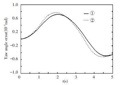 Figure 12 Yaw angle tracking error
 Figure 13
 Figure 13 Control input
 3 Lane Change Reference Model on Circular Road3.1 Model Planning For Yaw AngleConsidering the situation when road curvature is not 0, we assume that two lane centerlines have the same instantaneous center, radius of curvature of the outer lane is C, lane spacing still denoted by d. Fig. 14 is a planning schematic diagram about desired yaw angle of lane changing. Bipartite graph (a) and (b) correspond to two cases of lane changing: from the outside lane to the inside lane and the opposite. In Fig. 14,Xc and Yc respectively represent horizontal and vertical axis in the global coordinate system; C represents the vehicle’s center of mass; OR represents the instantaneous center of the road; ψd_c represents desired yaw angle of lane changing round about; θ represent angle about the vehicle’s mass center turning around OR; ρ represents the vehicle’s instantaneous radius when its mass center turns around OR.
Figure 14
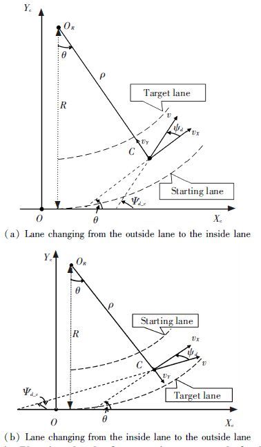 Figure 14 Planning sketch of expectations yaw angle for lane changing on circular road
 When vehicle changes lanes from the outside to the inside lane, according to Fig. 14(a), we can obtain
$\rho \left( t \right)=R-\int{\begin{matrix} t \\ 0 \\\end{matrix}}{{v}_{Y}}\left( \sigma \right)d\sigma =R-\int{\begin{matrix} t \\ 0 \\\end{matrix}}v\sin \left( {{\psi }_{d}}\left( \sigma \right) \right)d\sigma $
Assuming vehicle speed is A constant, so
$\theta \left( t \right)=\int{\begin{matrix} t \\ {{t}_{A}} \\\end{matrix}}\frac{{{v}_{X}}\left( \tau \right)}{\rho \left( \tau \right)}d\tau =\int{\begin{matrix} t \\ {{t}_{A}} \\\end{matrix}\frac{v\cos \left( {{\psi }_{d}}\left( \tau \right) \right)}{R-\int{\begin{matrix} \tau \\ 0 \\\end{matrix}v\sin \left( {{\psi }_{d}}\left( \sigma \right) \right)d\sigma }}}d\tau $
$\theta \left( t \right)=\frac{v\cos \left( {{\psi }_{d}}\left( t \right) \right)}{R-\int{\begin{matrix} t \\ {{t}_{A}} \\\end{matrix}v\sin \left( {{\psi }_{d}}\left( \sigma \right) \right)d\sigma }}$
$\begin{array}{l}\theta \left( t \right) = \\ - v{\psi _d}\left( t \right)\sin \left( {{\psi _d}\left( t \right)} \right)\left[ {R - \smallint \begin{array}{*{20}{c}}t\\{{t_A}}\end{array}v\sin \left( {{\psi _{d\left( \sigma \right)}}} \right)d\sigma + {v^2}\sin \left( {{\psi _d}\left( t \right)} \right)} \right]/{\left[ {R - \smallint \begin{array}{*{20}{c}}t\\{{t_A}}\end{array}v\sin \left( {{\psi _{d\left( \sigma \right)}}} \right)d\sigma } \right]^2}\end{array}$
According to Fig. 14(a), when the vehicle changes lanes from the outside lane to the inside, the vehicle desired yaw angle, yaw rate and yaw angular acceleration can be calculated as the following equations.
$\begin{align} & {{\psi }_{d\_c}}\left( t \right)={{\psi }_{d}}\left( t \right)+\theta \left( t \right) \\ & {{{\dot{\psi }}}_{d\_c}}\left( t \right)={{{\dot{\psi }}}_{d}}\left( t \right)+\dot{\theta }\left( t \right) \\ & {{{\ddot{\psi }}}_{d\_c}}\left( t \right)={{{\ddot{\psi }}}_{d}}\left( t \right)+\ddot{\theta }\left( t \right) \\ \end{align}$ (15)
When the vehicle changes lanes from the inside lane to the outside, according to Fig. 14(b), we can obtain
$\rho \left( t \right)=R-d=\int{\begin{matrix} t \\ 0 \\\end{matrix}{{v}_{Y}}\left( \sigma \right)}d\sigma =R-d+\int{\begin{matrix} t \\ 0 \\\end{matrix}v\sin }\left( {{\psi }_{d}}\left( \sigma \right) \right)d\sigma $
So
$\theta \left( t \right)=\int{\begin{matrix} t \\ {{t}_{A}} \\\end{matrix}}\frac{v\cos \left( {{\psi }_{d}}\left( \tau \right) \right)}{R-d+\int{\begin{matrix} \tau \\ {{t}_{A}} \\\end{matrix}v\sin }\left( {{\psi }_{d}}\left( \sigma \right) \right)d\sigma }d\tau $
$\dot{\theta }\left( t \right)=\frac{v\cos \left( {{\psi }_{d}}\left( t \right) \right)}{R-d+\int{\begin{matrix} t \\ {{t}_{A}} \\\end{matrix}v\sin }\left( {{\psi }_{d}}\left( \sigma \right) \right)d\sigma }$
$\begin{array}{l}\ddot \theta \left( t \right) = - v{{\dot \psi }_d}\left( t \right)\sin \left( {{\psi _d}\left( t \right)} \right)\left[ {R - d + \smallint \begin{array}{*{20}{c}}t\\{{t_A}}\end{array}v\sin \left( {{\psi _d}\left( \sigma \right)} \right)d\sigma } \right] - \\{v^2}\sin \left( {{\psi _d}\left( t \right)} \right)\left. {\cos \left( {{\psi _d}\left( t \right)} \right)} \right]/{\left[ {R - d + \smallint \begin{array}{*{20}{c}}t\\{{t_A}}\end{array}v\sin \left( {{\psi _d}\left( \sigma \right)} \right)d\sigma } \right]^2}\end{array}$
According to Fig. 14(b), when the vehicle changes lanes from the inside lane to the outside, the vehicle desired yaw angle, yaw rate and yaw angular acceleration can be calculated as the following equations.
$\begin{align} & {{\psi }_{d\_c}}\left( t \right)=-{{\psi }_{d}}\left( t \right)+\theta \left( t \right) \\ & {{{\dot{\psi }}}_{d\_c}}\left( t \right)=-{{{\dot{\psi }}}_{d}}\left( t \right)+\dot{\theta }\left( t \right) \\ & {{{\ddot{\psi }}}_{d\_c}}\left( t \right)=-{{{\ddot{\psi }}}_{d}}\left( t \right)+\ddot{\theta }\left( t \right) \\ \end{align}$ (16)
The lane changing process on circular road is simulated according to formulas (15) and (16). Fig. 15 shows the simulation results when the vehicle change lanes from the outside lane to the inside lane. In the simulation,R is 100 m, d is 3.5 m, and v is 20 m/s. Figs. 15(a),Figs. 15(b) and Figs. 15(c) reflect the relevance of yaw angle reference model between lane changing on circular road and lane changing on straight road. Fig. 15(d) shows the resulting lane changing trajectory curve using yaw angle reference model (15).
Figure 15
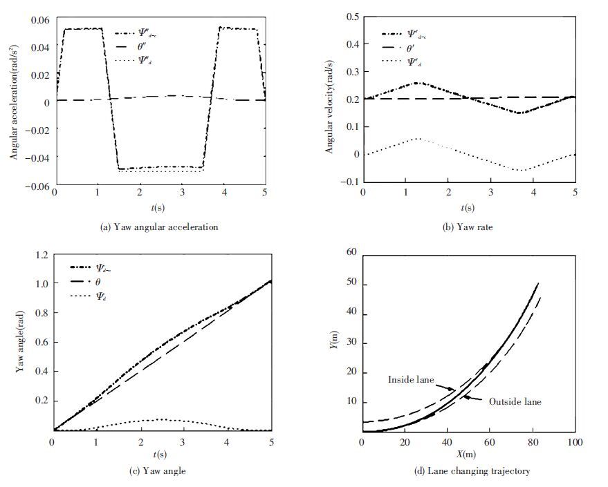 Figure 15 Lane changing model on circular road
 3.2 Model Comparison For Yaw AngleRef.[17] studied the lane changing based on the desired lateral acceleration constraint, and the control law is designed by yaw angle tracking, as vehicle lane changing on circular road, expected yaw angle and yaw rate are calculated using the following method:
$\left\{ \begin{matrix} {{\psi }_{d}}\left( t \right)={{v}_{x}}xt+\frac{1}{{{v}_{x}}}\int{\begin{matrix} t \\ 0 \\\end{matrix}\int{\begin{matrix} \beta \\ 0 \\\end{matrix}}}{{J}_{d}}\left( \tau \right)d\tau d\beta \\ {{{\dot{\psi }}}_{d}}\left( t \right)={{v}_{x}}x+\frac{1}{{{v}_{x}}}\int{\begin{matrix} t \\ 0 \\\end{matrix}}{{J}_{d}}\left( \tau \right)d\tau \\\end{matrix} \right.$ (17)
Informulas above,χ refers to the road curvature; vxχrepresents rotation angular velocity of the vehicle around the instantaneous center of the road, that is ${\dot{\theta }}$; vxχt represents the rotation angle of the vehicle around the instantaneous center of road, that is θ. Using trajectory planning method based on expected lateral acceleration rate, the desired yaw rate and yaw angles are approximated by the formula $\frac{1}{{{v}_{x}}}\int{\begin{matrix} t \\ 0 \\\end{matrix}\int{\begin{matrix} \beta \\ 0 \\\end{matrix}}}{{J}_{d}}\left( \tau \right)d\tau d\beta $ and $\frac{1}{{{v}_{x}}}\int{\begin{matrix} t \\ 0 \\\end{matrix}}{{J}_{d}}\left( \tau \right)d\tau $. As can be seen, without considering the difference between the radius of curvature of the two lanes, i.e., assuming that the distance between instantaneous center of the road and the vehicle is constant in lane changing process, results lane changing trajectory exists deviation. Simulation results are shown in Fig. 16, where curve ① represents the results obtained by using formula (17), and curve ② represents results obtained by using formula (15), respectively. From Fig. 16(a), we can see that if formula (17) is used, the position of the vehicle’s mass center will not be in the target lane at the end of lane changing process, so there is a departure in the resulting trajectory model. If formula (15) is used, the position of the vehicle’s mass center coincides with the target lane, there is no deviation. Fig. 16(b) shows changes of the vehicle positional deviation in the process of lane changing. By applying formula (17), when the time is 3.78 s, the offset is 0, and the deviation is approximately 0.62 m at the end of lane changing, which illustrates that the vehicle lateral displacement exceeds lane spacing, while using formula (15), the deviation of vehicle position is 0 at the end of lane changing process. Fig. 16(c) shows the changes of the yaw angle in the process of lane changing. In the simulation,R is 100 m,d is 7 m, and v is 15 m/s.
Figure 16
 Figure 16 Comparison about lane changing model on circular road
 Refs.[19-21] studied lane changing on circular road based on the Ref.[17], considering the difference between the radius of curvature of two lanes, from synthesizing expected translational state when vehicles change lanes in straight road and the rotation when their mass centers turn around the instantaneous center of the road, calculated vertical and horizontal movement state of vehicles on the circular road. To calculate a desired yaw rate and the yaw angle based on vertical and horizontal motion of the vehicle is very complex. Due to the application of trajectory planning method based on positive and negative trapezoidal lateral acceleration, the expected yaw angular acceleration is not continuous, and there are step changes, which can be seen from Fig. 17. This paper plans lane change trajectory on the circular lane based on yaw angular acceleration model, and yaw angle reference model is obtained by algebraic sum of lane changing reference model in straight road and rotation model of vehicle turning around instantaneous center of the road. It is convenient for calculation, and can be seen from Fig. 15(a), that the yaw angular acceleration is continuous.
Figure 17
 Figure 17 Yaw angular acceleration using trapezoidal lateral acceleration constraints for lane changing on circular road
 Similar to the above, the simulation for vehicles change lanes from the inside lane to the outside lane is also done, and the simulation results show the same effectiveness of the trajectory planning method proposed in this paper.
4 Conclusions1) A reference model of yaw motion for lane changing is planned directly according to the movement characteristics of vehicle in the lane changing scenario, this will simplify the calculation of yaw angle tracking for a changing lanes behavior, and eliminate the steps of calculating expected yaw angle, yaw rate and yaw angular acceleration according to the desired lane changing trajectory.
2) If lane changing trajectory is planned based on positive and negative trapezoid lateral acceleration, the resulting expected yaw angular acceleration is not continuous, the steering angle has step changes and the control is difficult to achieve. While using positive and negative trapezoidal yaw acceleration reference model directly, the steering angle of vehicle is continuous.
3) On the circular road, lane changing can be divided into two cases, in which the vehicle changes from the outside lane to the inside and from the inside lane to the outside, respectively. In both cases, the reference model of yaw angle for lane changing can be obtained by computing algebraic sum of reference model of yaw angle for lane changing on straight lanes and rotation model of vehicle around the road instantaneous center.
4) This paper only studies the yaw angle reference model for lane changing, without considering the implementation process of the lane changing behavior. Next, we will consider the influence of following behavior of vehicle on the lane changing process, as well as design a real-time modification method of reference model of yaw angle for lane changing behavior.
References
[1]Giulio E C. Day-to-day dynamic models for Intelligent Transportation Systems design and appraisal.Transportation Research Part C,2013, 29: 117-130.(
 0)
0)[2]Mohammad A, Alicia D, Max K, et al. Longitudinal and lateral control in automated highway systems: their past, present and future.Lecture Notes in Computer Science,2011, 7: 589-598.(
 0)
0)[3]Knoop V L, Buisson C. Calibration and validation of probabilistic discretionary lane-change models.IEEE Transactions on Intelligent Transportation Systems,2015, 16(2): 834-843.(
 0)
0)[4]Knoop V L, Wilson R.E, Buisson C, et al. Number of lane changes determined by splashover effects in loop detector counts.IEEE Transactions on Intelligent Transportation Systems,2012, 13(4): 1525-1534.(
 0)
0)[5]Ho M L, Chan P T, Rad A B. Lane change algorithm for autonomous vehicles via virtual curvature method.Journal of Advanced Transportation,2009, 43(1): 47-70.(
 0)
0)[6]Rahman M, Chowdhury M, Xie Y C, et al. Review of microscopic lane changing models and future research opportunities.IEEE Transactions on Intelligent Transportation Systems,2013, 14(4): 1942-1956.(
 0)
0)[7]Rajamani R, Tan H S, Law B K, et al. Demonstration of integrated longitudinal and lateral control for the operation of automated vehicles in platoons.IEEE Transactions on Control Systems Technology,2000, 8(4): 695-708.(
 0)
0)[8]Yang Zhigang, Qi Zhijin, Huang Yan, et al. Trajectory planning of lane changing for intelligent vehicles.Journal of Chongqing Jiaotong University ( Natural Science),2013, 32(3): 520-524.(
 0)
0)[9]Feng Jinxiang, Ruan Jiuhong, Li Yibin. Study on intelligent vehicle lane change path planning and control simulation. Proceedings of the IEEE International Conference on Information Acquisition. Weihai, 2006. 683-688.
Feng Jinxiang, Ruan Jiuhong, Li Yibin. Study on intelligent vehicle lane change path planning and control simulation. Proceedings of the IEEE International Conference on Information Acquisition. Weihai, 2006. 683-688. (
 0)
0)[10]Chen Jiajia, Zhao Pan, Mei Tao, et al. Lane change path planning based on piecewise Bezier curve for autonomous vehicle. Proceedings of the IEEE International Conference on Vehicular Electronics and Safety. Dongguan, 2013.17-22.
Chen Jiajia, Zhao Pan, Mei Tao, et al. Lane change path planning based on piecewise Bezier curve for autonomous vehicle. Proceedings of the IEEE International Conference on Vehicular Electronics and Safety. Dongguan, 2013.17-22. (
 0)
0)[11]Li Wei, Wang Jing, Duan Jianmin. Lane changing trajectory planning of intelligent vehicles based on polynomials.Computer Engineering and Applications,2012, 48(3): 42-245.(
 0)
0)[12]Hou Y, Edara P, Sun C. Modeling mandatory lane changing using bayes classifier and decision trees.IEEE Transactions on Intelligent Transportation Systems,2014, 15(2): 647-655.(
 0)
0)[13]Yang Xiaobao. A lane changing model considering the maneuver process and its applications.Acta Physica Sinica,2009, 58(2): 836-842.(
 0)
0)[14]Xu Guoqing, Liu Li, Ou Yongsheng, et al. Dynamic modeling of driver control strategy of lane-change behavior and trajectory planning for collision prediction.IEEE Transactions on Intelligent Transportation Systems,2012, 13(3): 1138-1155.(
 0)
0)[15]Zhao Hantao, Mao Hongyan. Cellular automaton simulation of muti-lane traffic flow including emergency vehicle.Acta Physica Sinica,2013, 62(6): 060501.(
 0)
0)[16]Tan H S, Guldner J, Chen C, et al. Lane changing maneuvers with look?down reference systems on automated highways.Control Engineering Practice,2000, 8(9): 1033-1043.(
 0)
0)[17]Hatipoglu C, Ozguner U, Redmill K. Automated lane change controller design.IEEE Transactions on Intelligent Transportation Systems,2003, 4(1): 13-22.(
 0)
0)[18]Rajamani R.. Vehicle Dynamics and Control..New York: Springer, 2006: 43-46.(
 0)
0)[19]Ren Dianbo, Zhang Jiye, Zhang Jingming, et al. Trajectory planning and yaw rate tracking control for lane changing of intelligent vehicle on curved road.Science China Technological Sciences,2011, 54(3): 630-642.(
 0)
0)[20]Guo Lie, Huang Xiaohui, Ge Pingshu, et al. Lane changing trajectory tracking control for intelligent vehicle on curved road based on backstepping.Journal of Jilin University (Engineering and Technology Edition),2013, 43(2): 323-328.(
 0)
0)[21]Guo Lie, Ge Pingshu, Yue Ming, et al. Lane changing trajectory planning and tracking controller design for intelligent vehicle running on curved road.Mathematical Problems in Engineering,2014, 3(6): 1-9.(
 0)
0)