Chao Ming1, Ruisheng Sun1and Chuanjie Sun2
(1.School of Energy and Power Engineering, Nanjing University of Science and Technology, Nanjing 210094, China; 2.Institute of Structural Mechanics, China Academy of Engineering Physics, Mianyang 621900,Sichuan, China)
Abstract:
In this paper, an optimal guidance law for missiles with impact angle and miss distance constraints is proposed to achieve the maximal terminal velocity. The normal acceleration command that includes the time-varying coefficients is introduced to satisfy the desired impact angle as well as zero miss distance according to the geometric relation and relative motion parameters between missile and target. The problem is formulated as an optimal control problem by defining the angle of velocity error and flight-path angle as state variables and maximizing a performance index of the terminal velocity. The analytical form of the proposed guidance law is obtained as the solution of the optimal control problem combining optimal control theory and numerical value computation method. Nonlinear simulations of various situations demonstrate the performance and feasibility of the proposed optimal guidance law.
Key words: optimal guidance law maximum terminal velocity missiles impact angle and miss distance constraints analytical form
DOI:10.11916/j.issn.1005-9113.2016.02.011
Clc Number:V11 TJ765.3
Fund:
Ming Chao, Sun Ruisheng, Sun Chuanjie. Optimal Guidance Law to Maximize Terminal Velocity for Missiles with Impact Angle Constraint[J]. Journal of Harbin Institute of Technology, 2016, 23(2): 72-78. DOI: 10.11916/j.issn.1005-9113.2016.02.011.

Fund the National Security Academic Foundation (Grant No.11176012), and the CALT University Joint innovation Foundation (Grant No.CALT 201302) Corresponding author E-mail:srscom@163.com Article history Received: Apr 10, 2015
Contents Abstract Full text Figures/Tables PDF
Optimal Guidance Law to Maximize Terminal Velocity for Missiles with Impact Angle Constraint
Ming Chao1, Sun Ruisheng1

 , Sun Chuanjie2
 1. School of Energy and Power Engineering, Nanjing University of Science and Technology, Nanjing 210094, China;
2. Institute of Structural Mechanics, China Academy of Engineering Physics, Mianyang 621900, Sichuan, China
Received: Apr 10, 2015
fund: the National Security Academic Foundation (Grant No.11176012), and the CALT University Joint innovation Foundation (Grant No.CALT 201302)
Corresponding author: E-mail:srscom@163.com
Abstract: In this paper, an optimal guidance law for missiles with impact angle and miss distance constraints is proposed to achieve the maximal terminal velocity. The normal acceleration command that includes the time-varying coefficients is introduced to satisfy the desired impact angle as well as zero miss distance according to the geometric relation and relative motion parameters between missile and target. The problem is formulated as an optimal control problem by defining the angle of velocity error and flight-path angle as state variables and maximizing a performance index of the terminal velocity. The analytical form of the proposed guidance law is obtained as the solution of the optimal control problem combining optimal control theory and numerical value computation method. Nonlinear simulations of various situations demonstrate the performance and feasibility of the proposed optimal guidance law.
Key words: optimal guidance law maximum terminal velocity missiles impact angle and miss distance constraints analytical form
1 IntroductionModern missiles are becoming accurate and intelligent with the development of technology and control theory. When the missile homes in on the target and the warhead in detonated until intercept occurs, in order to increase effect of missile warhead, the impact angle and miss distance are important constraints for a missile’s guidance problem as well as the maximum terminal velocity. Hence, the researches on the guidance law of missile play a vital role on improving the damage effectiveness.
Guidance law design of weapon system is a computationally and conceptually demanding problem[1] . To increase the effectiveness of missile system, impact angle control as a part of trajectory modulation is required in the terminal phase together with selection of an effective warhead type. Impact angle control is also needed to enhance survivability of the missiles against defense systems. Moreover, vertical impact on target improves the miss distance due to the navigation error. For these reasons, a few studies on this field have been performed. Since impact-angle constrained problem on maneuvering missile was introduced by Kim and Grider[2] for the first time, domestic and international scholars had developed relevant researches on the optimal guidance law with constrains and made a lot of achievements[3-8] .Meanwhile, in order to adapt to the changes of a combat model and combat environment, the obstacle avoidance technique[9] and the cooperative guidance problem [10] had attracted a wide spread attention in recent years. Lee[11] introduced the missile dynamic characteristics into the guidance equation in the special situation which was on the first-order dynamic delay and obtained the optimal guidance law with impact angle control. Jeong[12] designed the biased proportional navigation guidance law by means of the conditions that the terminal line-of-sight rate and the angle deviation were equal to zero in dimensional plane. Harl [13] presented a sliding mode based impact time and angle guidance law by introducing a line-of-sight rate shaping process, in which the parameter must be tuned by hand or by off-line iterative routine.Zhang [14] developed a guidance laws with impact angle constraint based on integral sliding mode control and nonlinear disturbance observer theory. However, in recent studies on optimal guidance law with constrained conditions, there are few research works on guidance law design that the terminal velocity maximum and terminal constraints can be controlled at intercept.
In this paper, an analytical formulation of velocity maximization optimal guidance law for missile is proposed to achieve a desired impact angle as well as zero miss distance. We note that the guidance command becomes a nonlinear acceleration response of the missile to satisfy the constraints of impact angle and miss distance reference to the basic structure of guidance law in Ref.[15] , and the guidance law design is transformed into optimal control problem by approximating the system to be linear, in which the performance index needs to be maximized. By using optimal control theory and numerical value computation method, optimal guidance law solutions for the missile system are then derived. Finally, the simulations are performed to indicate the performance and feasibility of the proposed optimal guidance law.
2 Problem FormulationAccording to the working process of the missile, the optimal guidance law is studied in the vertical plane and horizontal plane separately. The horizontal motion is a small variable quantity compared to the vertical motion, and thus the optimal guidance law can be investigated independently in the vertical plane by neglecting the movement coupling of these two planes. The main purpose of this paper is to derive the optimal guidance law in the vertical plane. As for the horizontal guidance law, it can be obtained similarly. The geometric motion relation of the missile and the target is shown in Fig. 1.
Figure 1
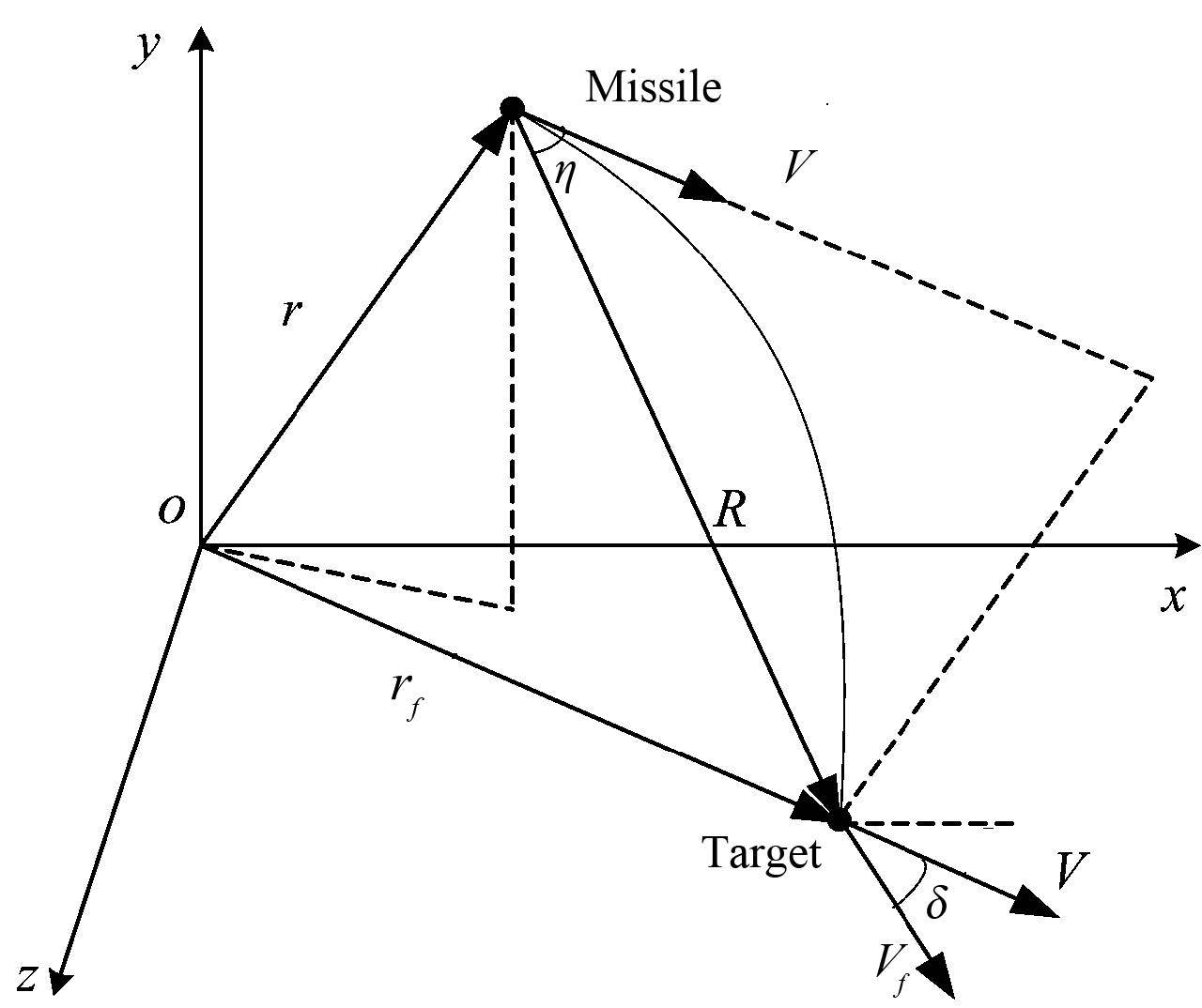 Figure 1 Intercept geometry
 As shown in Fig. 1, the variables r and rf are the position vectors of the missile and target respectively; the variable R is range vector from the missile to the target; the variables V and Vf are vectors of the present velocity and terminal expected velocity when the missile intercepts target, the variable δ is the angle of velocity error between the present and terminal velocity vector and η is the heading angle. In order to satisfy the terminal constraint conditions of the tf , rf and Vf , the acceleration command ac can be obtained as (see derivation in Ref.[15] for details):
${{a}_{c}}=({{K}_{1}}/{{t}_{g}})({{V}_{f}}-V)+({{K}_{2}}/t_{g}^{2})({{r}_{f}}-r-V{{t}_{g}})$ (1)
where K1 and K2 are the proportional coefficients; time to go is tg =tf - t; the acceleration command ac is projected at the normal direction and then the normal acceleration anc is written as:
${{a}_{nc}}=\left( {{K}_{1}}/R \right){{V}^{2}}sin \delta cos \eta -\left( {{K}_{2}}/R \right){{V}^{2}}sin \eta $ (2)
In the vertical plane, we can obtain the relationship among angle of velocity error δ, heading angle η, flight-path angle θ and target-missile line of line-of-sight of angle q from the geometry relation in Fig. 1:
$\delta ={{\theta }_{f}}-\theta \text{ }$ (3)
$\eta =\theta +q$ (4)
Relative motion equations of the missile and the target are summarized as follows:
$\left\{ \begin{align} & \dot{R}=-V\text{cos}\eta \\ & \dot{q}=V\text{sin}\eta /R\text{ } \\ \end{align} \right.$ (5)
Introducing the curvature of the trajectory κ:
$\kappa =d\theta /ds=\dot{\theta }/V$ (6)
By substituting
$\kappa =d\theta /ds=\dot{\theta }/V={{a}_{nc}}/{{V}^{2}}$ (7)
Then we substitute Eq. (2) into Eq. (7), the curvature of the trajectory κ can be written:
$\kappa =\left( {{K}_{1}}/R \right)\text{sin}\delta \text{cos}\eta -\left( {{K}_{2}}/R \right)\text{sin}\eta $ (8)
Through synthesizing each equation above, we can get the derivatives of flight-path angle θ and heading angle η with respect to R respectively,
$\frac{d\theta }{dR}=-\kappa \text{sec}\eta $ (9)
$\frac{d\eta }{dR}=-\kappa \text{sec}\eta -\frac{\text{tan}\eta }{R}\text{ }$ (10)
In order to guarantee the constraints η(tf )=0, θ(tf )=θf and R(tf )=0 when the missile hitting the target. Therefore the design of the optimal guidance law can be transformed into the general optimal control problem. The form of the optimal control problem is as follows:
(1) State equations.The state variables of the optimal control problem are flight-path angle θ and heading angle η, and the state equations are given by Eqs. (9) and (10).
(2) Control variable.The control variable is the curvature of the trajectory κ;
(3) Boundary conditions.The boundary conditions satisfy the identities η(tf )=0, θ(tf )=θf ,R(tf )=0;
(4) Performance index.In order to receive the best effect of damage, the terminal velocity of the missile should be maximized. Thus, the performance index is
$J=max{{V}_{f}}=max\int_{R}^{0}{\frac{dV}{dR}}dR$ (11)
Then we can apply optimal control theory to find the optimal control variable κ such that J is maximized.The derivation of J is described as follows.
The equations of motion in vertical plane are summarized as follows[16] :
$\dot{V}=-\left( {{X}_{0}}+{{X}_{{{\alpha }^{2}}}}\cdot {{\alpha }^{2}} \right)/m-g\text{sin}\theta $ (12)
$V\dot{\theta }=\left( {{Y}_{\alpha }}\cdot \alpha \right)/m-g\text{cos}\theta $ (13)
where X0 =qsCx0 is the zero-lift drag; Xα2 ·α2 is the induced drag; Yα ·α is lift, introducing the variable of the aerodynamic coefficient μ=Xα2 /Yα .
By combining Eqs. (6) and (13), we can obtain the angle of attack α:
$\alpha =m\kappa {{V}^{2}}/{{Y}_{\alpha }}$ (14)
Substituting Eq. (14) into Eq. (5), we can obtain that
$\frac{dV}{dR}=\left[ g\text{sin}\theta /V+\frac{{{X}_{0}}}{mV}\left( 1+\frac{{{\kappa }^{2}}}{{{F}^{2}}} \right) \right]\text{sec}\eta $ (15)
where the expression of F is given as follows:
${{F}^{2}}={{X}_{0}}{{Y}_{\alpha }}/\left( \mu {{m}^{2}}{{V}^{4}} \right)$ (16)
Then we substitute Eq. (15) into Eq. (11), we can obtain that
$J=\int_{R}^{0}{\frac{g\text{sin}\theta }{V}}dR+\frac{{{X}_{0}}}{mV}I$ (17)
where
$I=\int_{R}^{0}{\left( 1+\frac{{{\kappa }^{2}}}{{{F}^{2}}} \right)}\text{sec}\eta \text{d}R$ (18)
From Eqs. (17) and (18), it is clear that the performance index is influenced by variations in aerodynamics and gravity. The former item of the Eq. (17) can be approximated as a constant because that gravity term changes slightly. Hence, maximizing the terminal velocity is equivalent to maximizing I, and the new performance index of the optimal control problem is I as shown in Eq. (18).
3 Optimal Guidance LawOn the basis of the optimal control theory [17] , the Hamiltonian of optimal control problem can be written as follows by combining with Eqs. (9), (10) and (18).
$\begin{align} & H=H\left( \theta , \eta , \kappa , {{\lambda }_{\theta }}, {{\lambda }_{\eta }}, R \right) \\ & =\left( 1+\frac{{{\kappa }^{2}}}{{{F}^{2}}} \right)\text{sec}\eta -{{\lambda }_{\eta }}\frac{\tan \eta }{R}- \\ & \left( {{\lambda }_{\theta }}+{{\lambda }_{\eta }} \right)\kappa \text{sec}\eta \\ \end{align}$ (19)
where λ is the Lagrange multiplier vector.
The Hamilton canonical equations for the optimal solution are summarized as follows:
$\frac{d{{\lambda }_{i}}}{dR}=-\frac{\partial H}{\partial {{x}_{i}}}$ (20)
The essential condition of the functional minimization is
$\frac{\partial H}{\partial \kappa }=0$ (21)
By combining Eq. (20) and
${{\lambda }_{\theta }}={{C}_{0}}\left( {{C}_{0}}=\text{constant} \right)$ (22)
In accordance with the Hamiltonian, the partial derivative of H with respect to κ is given by
$\frac{\partial H}{\partial \kappa }=2\kappa \text{sec}\eta /{{F}^{2}}-\left( {{\lambda }_{\theta }}+{{\lambda }_{\eta }} \right)\text{sec}\eta $ (23)
The equation of the κ can be given as below after substituting Eq. (23) into Eq. (21):
$\kappa ={{F}^{2}}\left( {{\lambda }_{\eta }}+{{C}_{0}} \right)/2$ (24)
Then we combine Eq. (20) and Eq. (24), we have
$\frac{d{{\lambda }_{\eta }}}{dR}=\frac{se{{c}^{2}}\eta }{{{F}^{2}}}\left( -{{F}^{2}}sin\eta +\frac{2\kappa +C}{R} \right)$ (25)
where C=-C0 F2.
We receive an equation for κ by taking derivative of Eq. (24), and substituting Eq. (25), we can obtain
$\frac{d\kappa }{dR}=\frac{{{F}^{2}}}{2}\frac{d{{\lambda }_{\eta }}}{dR}=\frac{se{{c}^{2}}\eta }{2}\left( -{{F}^{2}}sin\eta +\frac{2\kappa +C}{R} \right)$ (26)
By neglecting higher-order terms of the power series expansion of sec2η, we have
$R\frac{d\kappa }{dR}+\frac{{{F}^{2}}}{2}R\text{sin}\eta -\kappa -\frac{C}{2}=0$ (27)
From Eq. (10), we obtain
$\frac{d\left( R\text{sin}\eta \right)}{dR}=-R\kappa $ (28)
Then we substitute Eq. (28) into Eq. (27), we have
$\frac{{{d}_{2}}\left( R\text{sin}\eta \right)}{d{{R}^{2}}}-\frac{2}{R}\frac{d\left( R\text{sin}\eta \right)}{dR}-\frac{{{F}^{2}}R\text{sin}\eta }{2}+\frac{C}{2}=0$ (29)
Referencing to the method for solving the analytical solution of the ordinary differential equation, we find that Eq. (30) satisfies Eq. (29).
$\begin{align} & R\text{sin}\eta =C/{{F}^{2}}+{{C}_{1}}{{e}^{FR/\sqrt{2}}}\left( FR/\sqrt{2}-1 \right)+ \\ & {{C}_{2}}{{e}^{-FR/\sqrt{2}}}\left( FR/\sqrt{2}+1 \right)\text{ } \\ \end{align}$ (30)
Using the terminal boundary conditions Rf =0, ηf =0 in Eq. (30), we can obtain
$C=\left( {{C}_{1}}-{{C}_{2}} \right){{F}^{2}}$ (31)
Obviously, R sin η can be rewritten as below after substituting Eq. (31) into Eq. (30):
$\begin{align} & R\text{sin}\eta ={{C}_{1}}\left[ {{e}^{FR/\sqrt{2}}}\left( FR/\sqrt{2}-1 \right)+1 \right]+ \\ & {{C}_{2}}\left[ {{e}^{-FR/\sqrt{2}}}\left( FR/\sqrt{2}+1 \right)-1 \right]\text{ } \\ \end{align}$ (32)
By differentiating Eq. (32) with respect to R and comparing with Eq. (28), we obtain
$\kappa =-{{C}_{1}}{{F}^{2}}{{e}^{FR/\sqrt{2}}}/2+{{C}_{2}}{{F}^{2}}{{e}^{-FR/2}}/2$ (33)
Then we integrate Eq.(9) after substituting Eq.(31) into Eq.(9), in the integration, we use Eqs.(3) and (4) in the process to obtain that
$\begin{align} & sin\delta cos\eta = \\ & -{{C}_{1}}F\left( 1-{{e}^{FR/\sqrt{2}}} \right)+{{C}_{2}}F\left( 1-{{e}^{-FR/\sqrt{2}}} \right)/\sqrt{2}\text{ } \\ \end{align}$ (34)
From Eqs. (32) and (34), we can obtain variables C1 and C2 :
$\left\{ \begin{align} & {{C}_{1}}=\frac{\left( 1-{{e}^{-{{F}^{*}}R}} \right)R\text{sin}\eta +[1-{{e}^{-{{F}^{*}}R}}({{F}^{*}}R+1)]\text{sin}\delta \text{cos}\eta /{{F}^{*}}}{{{e}^{{{F}^{*}}R}}({{F}^{*}}R-2)-{{e}^{-{{F}^{*}}R}}({{F}^{*}}R+2)+4} \\ & {{C}_{2}}=\frac{\left( {{e}^{{{F}^{*}}R}}-1 \right)R\text{sin}\eta +[{{e}^{{{F}^{*}}R}}({{F}^{*}}R-1)+1]\text{sin}\delta \text{cos}\eta /{{F}^{*}}}{{{e}^{{{F}^{*}}R}}({{F}^{*}}R-2)-{{e}^{-{{F}^{*}}R}}({{F}^{*}}R+2)+4} \\ \end{align} \right.$ (35)
where
$\kappa =\frac{{{F}^{*}}\left( 2-{{e}^{{{F}^{*}}R}}-{{e}^{-{{F}^{*}}R}} \right)R\text{sin}\eta +2{{F}^{*2}}R-{{F}^{*}}\left( {{e}^{{{F}^{*}}R}}-{{e}^{-{{F}^{*}}R}} \right)\text{sin}\delta \text{cos}\eta }{{{e}^{{{F}^{*}}R}}({{F}^{*}}R-2)-{{e}^{-{{F}^{*}}R}}({{F}^{*}}R+2)+4}$ (36)
By equating Eq. (36) and Eq. (8), the proportional coefficient K1 and K2 of the normal acceleration command can be determined as:
$\left\{ \begin{align} & {{K}_{1}}=\frac{2{{F}^{*2}}{{R}^{2}}-{{F}^{*}}R\left( {{e}^{{{F}^{*}}R}}-{{e}^{-{{F}^{*}}R}} \right)}{{{e}^{{{F}^{*}}R}}({{F}^{*}}R-2)-{{e}^{-{{F}^{*}}R}}({{F}^{*}}R+2)+4} \\ & {{K}_{2}}=\frac{{{F}^{*2}}{{R}^{2}}\left( {{e}^{{{F}^{*}}R}}+{{e}^{-{{F}^{*}}R}}-2 \right)}{{{e}^{{{F}^{*}}R}}({{F}^{*}}R-2)-{{e}^{-{{F}^{*}}R}}({{F}^{*}}R+2)+4} \\ \end{align} \right.$ (37)
According to Eqs. (8) and (14), we can obtain the optimal angle of attack command αc :
${{\alpha }_{c}}=m{{V}^{2}}\left( {{K}_{1}}\text{sin}\delta \text{cos}\eta -{{K}_{2}}\text{sin}\eta \right)/R/{{Y}_{\alpha }}$ (38)
Thus, the analytical form of the proposed optimal guidance law is provided in Eq. (38), and K1 and K2 can be briefly acquired online according to the flight parameters as shown in Eq. (37). It is not difficult to see that the first term of guidance command (Eq.(38)) considers the velocity error of the predicted terminal velocity relative to the current velocity and maximizes the terminal velocity by the angle of velocity error. The second term considers the position error of the predicted terminal position relative to the current position by reducing the heading angle to zero. Furthermore, the proposed optimal guidance law is very suitable for on-line application owing to its simple formulation.
4 Numerical Simulations and Results AnalysisIn order to investigate the performance of the optimal guidance law for maximizing the terminal velocity to achieve the desired impact angle control, a series of nonlinear simulations are performed with the conditions in the terminal phase shown as follows. The initial time is zero, the initial values of x, y, v, θ are set to be x(0)=0 m, y(0)=4 000 m, v(0)=120 m/s, θ(0)=0° and the target position is set to be(3 000, 0) m. The simulation examples are presented as follows.
4.1 Simulation Example 1In order to investigate the optimum of the proposed optimal guidance law, we compare it with the biased proportional navigation (BPN) in Ref. [18] and the hp adaptive pseudo-spectral method (HPP) in Ref. [19] in this nonlinear simulation, where the expected impact angle is set to be -80°. The simulation results are shown in Figs. 2-5 and the terminal trajectory parameters are presented in Table 1.
表 1
BPN31.660.25-77.41217.90
HPP30.420-80.00252.53
OGL31.220.08-80.01250.34
Table 1 Terminal trajectory parameters of three guidance laws
Figure 2
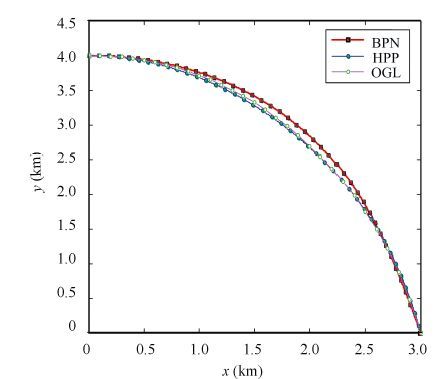 Figure 2 Flight trajectory histories
 Figure 3
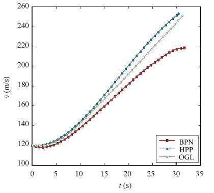 Figure 3 Velocity histories
 Figure 4
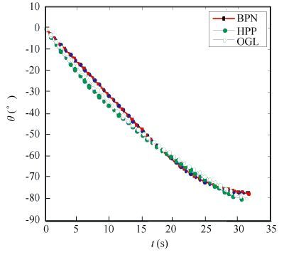 Figure 4 Flight path angle histories
 Figure 5
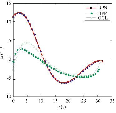 Figure 5 Angle of attack histories
 Figs. 2-5 show the results of variations of states and control variables obtained by the HPP and OGL trajectories. Table 1 gives the terminal trajectory parameters of three guidance laws. It is observed that, despite two completely different approaches, the qualitative behaviors of the states along the HPP and OGL trajectories are remarkably similar as well as the control variable. In other words, the optimum of the proposed optimal guidance law is demonstrated. As shown in Fig. 2, a higher trajectory of BPN than that of OGL. As a result, the missile in BPN employs more control energy than the OGL. Furthermore, the terminal velocity of OGL is greater than that of BPN as shown in Fig. 3 and improved by about 16%. As shown in Fig. 4, the flight path angles rapidly decrease in process and the terminal values of OGL is more access to the expected impact angle in comparison to BPN. Fig. 5 illustrates the attack angle of different guidance schemes and it is observed that curve of OGL and HPP changes evenly. Thus, the proposed OGL has obvious superiority in terminal velocity, flying time, hitting precision and controling impact angle over BPN that presented in Ref. [18] .
According to Eq. (38), it can guarantee to achieve the maximum terminal velocity and satisfies the impact angle and the final position constraints by calculating time-varying proportional coefficient K1 and K2 on the basis of Eq. (37).In conclusion, we can conclude that the proposed optimal guidance law has an appreciable effect in controlling impact angle and maximizing terminal velocity when the missile homing in on the target.
4.2 Simulation Example 2In this numerical simulation, in order to justify the robustness of the proposed optimal guidance law, the simulations are carried out with the proposed optimal guidance law for missile under the condition that there exists aerodynamic uncertainties, and three flight cases with different setting conditions are shown in Table 2. We consider the situations that include maximum and minimum lift-to-drag ratio by validation method of boundary value, where the expected impact angle is set to be -80° and other simulation parameters are the same as the example 1. The results are presented by Figs. 6-13 and Table 3.
表 2
1-10+10
2±0±0
3+10-10
Table 2 Aerodynamic uncertain parameters of three flight cases
表 3
130.970.07-79.99256.89
231.220.08-80.01250.34
331.410.09-80.04245.26
Table 3 Terminal trajectory parameters of three flight cases
Figure 6
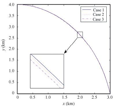 Figure 6 Flight trajectory histories
 Figure 7
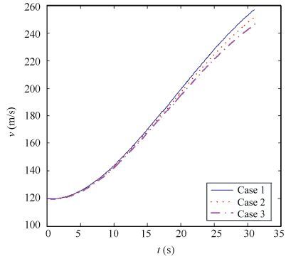 Figure 7 Velocity histories
 Figure 8
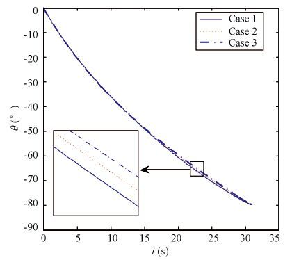 Figure 8 Flight-path angle histories
 Figure 9
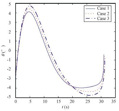 Figure 9 Angle of attack histories
 Figure 10
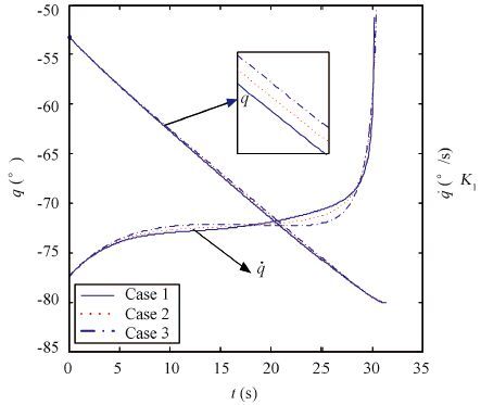 Figure 10 Line-of-sight of angle and rate histories
 Figure 11
 Figure 11 Proportional coefficient histories
 As shown in Fig. 6, the difference of the trajectories is small under three flight cases. Fig. 8 represents the history of the flight path angle, which shows good performance in controlling impact angle for all cases. From Fig. 10, we can obtain that line-of-sight of angle tends to approach the expected impact angle and the line-of-sight of rate converges to zero in three flight cases. It indicates that the proposed optimal guidance law can converge in a finite time. As shown in Fig. 11, the proportional coefficients K1 and K2 change slightly and it is extremely useful to engineering application of practice by taking them as constant to simplify the form of the optimal guidance command. From above analyses, the difference between the result of cases considering the aerodynamics uncertainties and standard cases is small, thus the simulation result demonstrates the proposed optimal guidance law has strong robustness.
5 ConclusionsIn this paper, an analytical formulation of optimal guidance law for missiles with impact angle and miss distance constraint is proposed to achieve the maximal terminal velocity by combining optimal control theory with numerical computation method. The performance of the proposed optimal guidance law is validated by comparable nonlinear simulations with the conventional guidance law. It is interesting to note that the trajectories of the proposed guidance law behave in a similar tendency to optimal solutions. On the other hand, comparing with BPN with impact angle constraint, OGL shows superior performance in maximization of the terminal velocity that improved by about 16% at intercept, satisfaction of impact angle, improvement in miss distance, smaller and smoother angle of attack. Above all, under the conditions with aerodynamic uncertainties, the proposed guidance law has strong robustness. As noted previously, owing to the analytic and simple form of the proposed guidance law, it is suitable for implementation in an airborne digital computer demonstrate to feasibility of on-line optimal control operation.
References
[1] Joseph Z, Ben A, Isaac Y. Advances in Missile Guidance Theory. Virginia: American Institute of Aeronautics and Astronautic, Inc, 1998.25-35. (
 0)
0)[2]Kim M, Grider K. Terminal guidance for impact attitude angle constrained flight trajectories.IEEE Transactions on Aerospace and Electronic System,1973, 9(6): 852-859.(
 0)
0)[3]Zhang Youan, Ma Guoxin, Liu Aili. Guidance law with impact time and impact angle constraints.Chinese Journal of Aeronautics,2013, 26(4): 960-96.(
 0)
0)[4]Lee Y, Kim S H, Lee J I, et al. Analytic solutions of generalized impact-angle-control guidance law for first-order lag system.Journal of Guidance, Control and Dynamics,2013, 36(1): 96-112.(
 0)
0)[5]Lei Dou, Jiao Dou. The design of optimal guidance law with multi-constraints using block pulse functions.Aerospace Science and Technology,2012, 23(1): 201-205.(
 0)
0)[6]Zhao Yao, Sheng Yongzhi, Liu Xiangdong. Sliding mode control based guidance law with impact angle constraint.Chinese Journal of Aeronautics,2014, 27(1): 145-152.(
 0)
0)[7]Ratnoo A, Ghose D. Impact angle constrained guidance against non-stationary non-maneuvering targets.Journal of Guidance, Control and Dynamics,2010, 33(1): 269-275.(
 0)
0)[8]He Shaoming, Lin Defu, Wang Jiang. Continuous second-order sliding mode based impact angle guidance law.Aerospace Science and Technology,2015, 41(1): 199-208.(
 0)
0)[9]Zhao Jiang, Zhou Rui. Unified approach to cooperative guidance laws against stationary and maneuvering targets.Nonlinear Dynamic,2015, 80(1): 1705-1719.(
 0)
0)[10]Yu Wenbin, Chen Wanchun. Guidance law with circular no-fly zone constraint.Nonlinear Dynamic,2014, 78(1): 1953-1971.(
 0)
0)[11] Lee Y, Ryoo C, Kim E. Optimal guidance with constraints on impact angle and terminal acceleration. AIAA 2003-5795, 2003: 1-6. (
 0)
0)[12] Jeong S K, Cho S J, Kim E G. Angle constraint biased PNG. 5th Asian Control Conference. Melbourne, 2004. 1849-1854. (
 0)
0)[13]Harl N, Balakrishnan S N. Impact time and angle guidance with sliding mode control.IEEE Transactions on Control Systems Technology,2012, 20(6): 1436-49.(
 0)
0)[14]Zhang Zhenxing, Li Shihua, Luo Sheng. Terminal guidance laws of missile based on ISMC and NDOB with impact angle constraint.Aerospace Science and Technology,2013, 31(1): 30-41.(
 0)
0)[15] Cherry G. A general, explicit, optimizing guidance law for rocket-propelled spaceflight.AIAA 64-638, 1964.23-27. (
 0)
0)[16]Qian Xingfang, Lin Ruixiong, Zhao Yanan. Flight Dynamics of Missiles.Beijing: Beijing Institute of Technology Press, 2000.(
 0)
0)[17]Wu Cangpou, Xia Yuanqing, Yang Yi. The Optimal Control Theory and Method.Beijing: National Defence Industry Press, 2013.(
 0)
0)[18]Liang Zhuo, Guan Xueyuan, Sun Ruisheng, et al. Calculation of release region for a guided bomb with INS/ GPS based on a compound guidance law.Journal of Ballistics,2007, 19(3): 27-30.(
 0)
0)[19]Darby C L, Hager W W, Rao A V. An hp-adaptive pseudo-spectral method for solving optimal control problems.Optimal Control Applications and Methods,2011, 32(4): 476-502.(
 0)
0)