 ,1,3, Jiang-Xing Chen,1,31Department of Physics,
 2Department of Physics,
First author contact:
Received:2019-08-23Revised:2019-10-18Accepted:2019-10-31Online:2020-01-14
| Fund supported: |

Abstract
Keywords:
PDF (615KB)MetadataMetricsRelated articlesExportEndNote|Ris|BibtexFavorite
Cite this article
Shun Zhan, Ru-Fei Cui, Li-Yan Qiao, Jiang-Xing Chen. Transport of nanodimers through chemical microchip
1. Introduction
Catalytically active micro-objects can display self-propulsion through asymmetry reaction when part of their surface catalyses a chemical reaction in a surrounding environment [1–5]. The controlled motion of synthetic nanomotors has attracted considerable interest in fundamental principles and thus stimulated major research efforts over the past decade in connection to diverse potential applications: targeted drug delivery, motion-based biosensing, nanoscale assembly, environmental remediation, etc [6–11].These small synthetic motors with micro or nano sizes experience very strong thermal fluctuations and operate in regimes where viscous forces dominate [12]. To achieve long-range and directional motion, various external fields have been applied to control their transport. Magnetic fields have been exploited in guiding catalytic nanomotors [13]. However, magnetic control requires the integration of additional magnetic elements in the nanomotors and precise alignment of magnetic moments [14]. Acoustic control has made rapid progress in recent years [15]. For example, it can be utilized in guiding catalytic nanomotors to aggregate and disperse [16], while control of precise motion is still a big challenge. Electric field and light are also applied to control the motion of nanomotors [17, 18].
Without the manipulation by external fields, biological molecular motors, such as kinesins, myosins, and dyneins, use the chemical free energy released by the hydrolysis of adenosine triphosphate ATP as fuel to carry out directed motion along filaments [19]. For synthetic nanomotors, the confined spaces with physical boundary wall, such as capillaries or microchannels and interactions with surfaces, have been applied to assist the directed transport [20–23]. The controlled transport in nanotechnology has been an important topic over the past decade. There are still huge spaces to develop simple but effective lab-on-a-chip devices for transporting micro and nano objects.
In this paper we construct a small chip device consisting of chemical stripe pathways in terms of mesoscopic simulation with hybrid molecular dynamics (MD) and multiple particle collision dynamics (MPC). The chip can transport nanomotors between different containers. The dynamics of dimers passing along the prescribed pathways are studied.
2. Mesoscopic model and simulation method
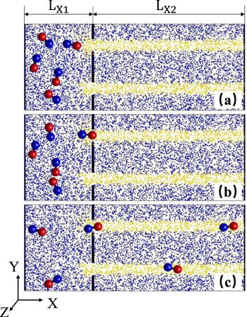
The device is designed by a container and a microchip including chemical pathways, as shown in figure 1. In the container, nanodimers initially diffuse in the liquid solution which is modeled by amounts of point-like solvent particles (S). The container and the chip are bounded by a wall composed of immobile beads with the radius Σb=0.5, except for several entrances. In simulation, the chemical pathways are constructed as follows: when solvent particles (S) diffuse into the stripe pathways they are converted to fuel (F) particles; when molecules diffused out of the pathways they undergo the decay reaction, F (or P)Figure 1.
 New window|Download| PPT slide
Figure 1.Dynamics of the self-propelled nanodimers in the microfluid chip device. Plots show the instantaneous configuration at (a) t=0, (b) t=850, and (c) t=5600 in a 100×40×5 slice. Five dimers with Catalytic spheres (red) and noncatalytic spheres (blue) are initially placed in the left container full of point-like solvent particles (blue). The chemical pathways are indicated by the stripe full of fuel particles (yellow). The black beads bind the container and the chip. The size parameters: ${L}_{x1}=30,{L}_{x2}=70$ .
The dimers are confined in a three-dimensional slab geometry (
The simulation of the entire system is carried out by means of a hybrid molecular dynamics (MD) and multiparticle collision (MPC) scheme [27]. In the MD step with time interval tMD, the motion of each dimer and point-like particles both obey Newton’s equation through calculating total forces on them. No forces among point-like particles in solution are considered. Instead, MPC collision is utilized to simulate the surrounding solution. To carry out collisions, the system is divided into a grid of cells ξ with length a0. Rotation operators
In the simulation, all quantities reported are in dimensionless units based on energy ϵβ, mass ms and distance a0. The temperature of the system is fixed at kBT=1.0. Newton’s equations were integrated using the velocity Verlet algorithm with tMD=0.01. The MPC time is tMPC=1.0 and the rate constant is kcat=0.08. The density of point-like particles in solution is n0=10. The mass of a dimer monomer obeys the relation
3. Results and discussion
Initially, the dimers display random diffusion in the container since there are no fuel particles in the solution, as seen in figure 1(a). In the vicinity of the exits of the container (i.e. the entrances of the chip), the decay of the fuel F (or P)The dimers gradually move into the pathways one by one, as shown in figure 1(c). Since the stripes are full of fuel, the motors can execute self-propulsion along the pathways: the phoretic propulsion drives the dimer with the head of C sphere, which results from the asymmetric distribution of P around the N sphere. Like a micro channel, the chemical route confines the motors within it: once a dimer touches the edge of the stripe pathways, the chemotactic effect will push it back. The confinement from the stripe edge is increased with kcat. Thus, the dimers undergo long navigation along the route, just like the case where the molecular motors move on the filament network. The microchip constructs a bridge to transport nanoparticles among different containers.
It is well known that chemical patterns ranging from stationary regular and labyrinthine patterns to time-evolving structures can arise in chemical systems driven far from equilibrium. For example, the stripe pattern can be achieved from Turing instability in a Chlorite-iodide-malomic acid (CIMA) system [28]. Another example is the patterns formed by the oxidation of CO on the platinum surface [29]. Therefore, the chemical microfluid chip can be realized in experiments. Also, it is expected that similar chips can be constructed by topographical pathways [22] or chemically patterned surfaces [21].
The self-propulsion of dimer nanomotor along the strip is described by the migration velocity of its center of mass along the x axis, denoted by Vcmx. In the simulation, Vcmx can be changed by tuning the potential difference
Figure 2.
 New window|Download| PPT slide
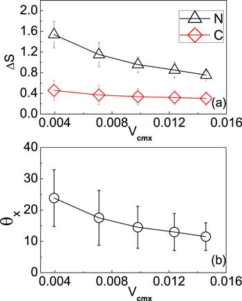
Figure 2.The dependence of the mean square deviation ΔS and the average angle θx on the migration velocity Vcmx. ΔS is defined by
When the width of the path is small, the shortage of the fuel particles leads to slow transport of the dimers. The transport velocity increases with the path width, since more fuel particles will be available. However, when the width of the path is larger than the size of a dimer, increasing the width will gradually induce the decrease of the transport velocity. This is because the dimers are released from the confinement of strips, which results in increased fluctuation when they transport within the path.
The first navigation time TF characterizes the transport dynamics of dimers in the microchip. The value of TF is calculated by recording the time difference between the initial time and the moment when the first dimer touches the right boundary (x=Lx). Due to the chemotactic effect in the entrance of the chip, the nanodimers can rapidly enter into the path and pass through it with small TF. Since the motion of the dimers is quasi-two-dimension, we use the area fraction (
Figure 3.
 New window|Download| PPT slide
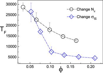
Figure 3.The dependence of the first navigation time TF on the area fraction φ. The circles are obtained by increasing the number of the dimer monomer (Σα=1.0 is fixed, Nd is increased from 5 to 25), while the diamonds are plotted by changing the radius of the dimers (Nd=8). The data is plotted from 20 realizations.
Then, we change the value of φ by fixing the number of the dimers while changing their radius. The size of the dimer increases with φ. Again, the values of TF decrease as φ is increased. Comparing the two cases in figure 3, one can find that the values of TF are smaller in the latter case. This is because a bigger dimer has stronger self-propulsion [30], which makes it easier to sense the F particles in the vicinity of the exits and, therefore, move faster within the fuel path.
To study the influences of Σα and φ on the TF further, we fix φ while changing Nd and Σα. In figure 4 where φ=0.13 is kept, it is found that TF increases with Σα even when Nd is decreased. This means it is the strong self-propulsion that plays the major role on the TF. Therefore, one can conclude that Σα and φ affect TF in different ways: increase of φ enhances the probability of entering the pathways entrance while increase of Σα enhance the velocity of navigation in the chemical pathways.
Figure 4.
 New window|Download| PPT slide
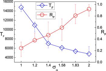
Figure 4.The first navigation time TF (diamonds) and the transported percentage of dimers RP (circles) influenced by the radius (Σα) and the number (Nd) of the dimers. RP is obtained by calculating the percent of the dimers that have reached the x=Lx wall at t=50000. The area fraction φ is kept to be 0.13. Σα is increased from 1.0 to 2.0 and Nd is decreased from 20 to 5. The data is plotted from 20 realizations.
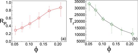
The transport efficiency of the microchip can be described by the transported percentage of dimers RP. After long time evolution, we count the percentage of dimers that have reached the right wall as the value of RP. It is found that RP increases with φ in figure 5(a). One can see that most of the dimers have reached the wall at t=50000 (RP=0.88). When φ is fixed while Σα is increased in figure 4 (circles), it is shown that the RP still increases. Simulation indicates the phenomenon is attributed to the stronger self-propulsion of bigger dimers that move rapidly.
Figure 5.
 New window|Download| PPT slide
Figure 5.(a) RP versus φ. Nd=8 is fixed while the Σα is changed. (b) The averaged reach time Tr versus φ. Tr is calculated through recoding the reach time of every dimer and averaging them. The data is plotted from 20 realizations.
The dependence of the averaged reach time Tr confirms that the transport efficiency is determined by the power of the self-propulsion. In figure 5(b), one can find Tr is decreased with φ. This means the dimers can reach the right wall within a shorter time. Note that an obvious way to increase the transport efficiency is to increase the number of pathways so that the dimers have more available entrances to the chip, which makes it spend less time to enter into the paths. This point has been observed in simulation.
4. Conclusion
In conclusion, we have chiefly put forward a new design of a microfluid chip for transporting small particles. A particle-based model is set to simulate the dynamics. The first navigating time and transport efficiency are studied by changing the size and the volume fraction of the dimers. The increase of φ and Σα both lead to the decrease of TF while their underlying mechanisms are different. The transport efficiency is also increased with the size of the dimer.Nanomotors and micromotors need to be able to navigate microfluidic channels to realize their full potential. The transport of nanoscale objects within microfliudic channels represents a significant step toward designing integrated microdevices. The stripe pattern presented here can be realized in chemical reaction, which provides a micro channel without traditional physical boundary. Further studies on experiments can construct more complex pathway networks to perform special tasks. We hope this study may contribute to develop new design of microfluid device.
Reference By original order
By published year
By cited within times
By Impact factor
DOI:10.1021/ja047697z [Cited within: 1]
DOI:10.1021/acs.accounts.5b00025
DOI:10.1103/PhysRevLett.94.220801
DOI:10.1016/j.ijheatmasstransfer.2018.09.050
DOI:10.1039/C4SM00621F [Cited within: 1]
DOI:10.1038/ncomms1035 [Cited within: 1]
DOI:10.1021/jacs.5b02700
DOI:10.1021/nn301175b
DOI:10.1039/C7CS00516D
DOI:10.1039/C6TA04010A
DOI:10.1002/anie.201806759 [Cited within: 1]
DOI:10.1021/nl500068n [Cited within: 1]
DOI:10.1021/nl900186w [Cited within: 1]
DOI:10.1021/nn300413p [Cited within: 1]
DOI:10.1021/acs.accounts.8b00248 [Cited within: 1]
DOI:10.1002/smll.201403621 [Cited within: 1]
DOI:10.1002/anie.201102096 [Cited within: 1]
DOI:10.1002/smll.201570255 [Cited within: 1]
DOI:10.1038/nature03528 [Cited within: 1]
DOI:10.1002/anie.201301460 [Cited within: 1]
DOI:10.1103/PhysRevLett.117.048002 [Cited within: 1]
DOI:10.1038/ncomms10598 [Cited within: 1]
DOI:10.1039/C7SM00123A [Cited within: 1]
DOI:10.1002/advs.201800028 [Cited within: 1]
DOI:10.1021/acs.accounts.8b00239 [Cited within: 1]
DOI:10.1103/PhysRevLett.98.150603 [Cited within: 1]
DOI:10.1002/9780470371572.ch2 [Cited within: 1]
[Cited within: 1]
DOI:10.1063/1.464323 [Cited within: 1]
DOI:10.1063/1.2908078 [Cited within: 1]
