HTML
--> --> -->Since stratiform clouds are generally horizontally uniform due to relatively gentle updrafts, in-situ aircraft measurements within these clouds have facilitated our better understanding of cloud microphysics. Korolev et al. (2000) studied ice particle habits in stratiform clouds and found that the majority of ice particles in natural clouds were irregularly shaped. However, Stoelinga et al. (2007) showed that the vast majority of snow crystals observed at the ground were a regular identifiable type based on detailed microscope analyses. Bailey and Hallett (2009) derived a comprehensive habit diagram for atmospheric ice crystals, which differed from traditional habit diagrams. Their work suggests the complexity of ice particle habits in natural clouds, since ice crystals undergo processes such as aggregation, riming and breakup during the process of falling through the cloud (Kajikawa and Heymsfield, 1989; Woods et al., 2008; Heymsfield et al., 2015; Erfani and Mitchell, 2017).
Stratiform clouds contribute significantly to spring and fall precipitation over northern China. These clouds are mostly multilayered mixed-phase clouds with various ice crystal number concentrations and habits. These clouds are complicated because generation conditions are different. Aircraft observations have revealed the characteristics of high ice particle concentrations on the order of 102 L in the temperature range of ?2°C to ?6°C due to ice multiplication (Hou et al., 2010; Zhao and Lei, 2014; Yang et al., 2017) and broadened particle size distributions from ?12°C to ?8°C due to riming and aggregation (Zhu et al., 2015). The limited microphysical data indicate that there are dominant ice particle growth mechanisms at some temperature levels, which provides information for the modeling of cloud and precipitation processes (Ma et al., 2007; Guo and Zheng, 2009).
Aircraft measurements have been applied to parameterizations of particle size distributions, cross-sectional area and ice particle habits, which aid in improving the understanding of the mechanisms responsible for stratiform precipitation development (e.g., Heymsfield et al., 2002; Field et al., 2005; Woods et al., 2007). Numerical modeling of stratiform properties and precipitation suggests that the two-moment bulk cloud microphysics scheme is generally better than the one-moment scheme (e.g., Morrison et al., 2009; Luo et al., 2010; Molthan and Colle, 2012). However, the conversion of rimed snow to graupel in association with bulk microphysics may produce large uncertainties. To resolve this problem, Morrison and Grabowski (2008) developed a novel approach that includes only a single ice-phase category but provides more predictive information of the particle properties for representing ice microphysics in models. This approach was advanced by Morrison et al. (Morrison and Milbrandt, 2015; Milbrandt and Morrison, 2016) through proposal of the Predicted Particle Properties (P3) scheme, which includes multiple free ice-categories with the possibility of using a single ice-phase category with four prognostic mixing ratio variables. The P3 scheme avoids the need to partition ice into predefined categories and is a significant improvement from the traditional bulk microphysical schemes. Comparisons of P3 with other microphysical schemes (Morrison et al., 2015; Naeger et al., 2017) suggest that the scheme produced reasonable results for squall line, orographic and warm front precipitation cases.
In this study, we investigate the ability of two microphysical schemes in the Weather Research and Forecasting (WRF) model to simulate a stratiform rainfall event on 20–21 April 2010. The two schemes are the single-category configuration of the P3 scheme (Morrison et al., 2015; hereafter referred to as P3) and the Morrison double-moment scheme (Morrison et al., 2009; hereafter referred to as Morrison). The P3 scheme was selected because it includes a prediction of the rime mass fraction. Although the single-moment Stony Brook University scheme is helpful for investigating the riming degree of snow particles (Lin and Colle, 2011), the scheme is overly simplified compared with the P3 scheme (Morrison and Milbrandt, 2015; Milbrandt and Morrison, 2016). The P3 scheme includes a single ice-phase category with four prognostic mixing ratio variables. The total ice mass, ice number, ice mass from rime growth and bulk rimed volume are predicted. To ensure a smooth transition between the small unrimed ice and larger rimed crystals, the ice particle mass–dimension and projected area–dimension relationships are allowed to vary as functions of particle size and rimed mass fraction. The Morrison scheme was selected because it has been widely evaluated for different precipitation events (e.g., Morrison et al., 2015; Molthan et al., 2016).
The purpose of this study is to examine how well the two schemes simulate microphysics and precipitation in the stratiform cloud case. The contribution of various microphysical processes to cloud particle growth will be compared. Since riming is important in modulating ice particle fallout and surface precipitation distribution, we examine the underlying factors responsible for the precipitation differences by analyzing hydrometeor mass contents, ice particle riming degree and fall speeds. A comparison of the microphysical variables is of considerable importance for improving riming process simulations. The performance of the two schemes is evaluated by comparing the model precipitation distribution to rain gauge observations. Aircraft measurements of liquid water contents (LWCs) and ice particle images are provided to demonstrate in-situ evidence for riming processes.
This paper is organized as follows. In section 2, the case descriptions are presented. Details on the model description and setup are provided in section 3. In section 4, the in-situ aircraft measurements are described. In section 5, the model results are discussed and a comparison of these results with the measured data is presented. Finally, the summary and conclusions are given in section 6.
Observations for this study were obtained from airborne cloud microphysical probes, the C-band Doppler radar at Taiyuan (TY), and surface rain gauge measurements. Two Y-12E aircraft (hereafter Shanxi and Beijing aircraft) equipped with cloud microphysical probes manufactured by DMT (Droplet Measurement Technology) were used to conduct the aircraft observations. LWC estimated from a cloud and aerosol spectrometer on the Beijing aircraft and a cloud droplet probe on the Shanxi aircraft, and particle images observed from cloud imaging probes (CIPs) on both aircraft, will be presented in this study. Detailed descriptions of the instrumentation used in the aircraft measurements were given by Hou et al. (2014).
The mixed-phase cloud system from 20–21 April 2010 was associated with an upper-level trough and surface low-pressure center that moved from southwestern to eastern China. The effects of the system included strong winds, falling temperatures and large-scale precipitation that occurred over central and eastern China. The 24-h accumulated precipitation in a localized region reached 50 mm. Light-to-moderate rain was observed over our study region, which was located in the central part of Shanxi Province, and the 24-h accumulated precipitation was approximately 20 mm. The clouds were well-defined stratiform clouds with predominantly altostratus and stratocumulus clouds. Radar observations (longitude: 112.6°; latitude: 37.7°; 817.0 m MSL) suggested a typical bright band 2.4 km above sea level with a maximum reflectivity of approximately 30 dBZ (see Hou et al., 2014, Fig. 1). The low rain rates, widespread precipitation and typical radar bright band suggested that the rainfall process was stratiform precipitation.
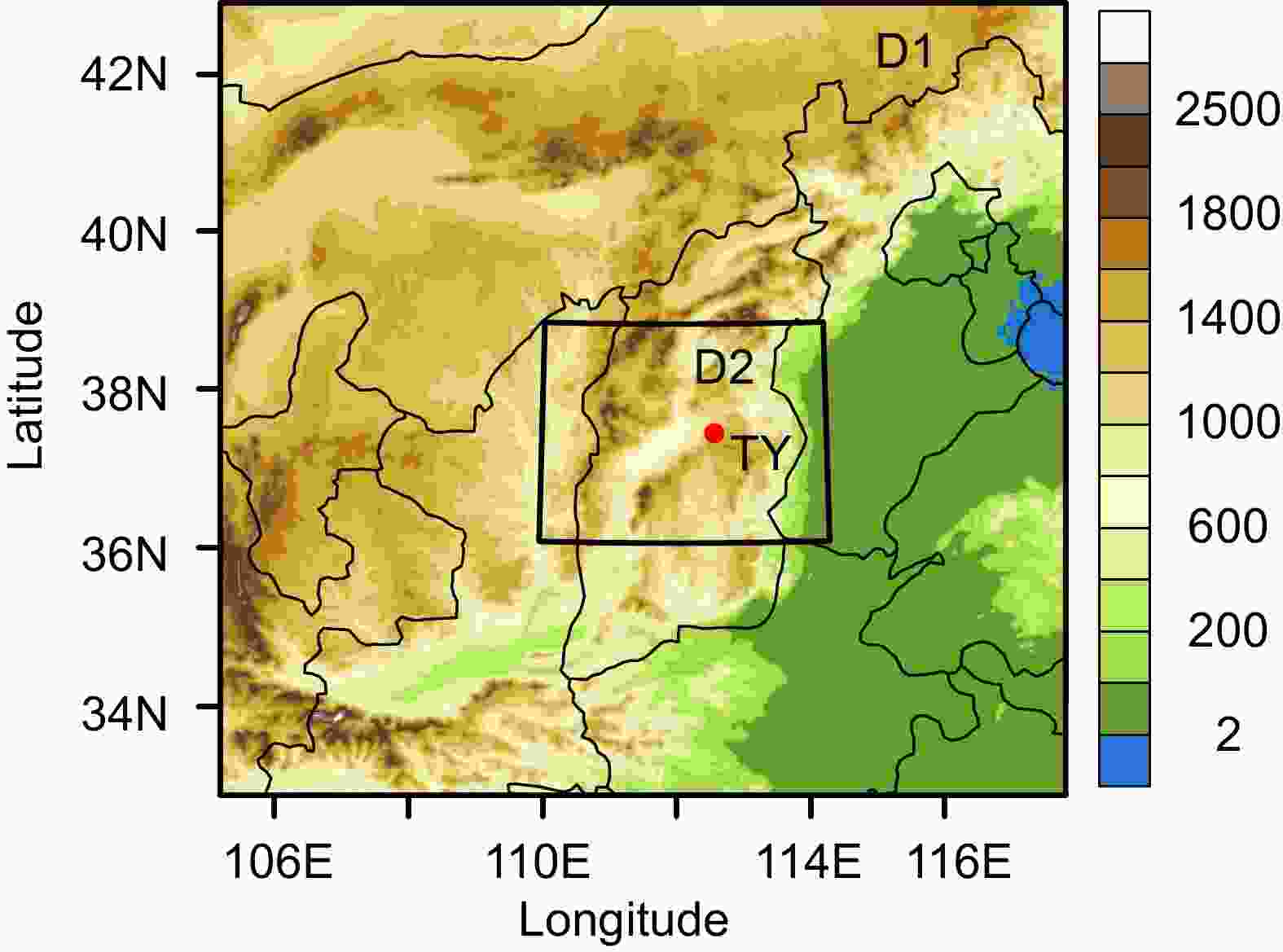 Figure1. Model domain coverage for the 20 April 2010 case. D1 and D2 represent the outer and inner domains, respectively. The location of the radar site at Taiyuan (TY) is indicated by a red dot.
3.1. Model configuration
In this study, we employed the Advanced Research version (V3.9.1) of the WRF model and two model domains (Fig. 1) with two-way nesting and grid spacings of 3 and 1 km. Both domains consisted of 51 vertical levels, with the model top at 50 hPa. The outer domain covered part of northern China and the inner domain covered the rainfall region. The number of grid points was 360 × 360 and 385 × 301 for the outer and inner domains, respectively. The inner domain covered the central part of Shanxi Province, and included the TY radar site, as marked in the figure. The 1° × 1° resolution National Centers for Environmental Prediction reanalysis data were used for the initial and boundary conditions. Both domains were integrated for 24 h from 0000 UTC 20 April to 0000 UTC 21 April 2010.We used the RRTM (Rapid Radiative Transfer Model) for longwave radiation (Mlawer et al., 1997), the Dudhia shortwave radiation scheme (Dudhia, 1989), the YSU (Yonsei University) planetary boundary layer scheme (Hong et al., 2006), and the Noah land surface model (Chen and Dudhia, 2001), in both domains. We did not use cumulus parameterization in the model runs. The two microphysics schemes, including the single-category configuration of the P3 scheme and the Morrison double-moment scheme, were compared for the stratiform cloud case. The representation of rimed ice in the two schemes is briefly described in the following section.
2
3.2. Description of riming
In the current Morrison scheme riming occurs on the cloud ice and snow. Heavily rimed ice is represented by a single category (graupel/hail). Following Rutledge and Hobbs (1984), the minimum mixing ratios of 0.1 and 0.5 g kg?1 for the snow and cloud water are required to produce graupel through the riming of snow. The portion of rime on the snow that is converted to graupel is given by Reisner et al. (1998). Graupel also forms through the freezing of rain. Snow and graupel grow through deposition, riming, accretion of rain and collection of cloud ice. Cloud ice, snow, graupel and hail are assumed to be spherical with bulk densities of 500, 100, 400 and 900 kg m?3, respectively. Ice particle terminal fall speeds are given as a power law of the diameter without explicit dependence on their densities.In the single-category configuration of the P3 scheme, the ice microphysical processes and parameters are calculated in terms of the particle mass–dimension and projected area–dimension relationships. The mass–dimension relationship varies temporally and spatially as small spherical ice, larger unrimed ice, partially rimed crystals and graupel are considered. Thus, the ice particle size distribution is partitioned into different regions, and the bulk density and diameter vary depending on the history of rime growth (Morrison and Milbrandt, 2015). Different from the terminal fall speed formulation in Morrison, the ice fall speed in P3 follows a power law relationship based on the particle Reynolds number and Davis number depending on the rime mass fraction. Various microphysical processes including nucleation, deposition, sublimation, riming and self-collection are calculated in the model.
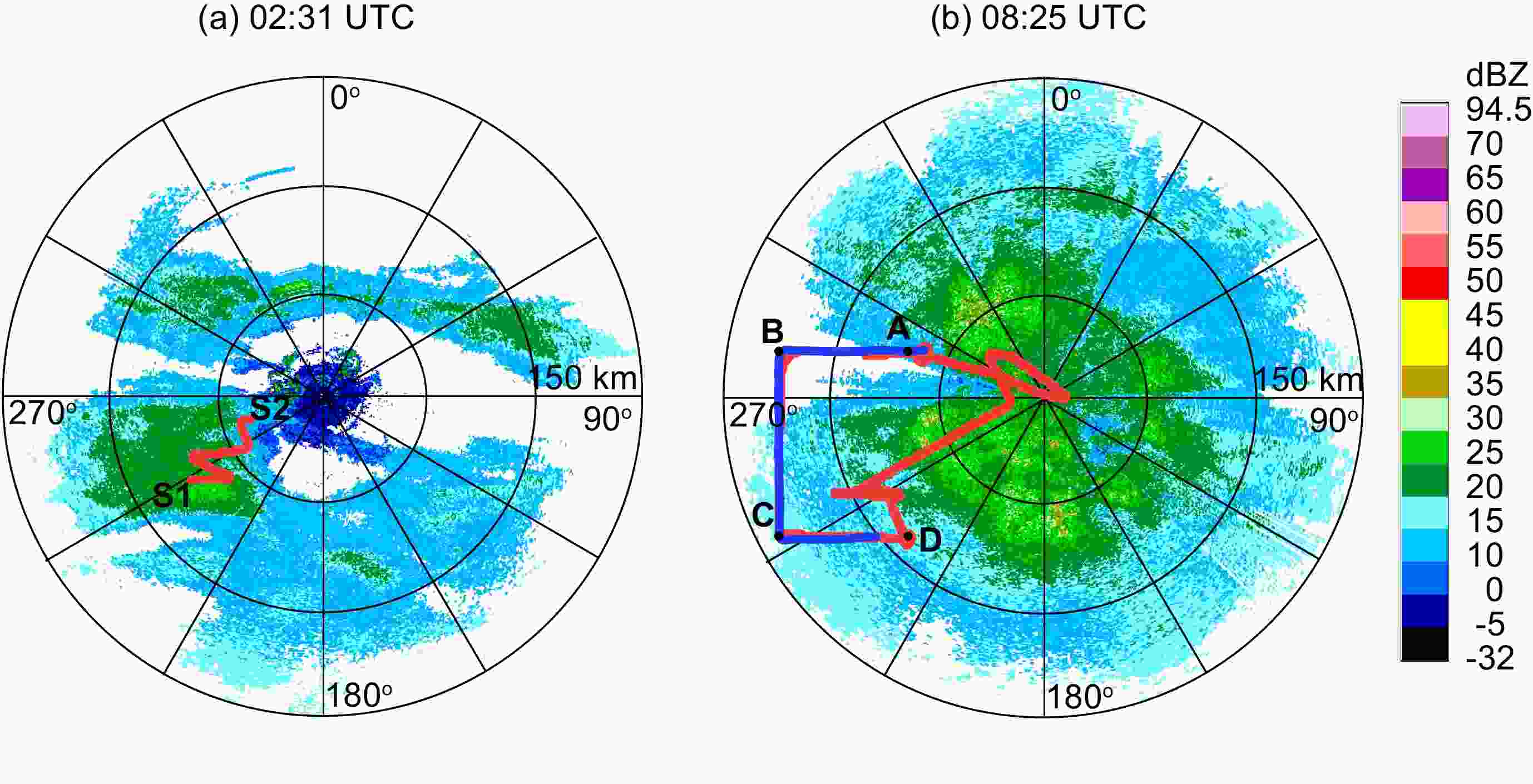 Figure2. PPI radar display of the radar reflectivity factor (units: dBZ) from the Taiyuan radar at (a) 0231 UTC and (b) 0825 UTC 20 April 2010 with an elevation of 1.5°. The range markers are 50 km. Part of the flight track is also shown in the figure. The red line from S1 to S2 represents the horizontal flight leg at 3.6 km observed by the Shanxi aircraft during 0230–0250 UTC 20 April 2010. The red and blue lines from A, B, C to D represent horizontal flight legs at 3.7 and 4.3 km, observed respectively by the Shanxi and Beijing aircraft during 0825–0910 UTC 20 April 2010.
To provide information on crystal types and growth conditions, the LWC and representative images from the CIP along the flight track are shown in the following figures. The data were averaged over 10 s to reduce spurious variability.
Figure 3 shows the time series of LWC and sample images from CIP at 3.6 km (?4.2°C to ?0.4°C) during 0230 and 0250 UTC. There was considerable variability in the LWCs; the maximum value was 0.23 g m?3 at 0231 UTC, while extremely low values of less than 0.01 g m?3 occurred at other times. Dendrites and aggregates of dendrites were common in this region, with some being even larger than the maximum range of the CIP (25–1550 μm). Needles and irregulars were also observed. Particle sizes generally decreased from 0230 to 0250 UTC with a decrease in LWCs.
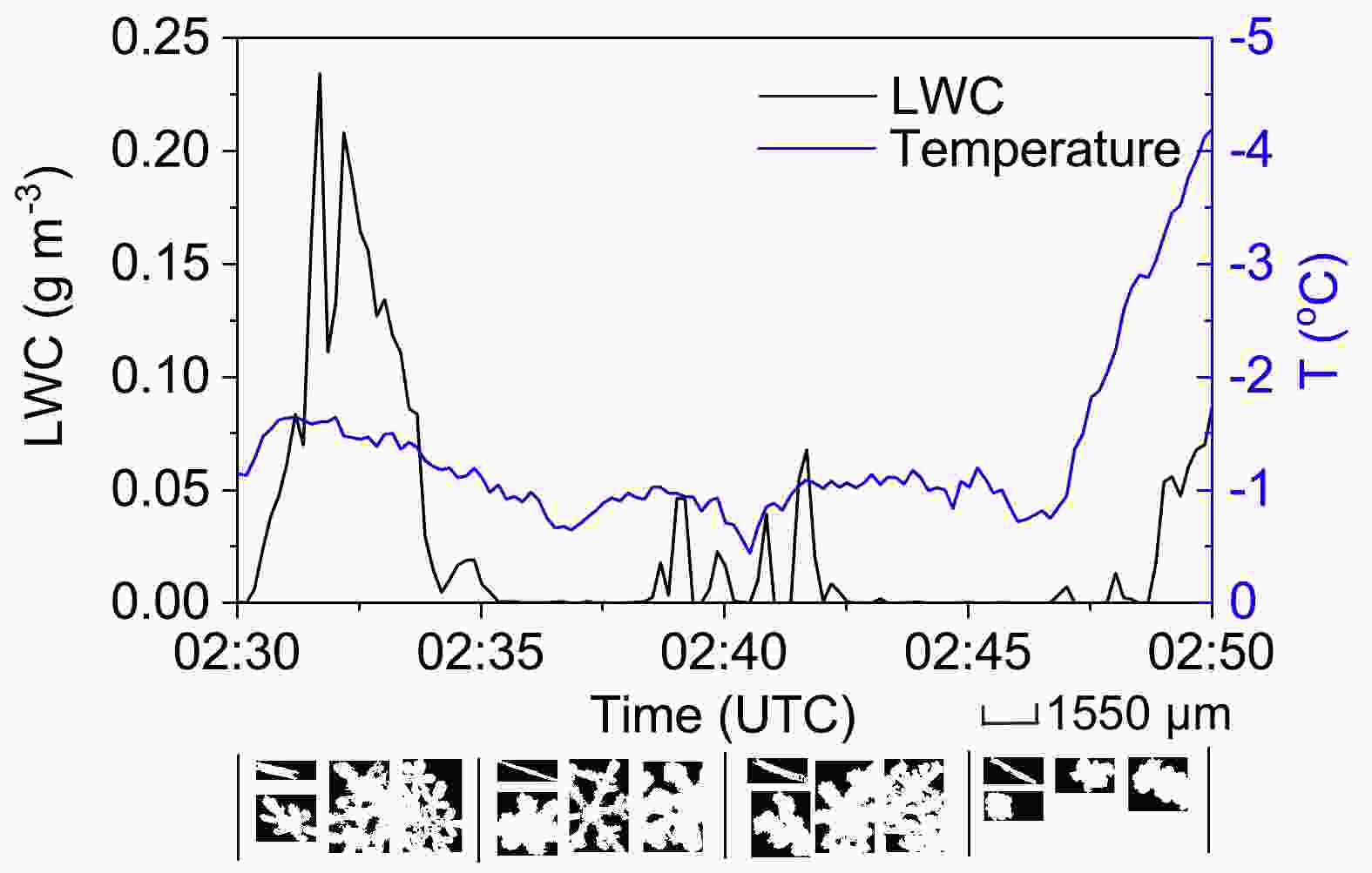 Figure3. Time series of LWC (black) and temperature (blue) at 3.6 km during 0230–0250 UTC 20 April 2010. Sample images from CIP over every 5 min are also shown.
For the mature stage, LWCs at 4.3 km (Fig. 4a) with temperatures of ?4.3°C to ?2.6°C were generally between 0.02 and 0.06 g m?3, with a maximum value of 0.098 g m?3. Plates, assemblages of plates, columns with capped plates and plates with sector-like extensions were common at this height level. Many crystals were moderately rimed plates or dendrites. Needles and combinations of needles also existed but were not dominant. LWCs at 3.7 km (Fig. 4b) varied significantly from less than 0.01 g m?3 to 0.14 g m?3 at temperatures between ?1.7°C and ?0.5°C. Needles in a more pristine state were predominant in this region, suggesting that vapor deposition was the dominant growth mechanism. The cloud conditions were favorable for ice diffusional growth by cloud vapor depletion. In addition, large numbers of needle combinations, capped columns and assemblages of capped columns were observed during 0830 and 0850 UTC. During the following time from 0850 to 0910 UTC, ice particles changed to rimed dendrites and rimed capped columns. This observation indicated ice growth from cloud liquid water depletion.
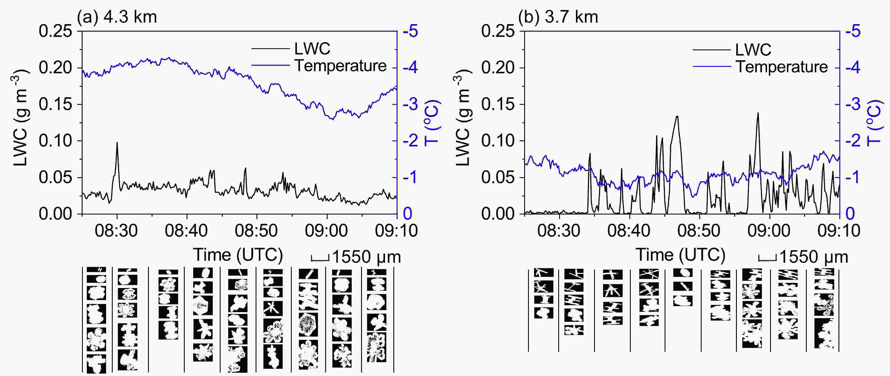 Figure4. Time series of LWC (black) and temperature (blue) at (a) 4.3 km and (b) 3.7 km during 0825–0910 UTC 20 April 2010. Sample images from CIP every 5 min are also shown.
CIP images suggested a mixture of particle habits varying from needle and dendrites to plates at temperatures between ?5°C and 0°C due to the differences in supersaturation and LWCs. The occurrence of moderately rimed dendrites and plates indicated that riming contributed significantly to ice particle growth at the mature stage of precipitation. In addition, aggregation played an important role in producing large particles at both the early and mature precipitation stages. In other words, aggregation coexisted with deposition or riming, producing many large particles in the form of dendrite and capped column aggregations.
5.1. Precipitation distribution
To evaluate the performance of the two microphysical schemes, the simulated precipitation distribution was compared with that from the rain gauge observations. Figure 5 presents the spatial distribution of the 24-h accumulated precipitation from observations and the model simulations in both domains. The precipitation observations from the rain gauges are represented by colored dots. According to the rain gauge observations (Fig. 5a), light to moderate rainfall with values between 5 and 30 mm occurred over Shanxi Province. Higher amounts of rainfall occurred in the western and southern parts, with a peak rainfall amount of 88.2 mm located in the southern part of the outer model domain. Compared with the observations, the precipitation pattern from the P3 experiment (Fig. 5b) also showed scattered precipitation regions in Shanxi and a heavier rainfall band in the southern part. However, the peak rainfall amount was underpredicted as the simulated value was no greater than 75 mm and the rainfall band was displaced westward. In comparison with P3, Morrison (Fig. 5c) produced a generally similar precipitation pattern, but smaller regions for values larger than 25 mm along the 36°N cross section.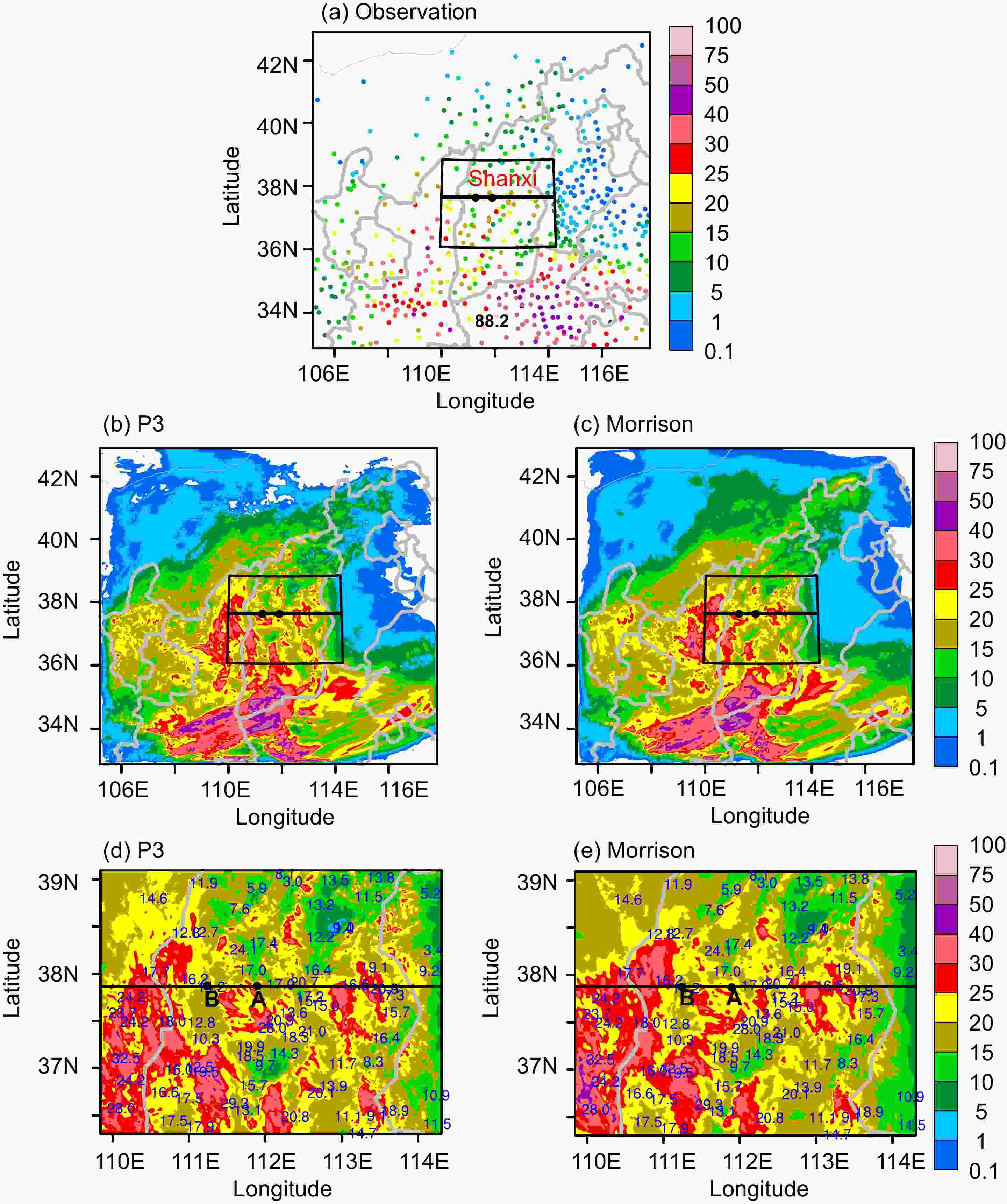 Figure5. Spatial distribution of 24-h accumulated precipitation (units: mm) from (a) observations, (b) P3 and (c) Morrison in the 3-km domain, and (d) P3 and (e) Morrison in the 1-km domain. Observation data from rain gauge sites in (a) are marked by colored dots. The black box in (a–c) shows the location of the 1-km domain. The two black points A and B are the same as in Fig. 2b. The black line crossing A and B shows the location of the cross section that will be used in the following figures. Blue marked values in (d, e) are rain gauge observations.
To more clearly show the simulated precipitation, we also provide precipitation distributions from the inner domains of both schemes (Figs. 5d and e). For our region of interest, the observed 24-h rainfall (marked in Fig. 5d) was generally between 10 and 30 mm. The model tended to overestimate the precipitation since larger areas with precipitation amounts of over 25 mm were produced by both P3 and Morrison. However, we can see differences in the precipitation distribution from a detailed comparison of the two schemes. For the area west of 111°E, Morrison (Fig. 5e) produced stronger precipitation with larger areas over 25 mm than P3 (Fig. 5d). In contrast, for the area east of 112°E, such as the lower right part of the model domain, weaker precipitation was found in Morrison. The domain-averaged (1-km domain) precipitation amounts from P3 and Morrison were quite similar at 20.35 and 20.32 mm, respectively. As the cloud development was from west to east, the higher rainfall amount in the western part and lower rainfall amount in the eastern part from Morrison indicated faster precipitation in Morrison than that in P3.
The differences in the precipitation distribution between the two schemes is further revealed in Fig. 6. The figure shows the 24-h accumulated precipitation along the cross section 37.89°N (the black line in Figs. 5d and e) from the two runs and rain gauge observations. The WRF model with either microphysical scheme captured the variation in precipitation from the western to eastern model domains. However, a higher degree of overprediction around the regions of 110°–111°E and 112°–113°E and a lower degree of overprediction around the regions east of 113°E were found in Morrison. In other words, the overall precipitation distribution from P3 had a systematic eastward shift in P3 and not in Morrison. Overall, compared to the results from Morrison, the P3 results showed an eastward shifted precipitation pattern, leading to an improved spatial distribution.
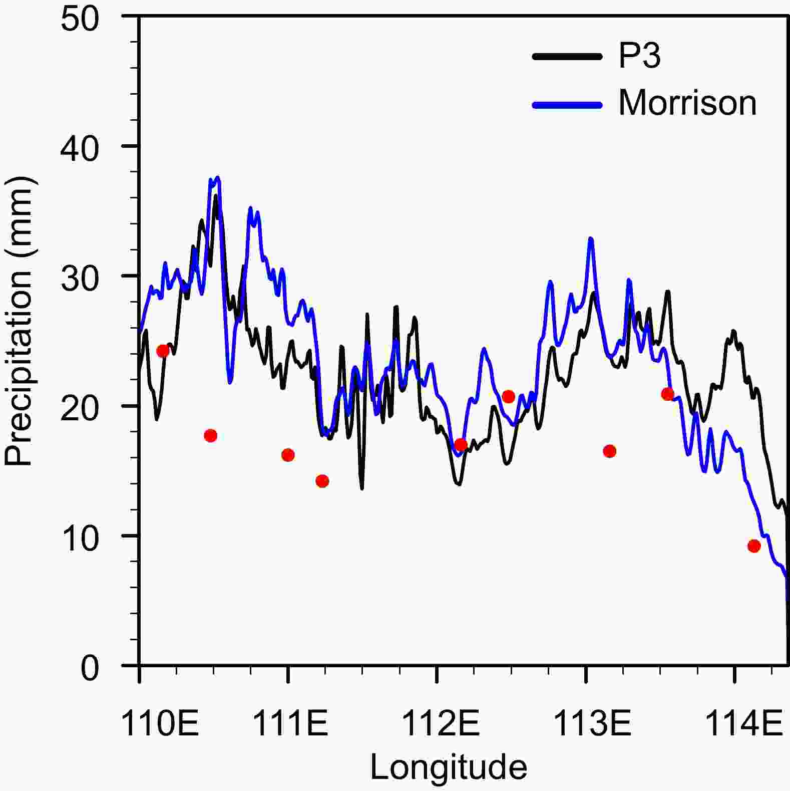 Figure6. The 24-h accumulated precipitation from 0000 UTC 20 April to 0000 UTC 21 April 2010 along 37.89°N for P3 and Morrison simulations. The cross section location is shown by the black line in Figs. 5d and e. The red points represent station observations in the vicinity of the cross section.
To analyze the temporal evolution of the rainfall event, 6-h accumulated precipitation valid at 0600 and 1200 UTC 20 April from both schemes and observations are presented in Fig. 7. The observed rainfall between 0000 and 0600 UTC was rather small, with peak values of 4 mm in the western part, indicating the initiation stage of precipitation. Light rainfall was found in both schemes, even though some degree of overprediction was shown west of 111°E. One difference between the two schemes was that the precipitation extended more eastward in Morrison than in P3, suggesting that the stratiform cloud moved relatively faster in Morrison. Six hours later, more rain was observed, and the peak rainfall was 16 mm in the center of the domain. Larger differences in the precipitation distributions between P3 and Morrison (Figs. 7b and d) were observed, including more rainfall in the western part at 110°E and less rainfall at 112°E in Morrison than in P3. Considering that the observed peak rainfall suggested an increased trend with values from 13 to 16 mm from 110°E to 112°E, the eastward adjustment of precipitation in P3 agreed better with the observations.
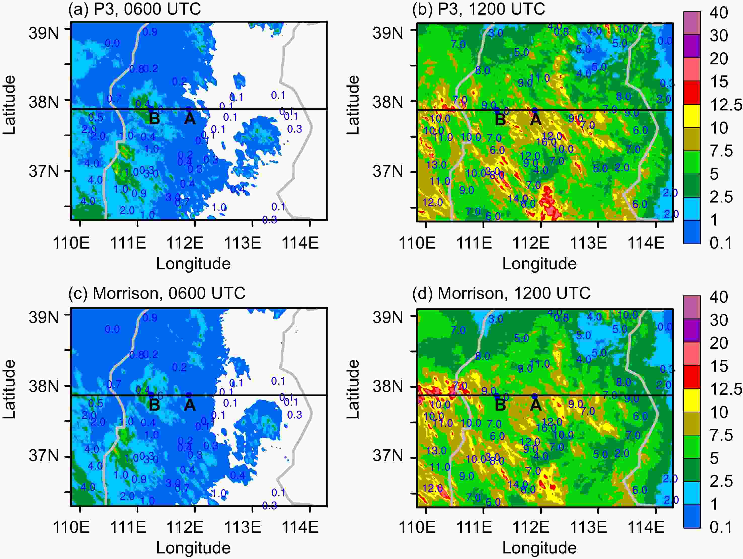 Figure7. Spatial distribution of 6-h accumulated precipitation (units: mm) from observations and simulations: (a) P3 at 0600 UTC; (b) P3 at 1200 UTC; (c) Morrison at 0600 UTC; and (d) Morrison at 1200 UTC 20 April. The black line crossing A and B is the same as in Figs. 5d and e. Blue marked values are rain gauge observations.
Overall, although the domain-averaged precipitation from the two schemes were quite close to each other, the temporal and spatial evolutions of the precipitation patterns revealed that P3 agreed better with the observations. An analysis of the surface precipitation temporal evolution indicated a faster fallout of precipitation particles in Morrison. P3 showed slower rainfall by shifting the precipitation pattern eastward toward what was observed.
2
5.2. Microphysical structure
Ice particle riming intensities and fall speeds play an important role in influencing the precipitation distribution, and thus we compared the microphysical variables from the two schemes in this section. Figure 8 shows the domain-averaged vertical profiles of the cloud species and major processes for ice growth from the two microphysical schemes at 0900 UTC. Deposition in Morrison refers to both ice and snow deposition, as well as riming. The cloud water in P3 (Fig. 8a) was located between the cloud base and 4.5 km, with a maximum of 0.06 g m?3 at 2.7 km, while the cloud water content in Morrison (Fig. 8c) was larger, with a maximum of 0.09 g m?3 and a vertical extent of up to 6.7 km. Differences in cloud water contents may be attributable to the complex interactions between various microphysical processes. However, it should be noted that Morrison employs the saturation adjustment approach (Morrison et al., 2005), while P3 explicitly calculates condensation and evaporation based on predicted supersaturation. This may lead to differences in the distribution of cloud water mass among various microphysical schemes. For example, Fan et al. (2017) found that the bulk schemes using the saturation adjustment for calculating droplet diffusional growth produced larger cloud water mass than the bin scheme. Naeger et al. (2017) showed that the saturation adjustment in the Morrison scheme promoted excessive amounts of cloud water evaporative cooling, while the explicit calculation of cloud water in P3 produced limited amounts of evaporational cooling. To evaluate which scheme predicts a better representation of saturation values, a comparison of vapor and cloud water profiles between aircraft observations and model results is needed in the future.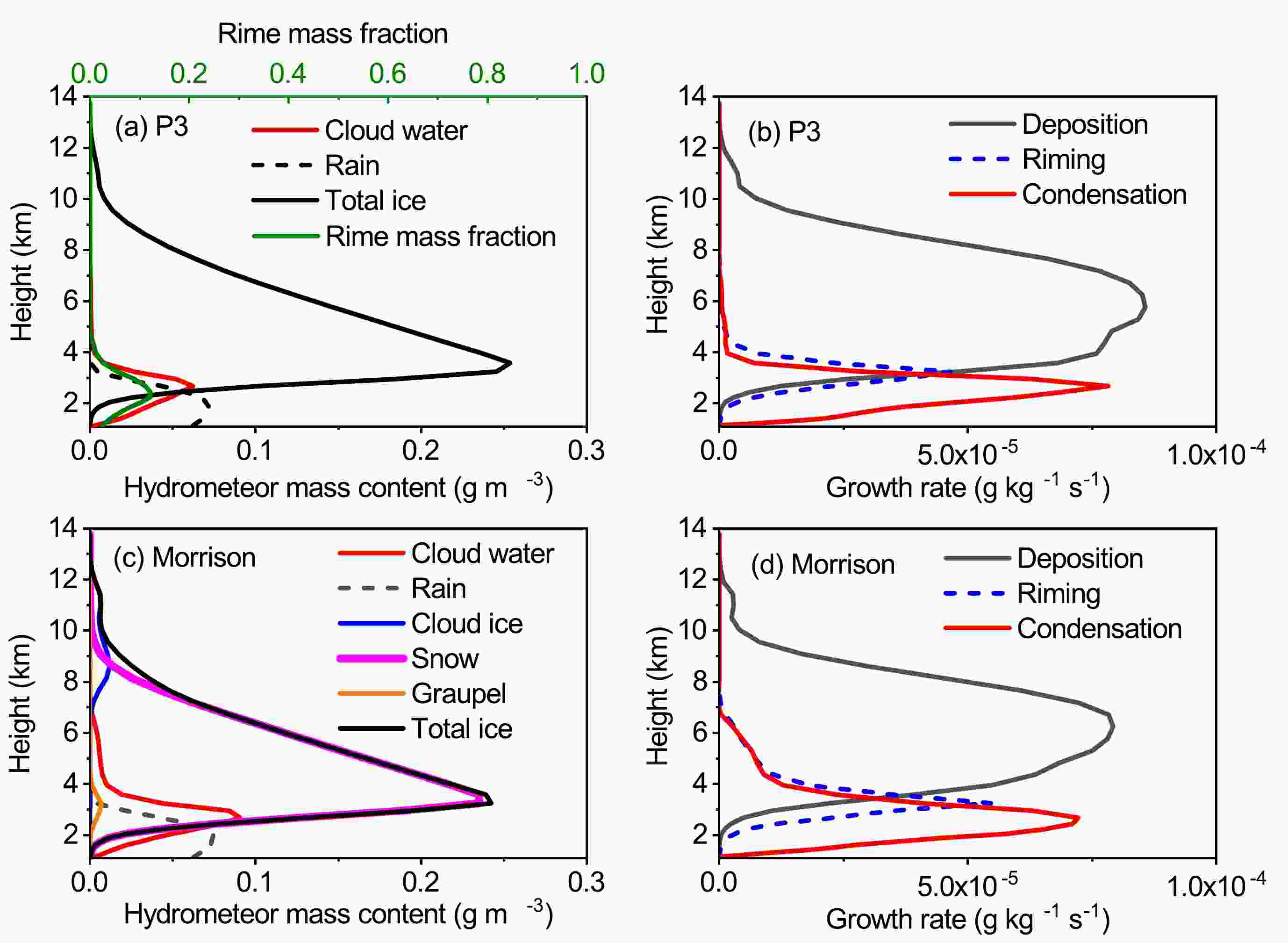 Figure8. Vertical profiles of domain-averaged (a) cloud species and (b) three major processes in P3, and (c) cloud species and (d) three major processes in Morrison, at 0900 UTC 20 April. The rime mass fraction from P3 is shown by the green line in (a).
The total ice content in P3 (Fig. 8a) was much higher than the LWC, exceeding 0.25 g m?3 at 3.6 km. This indicated active ice particle growth in the cold layer. The domain-averaged rime mass fraction had a maximum of 0.12 at 2.4 km, suggesting that the stratiform cloud belonged to a light riming case. In Morrison (Fig. 8c), ice particles were separated by predefined categories, so the total ice content predominantly included snow, with a maximum of approximately 0.24 g m?3, small amounts of cloud ice at higher levels above 7 km, and graupel, with a maximum of less than 0.01 g m?3, at lower levels. The total ice and rain content profiles in P3 were generally similar to Morrison, although there were differences in ice classifications and related processes such as ice initiation and ice multiplication.
The ice depositional growth in P3 (Fig. 8b) was predominantly at heights above 4.0 km, with a maximum of over 8 × 10?5 g kg?1 s?1 at approximately 6 km. Riming in P3 occurred at lower levels, between 2 and 5 km, with maxima of less than 5 × 10?5 g kg?1 s?1. In comparison, ice particle growth in Morrison (Fig. 8d) was also dominated by deposition at higher levels and riming at lower levels. The difference was that riming in Morrison extended higher to approximately 7 km and the riming rate was slightly higher than that in P3, due to the different distributions of cloud water content.
The P3 scheme produced quite similar overall results with that of Morrison in terms of domain-averaged hydrometeor distribution and surface rainfall amounts. However, notable differences in microphysical variables could be seen from more detailed comparison. Figures 9 and 10 show vertical cross sections of hydrometeor mass contents, particle fall speeds and other variables along 37.89°N at 0900 UTC from Morrison and P3. The region between the two black vertical lines is the target area along the flight track from point A to point B.
 Figure9. Vertical cross sections of (a) cloud water (units: g m?3), (b) total ice (units: g m?3), (c) snow (units: g m?3), (d) graupel (units: g m?3), (e) mass-weighted snow fall speed (units: m s?1) and (f) mass-weighted graupel fall speed (units: m s?1), along 37.89°N at 0900 UTC 20 April from Morrison. The two black vertical lines show the target region along the flight track from point A to point B (111.9°–111.2°E).
 Figure10. Vertical cross sections of (a) cloud water (units: g m?3), (b) total ice (units: g m?3), (c) rime mass fraction, (d) mass-weighted mean ice particle density (units: kg m?3), (e) mass-weighted mean ice particle fall speed (units: m s?1) and (f) mass-weighted mean ice particle size (units: mm), along 37.89°N at 0900 UTC 20 April from P3. The two black vertical lines are the same as in Fig. 9.
According to Fig. 9a, Morrison produced extensive cloud water (Fig. 9a), with a cloud water top height of approximately 6.0 km and peak values up to 1.0 g m?3. Since the cloud moved from west to east and combined with a significantly larger cloud water vertical extent in the west, fast ice particle growth resulted in the west area, in correspondence to the total ice peak values of 1.5 g m?3 located west of 111°E (Fig. 9b). The major contributor to the total ice was snow (Fig. 9c), with peak values of approximately 1.2 g m?3. The amount of graupel was very small, with peak values of only 0.5 g m?3, indicating light riming within the cloud. Snow fall speeds (Fig. 9e) in Morrison were generally less than 1.5 m s?1, while graupel fall speeds (Fig. 9f) increased abruptly to 2.0–2.5 m s?1, as constant densities of 100 kg m?3 for snow and 400 kg m?3 for graupel were assumed in the scheme. Although the amounts of graupel were small, their fast fall out contributed significantly to the accumulation of surface rainfall in the western area of the model domain. The larger cloud water amounts and faster falling graupel may explain the larger rainfall simulated in the western area of the domain in Fig. 7d.
P3 produced less cloud water (Fig. 10a) than Morrison in terms of both peak values and vertical extent. Another difference in the cloud water distribution between the two schemes was that the peak values in P3 were located approximately in the middle of the model domain, and not in the west as in Morrison. Therefore, the location of the total ice was also in the middle (Fig. 10b). The maximum ice contents in P3 were much lower than those in Morrison at less than 0.6 g m?3.
The rime mass fraction (Fig. 10c) varied significantly from less than 0.2 to over 0.8, with peak values generally corresponding to cloud water maxima. Mass-weighted ice particle densities (Fig. 10d) were mostly low, with values of less than 100 kg m?3. However, some high values over 600 g m?3 existed due to heavy riming in locations with abundant liquid water. For heights above 4 km, ice particle fall speeds (Fig. 10e) were generally less than 1.5 m s?1, as in Morrison. In contrast, for heights between 2 and 4 km, ice particle fall speeds varied significantly from 1.5 to 10 m s?1, as an increase in riming intensity translated to increases in particle densities and fall speeds. Peak values of ice particle sizes (Fig. 10f) occurred mostly west of the target region, as that part of the cloud developed earlier in the process of east to west movement.
The aircraft observations from point A to point B occurred between 0825 and 0840 UTC, so it was reasonable to compare the measurements with the model results at 0900 UTC. Overall, the simulated ice particles from P3 in the target region between 111.22°E and 111.9°E existed in a large temperature range with an ice water content of 0.2 g m?3 extending vertically up to approximately 6 km, while the LWC was located below 4 km. For the levels above the 0°C layer, the rimed mass fraction was less than 0.5, which indicated light to moderate riming at 0900 UTC. The mass-weight ice particle densities were less than 100 kg m?3. Ice particles in the target region had fall speeds of 1–2 m s?1 and sizes of 1–3 mm. The simulated predominant ice particles with light to moderate riming degrees generally agreed with the observed riming particles from the in-situ aircraft observations, even though the observed riming degree was not quantitatively determined. As discussed in Hou et al. (2014), some heavily rimed plates, graupel-like snow and plates were also observed during the descent and ascent flight legs. According to Locatelli and Hobbs (1974), for heavily rimed particles in the size range of 500–1000 μm, dendrites are assumed to have a fall speed in the range of 2.2 to 2.8 m s?1, while lump type graupel-like snow should have a fall speed in the range of 3.3 to 4.0 m s?1. Therefore, the P3 scheme captured the general cloud structures and riming intensities within the stratiform clouds.
The LWCs and ice particle habits during two precipitation stages of the 20 April case were analyzed. The horizontal observations at selected heights suggested that LWCs varied from the maxima of 0.23 g m?3 at the early precipitation stage to the lower maxima of 0.14 g m?3 at the mature stage. CIP images suggested a mixture of particle habits varying from needle and dendrites to plates at temperatures between ?5°C and 0°C due to differences in supersaturation and LWCs. Dendrites with well-distinguished branches and their assemblages at ?2°C to ?1°C during the early stage suggested that deposition and aggregation were dominant growth modes. In contrast, the observed moderately rimed dendrites and plates indicated that riming contributed significantly to ice particle growth at the mature precipitation stage. Aggregation coexisted with deposition or riming, and played an important role in producing many large particles in the form of dendrite and capped column aggregations.
The simulated accumulated precipitation for the 20 April case from the two microphysical schemes was compared with that from the rain gauge observations. The domain-averaged values of the 24-h accumulated surface precipitation from the two schemes were quite close to each other. Both schemes underestimated the peak rainfall values in the outer domain but overestimated the rainfall amount in the inner domain of our stratiform region of interest. However, differences existed in the temporal and spatial evolutions of precipitation distribution. An analysis of the surface precipitation time evolution indicated faster precipitation in Morrison, while P3 showed slower rainfall by shifting the precipitation pattern eastward toward what was observed. The differences in precipitation between the two schemes were related to the distribution of the cloud water content and fall speeds of rimed particles. Morrison generally produced snow fall speeds of less than 1.5 m s?1 and rimed-category graupel fall speeds to over 2.0 m s?1. In contrast, P3 had ice particle fall speeds varying from 1.5 to 10 m s?1, as the riming intensity translated to increases in particle densities and fall speeds.
Overall, the vapor deposition was the major contributor to ice particle growth. Riming was important in the ice particle growth at lower levels above the 0°C layer. The cloud system belonged to a light riming case. P3 simulated the stratiform precipitation event better as it captured the gradual transition of the mass-weighted fall speeds and densities from unrimed to rimed particles.
Only one case was selected in the study. The predicted rimed mass fraction in the P3 scheme is an important parameter for studying riming growth in clouds. To further evaluate the model performance, more comprehensive observations of ice habits and riming degrees are needed.
Acknowledgements. The reviewers were very helpful in improving the manuscript. We acknowledge their thoughtful suggestions. This work was supported by the National Key Research and Development Program of China (Grant No. 2018YFC1507900) and the National Natural Science Foundation of China (Grant Nos. 41575131, 41530427 and 41875172).
